Page 627 of 2000
2AZ-FE ENGINE MECHANICAL – CYLINDER HEADEM–83
EM
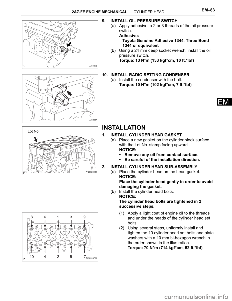
9. INSTALL OIL PRESSURE SWITCH
(a) Apply adhesive to 2 or 3 threads of the oil pressure
switch.
Adhesive:
Toyota Genuine Adhesive 1344, Three Bond
1344 or equivalent
(b) Using a 24 mm deep socket wrench, install the oil
pressure switch.
Torque: 13 N*m (133 kgf*cm, 10 ft.*lbf)
10. INSTALL RADIO SETTING CONDENSER
(a) Install the condenser with the bolt.
Torque: 10 N*m (102 kgf*cm, 7 ft.*lbf)
INSTALLATION
1. INSTALL CYLINDER HEAD GASKET
(a) Place a new gasket on the cylinder block surface
with the Lot No. stamp facing upward.
NOTICE:
• Remove any oil from contact surface.
• Be careful of the installation direction.
2. INSTALL CYLINDER HEAD SUB-ASSEMBLY
(a) Place the cylinder head on the head gasket.
NOTICE:
Place the cylinder head gently in order to avoid
damaging the gasket.
(b) Install the cylinder head bolts.
NOTICE:
The cylinder head bolts are tightened in 2
successive steps.
(1) Apply a light coat of engine oil to the threads
and under the heads of the cylinder head set
bolts.
(2) Using several steps, uniformly install and
tighten the 10 cylinder head set bolts and plate
washers with a 10 mm bi-hexagon wrench in
the order shown in the illustration.
Torque: 70 N*m (714 kgf*cm, 52 ft.*lbf)
A114362
A112227
A126929E01
F050595E03
Page 630 of 2000

EM–862AZ-FE ENGINE MECHANICAL – CYLINDER HEAD
EM
22. INSTALL ENGINE MOUNTING INSULATOR RH (See
page EM-41)
23. INSTALL RADIATOR RESERVOIR (See page EM-112)
24. INSTALL GENERATOR ASSEMBLY (See page CH-15)
25. INSTALL FAN AND GENERATOR V BELT (See page
EM-7)
26. INSTALL FRONT SUSPENSION MEMBER
REINFORCEMENT RH (See page EM-7)
27. CONNECT ENGINE WIRE
(a) Connect the ground cable with the bolt.
Torque: 8.4 N*m (86 kgf*cm, 74 in.*lbf)
(b) Connect the camshaft position sensor connector.
(c) Connect the engine coolant temperature sensor
connector.
(d) Connect the engine oil pressure switch connector.
(e) Connect the radio setting condenser connector.
(f) Connect the heater water inlet hose.
28. CONNECT NO. 1 RADIATOR HOSE
(a) Connect the hose to the cylinder head.
29. INSTALL CAMSHAFT TIMING OIL CONTROL VALVE
ASSEMBLY (See page ES-396)
30. INSTALL EXHAUST MANIFOLD CONVERTER SUB-
ASSEMBLY
(a) Install a new gasket onto the cylinder head.
(b) Temporarily tighten the exhaust manifold converter
with the 5 nuts.
(c) Tighten the 5 nuts in the sequence shown in the
illustration.
Torque: 37 N*m (377 kgf*cm, 27 ft.*lbf)
(d) Connect the air-fuel ratio sensor connector.
A098748E01
A114348
A112190E01
A098744E01
Page 650 of 2000

2AZ-FE ENGINE MECHANICAL – ENGINE UNITEM–123
EM
DISASSEMBLY
1. REMOVE IDLER PULLEY (See page EM-23)
2. REMOVE OIL DIPSTICK
3. REMOVE OIL DIPSTICK GUIDE (See page EM-57)
4. REMOVE MANIFOLD STAY (See page EM-57)
5. REMOVE NO. 2 MANIFOLD STAY (See page EM-58)
6. REMOVE NO. 1 EXHAUST MANIFOLD HEAT
INSULATOR (See page EM-58)
7. REMOVE EXHAUST MANIFOLD CONVERTER SUB-
ASSEMBLY (See page EM-58)
8. REMOVE WATER INLET (See page CO-15)
9. REMOVE THERMOSTAT
10. REMOVE NO. 1 WATER BY-PASS PIPE
(a) Remove the bolt, 2 nuts, pipe and gasket.
11. REMOVE NO. 3 WATER BY-PASS PIPE
(a) Remove the bolt, 2 nuts, pipe and gasket.
12. REMOVE V-RIBBED BELT TENSIONER ASSEMBLY
(See page EM-26)
13. REMOVE CAMSHAFT TIMING OIL CONTROL VALVE
ASSEMBLY (See page ES-395)
14. REMOVE KNOCK SENSOR (See page ES-420)
15. REMOVE RADIO SETTING CONDENSER (See page
EM-63)
16. REMOVE OIL PRESSURE SWITCH ASSEMBLY (See
page EM-63)
17. REMOVE ENGINE COOLANT TEMPERATURE
SENSOR (See page EM-63)
18. REMOVE CAMSHAFT POSITION SENSOR (See page
EM-64)
19. REMOVE IGNITION COIL ASSEMBLY (See page IG-9)
A112226
A126940
Page 677 of 2000

2GR-FE ENGINE MECHANICAL – ENGINE ASSEMBLYEM–31
EM
INSTALLATION
1. INSTALL ENGINE COOLANT TEMPERATURE
SENSOR
(a) Using a 19 mm deep socket wrench, install the
sensor and a new gasket.
Torque: 20 N*m (204 kgf*cm, 14 ft.*lbf)
2. INSTALL KNOCK SENSOR (See page ES-459)
3. INSTALL ENGINE OIL PRESSURE SWITCH
ASSEMBLY
(a) Clean the threads of the oil pressure switch. Apply
adhesive to 2 or 3 threads of the oil pressure switch.
Adhesive:
Toyota Genuine Adhesive 1344, Three Bond
1344 or Equivalent
(b) Using a 24 mm deep socket wrench, install the oil
pressure switch.
Torque: 21 N*m (214 kgf*cm, 15 ft.*lbf)
4. INSTALL NO. 1 FRONT ENGINE MOUNTING
BRACKET LH
(a) Install the mounting bracket with the 6 bolts.
Torque: 54 N*m (551 kgf*cm, 40 ft.*lbf)
5. INSTALL WATER PUMP PULLEY (See page CO-14)
6. INSTALL NO. 2 IDLER PULLEY SUB-ASSEMBLY
(a) Install the idler pulley and cover plate with the bolt.
Torque: 43 N*m (438 kgf*cm, 32 ft.*lbf)
7. INSTALL NO. 2 TIMING GEAR COVER
(a) Install the gear cover with the 2 bolts.
Torque: 6.0 N*m (61 kgf*cm, 53 in.*lbf)
8. INSTALL V-RIBBED BELT TENSIONER ASSEMBLY
(a) Temporarily install the V-ribbed belt tensioner with
the 5 bolts.
(b) Install the V-ribbed belt tensioner by tightening the
bolt 1 and bolt 2 in the order shown in the
illustration.
Torque: 43 N*m (438 kgf*cm, 32 ft.*lbf)
(c) Tighten the other bolts.
Torque: 43 N*m (438 kgf*cm, 32 ft.*lbf)
Each bolt length is as follows:
A129648
A129647
A129646
A139522
A139138E01
A 70 mm (2.76 in.)
Page 713 of 2000
EM–762GR-FE ENGINE MECHANICAL – ENGINE UNIT
EM
INSPECTION
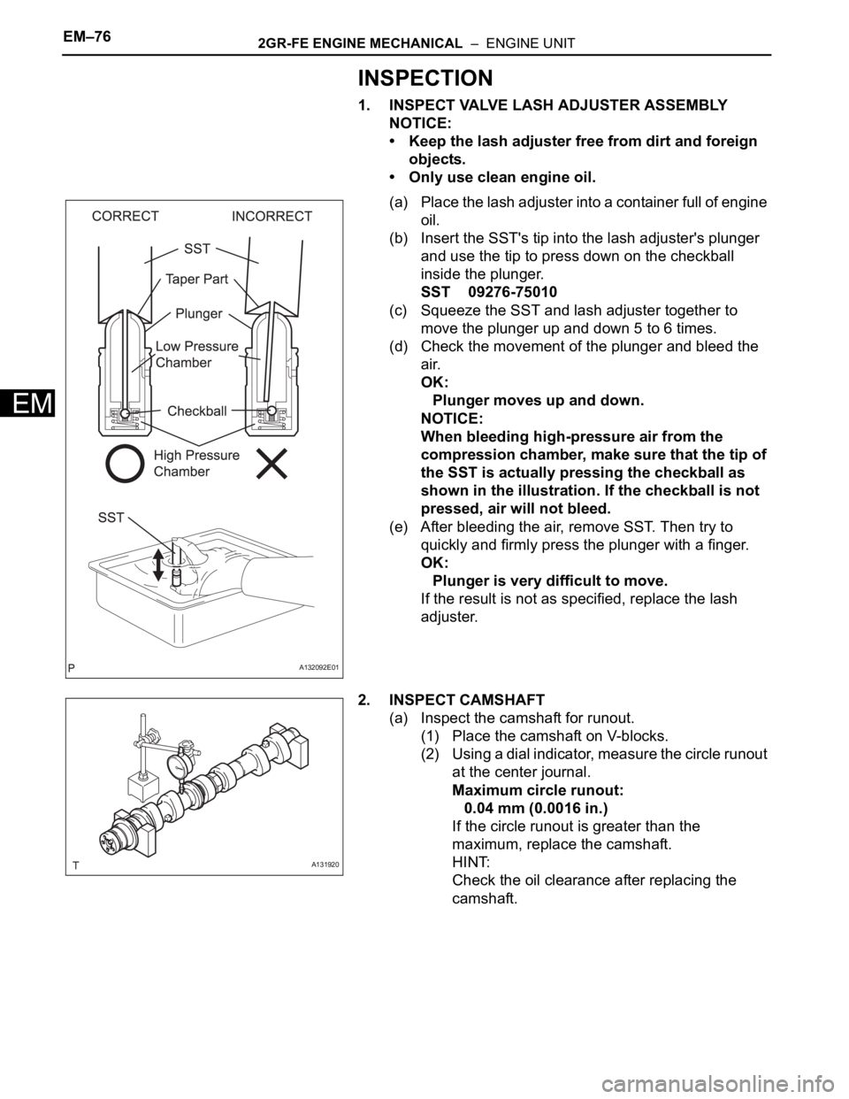
1. INSPECT VALVE LASH ADJUSTER ASSEMBLY
NOTICE:
• Keep the lash adjuster free from dirt and foreign
objects.
• Only use clean engine oil.
(a) Place the lash adjuster into a container full of engine
oil.
(b) Insert the SST's tip into the lash adjuster's plunger
and use the tip to press down on the checkball
inside the plunger.
SST 09276-75010
(c) Squeeze the SST and lash adjuster together to
move the plunger up and down 5 to 6 times.
(d) Check the movement of the plunger and bleed the
air.
OK:
Plunger moves up and down.
NOTICE:
When bleeding high-pressure air from the
compression chamber, make sure that the tip of
the SST is actually pressing the checkball as
shown in the illustration. If the checkball is not
pressed, air will not bleed.
(e) After bleeding the air, remove SST. Then try to
quickly and firmly press the plunger with a finger.
OK:
Plunger is very difficult to move.
If the result is not as specified, replace the lash
adjuster.
2. INSPECT CAMSHAFT
(a) Inspect the camshaft for runout.
(1) Place the camshaft on V-blocks.
(2) Using a dial indicator, measure the circle runout
at the center journal.
Maximum circle runout:
0.04 mm (0.0016 in.)
If the circle runout is greater than the
maximum, replace the camshaft.
HINT:
Check the oil clearance after replacing the
camshaft.
A132092E01
A131920
Page 715 of 2000
EM–782GR-FE ENGINE MECHANICAL – ENGINE UNIT
EM
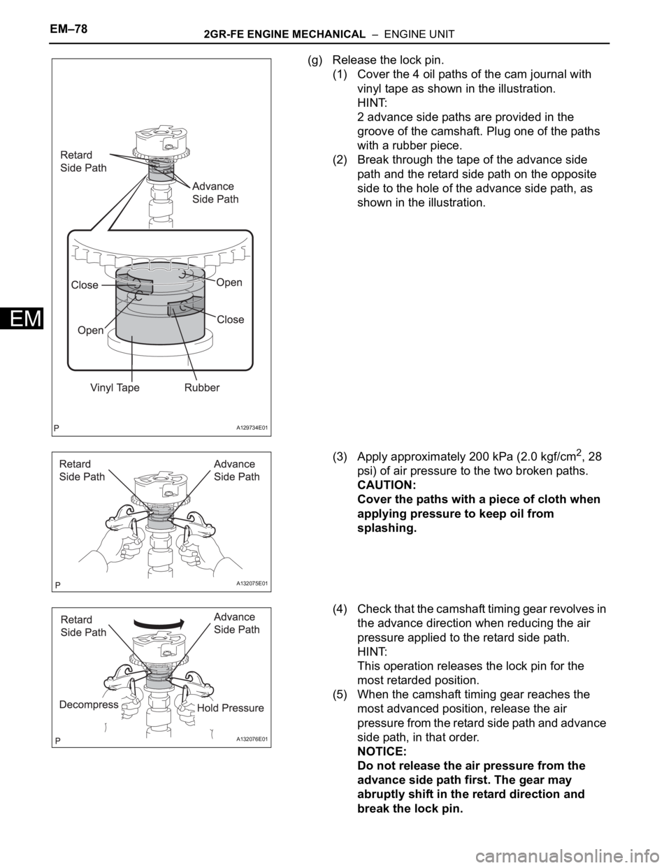
(g) Release the lock pin.
(1) Cover the 4 oil paths of the cam journal with
vinyl tape as shown in the illustration.
HINT:
2 advance side paths are provided in the
groove of the camshaft. Plug one of the paths
with a rubber piece.
(2) Break through the tape of the advance side
path and the retard side path on the opposite
side to the hole of the advance side path, as
shown in the illustration.
(3) Apply approximately 200 kPa (2.0 kgf/cm
2, 28
psi) of air pressure to the two broken paths.
CAUTION:
Cover the paths with a piece of cloth when
applying pressure to keep oil from
splashing.
(4) Check that the camshaft timing gear revolves in
the advance direction when reducing the air
pressure applied to the retard side path.
HINT:
This operation releases the lock pin for the
most retarded position.
(5) When the camshaft timing gear reaches the
most advanced position, release the air
pressure from the retard side path and advance
side path, in that order.
NOTICE:
Do not release the air pressure from the
advance side path first. The gear may
abruptly shift in the retard direction and
break the lock pin.
A129734E01
A132075E01
A132076E01
Page 717 of 2000
EM–802GR-FE ENGINE MECHANICAL – ENGINE UNIT
EM
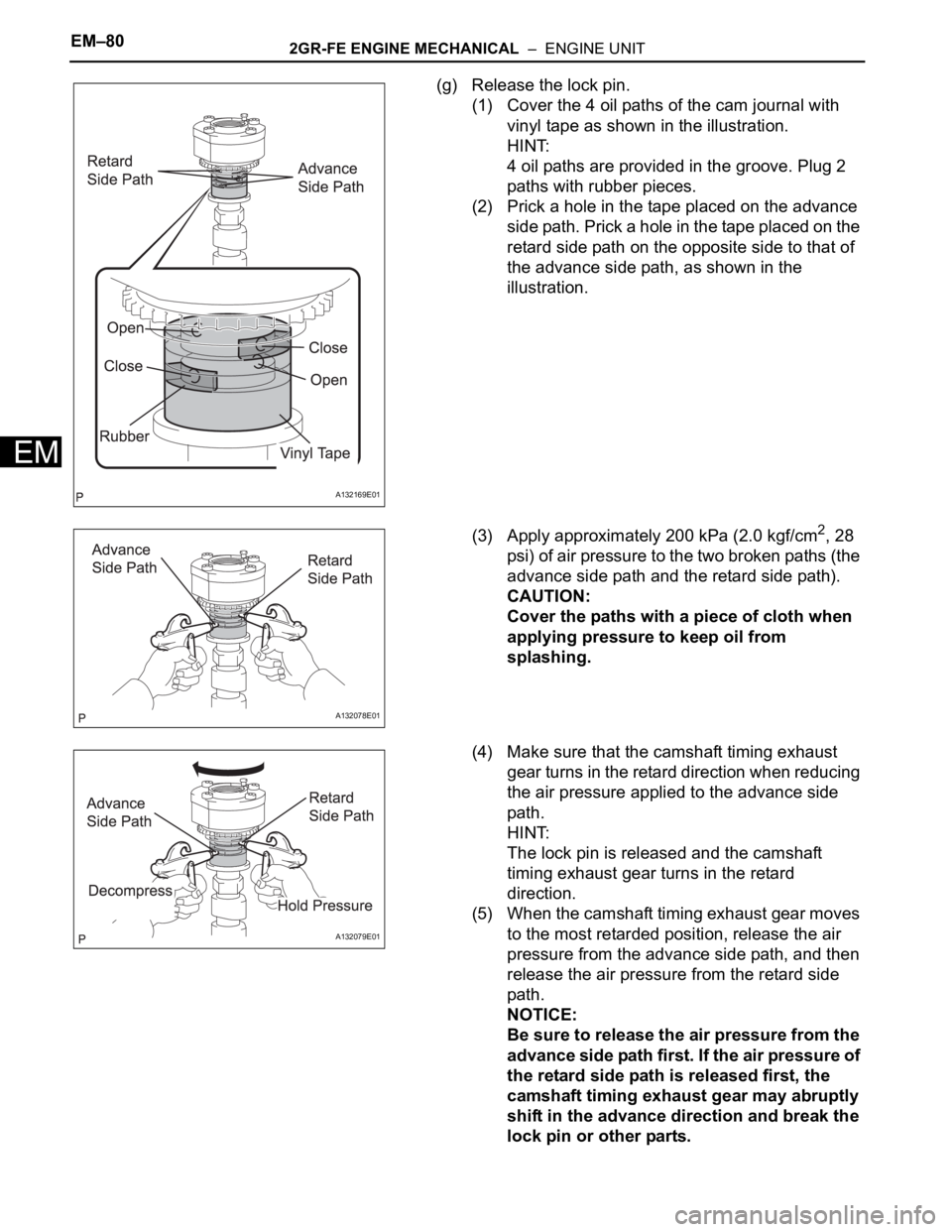
(g) Release the lock pin.
(1) Cover the 4 oil paths of the cam journal with
vinyl tape as shown in the illustration.
HINT:
4 oil paths are provided in the groove. Plug 2
paths with rubber pieces.
(2) Prick a hole in the tape placed on the advance
side path. Prick a hole in the tape placed on the
retard side path on the opposite side to that of
the advance side path, as shown in the
illustration.
(3) Apply approximately 200 kPa (2.0 kgf/cm
2, 28
psi) of air pressure to the two broken paths (the
advance side path and the retard side path).
CAUTION:
Cover the paths with a piece of cloth when
applying pressure to keep oil from
splashing.
(4) Make sure that the camshaft timing exhaust
gear turns in the retard direction when reducing
the air pressure applied to the advance side
path.
HINT:
The lock pin is released and the camshaft
timing exhaust gear turns in the retard
direction.
(5) When the camshaft timing exhaust gear moves
to the most retarded position, release the air
pressure from the advance side path, and then
release the air pressure from the retard side
path.
NOTICE:
Be sure to release the air pressure from the
advance side path first. If the air pressure of
the retard side path is released first, the
camshaft timing exhaust gear may abruptly
shift in the advance direction and break the
lock pin or other parts.
A132169E01
A132078E01
A132079E01
Page 783 of 2000
2AZ-FE FUEL – FUEL PRESSURE PULSATION DAMPERFU–27
FU
REMOVAL
1. DISCHARGE FUEL SYSTEM PRESSURE (See page
FU-9)
2. DISCONNECT CABLE FROM NEGATIVE BATTERY
TERMINAL
3. REMOVE NO. 1 ENGINE COVER (See page ES-410)
4. REMOVE AIR CLEANER CAP SUB-ASSEMBLY (See
page ES-411)
5. DISCONNECT FUEL MAIN TUBE (See page FU-10)
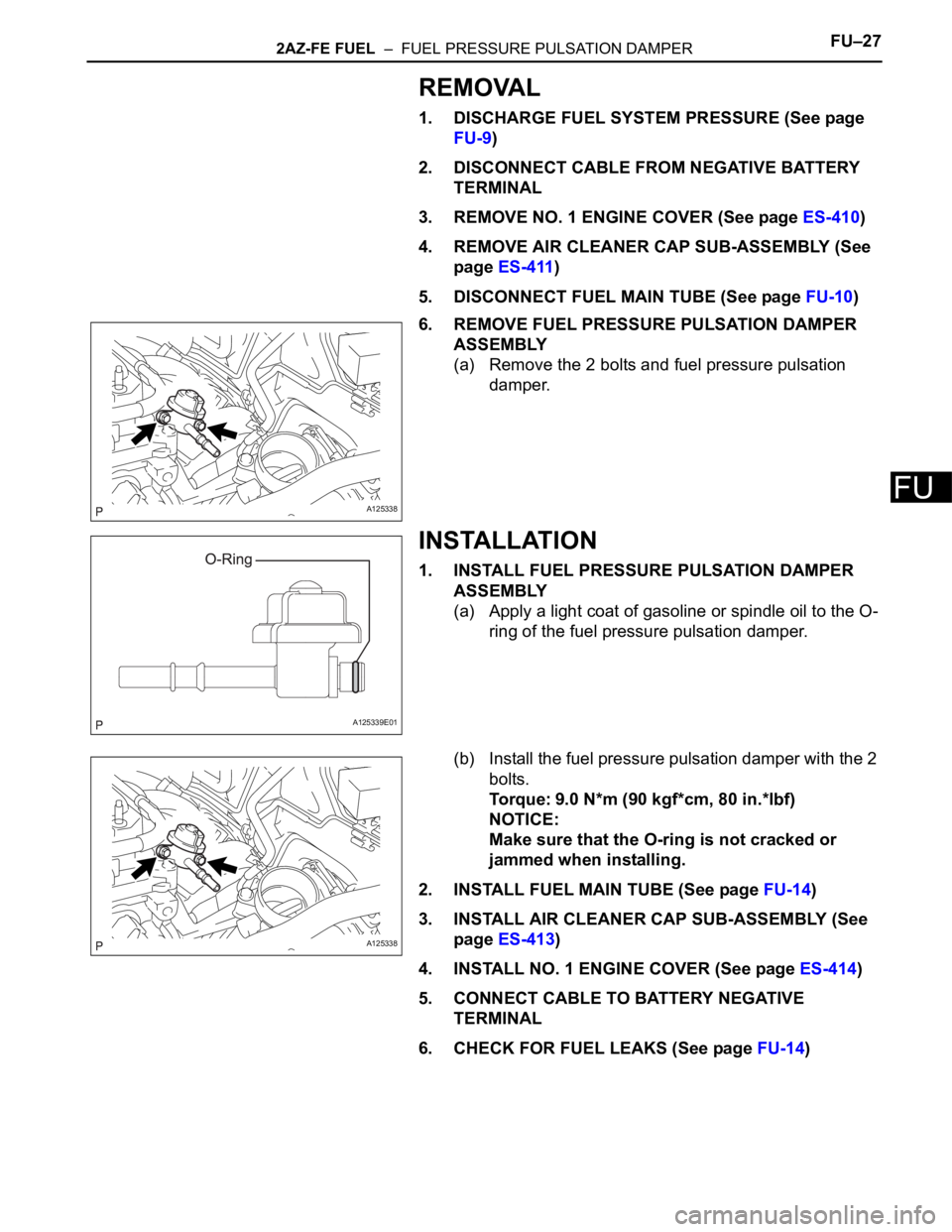
6. REMOVE FUEL PRESSURE PULSATION DAMPER
ASSEMBLY
(a) Remove the 2 bolts and fuel pressure pulsation
damper.
INSTALLATION
1. INSTALL FUEL PRESSURE PULSATION DAMPER
ASSEMBLY
(a) Apply a light coat of gasoline or spindle oil to the O-
ring of the fuel pressure pulsation damper.
(b) Install the fuel pressure pulsation damper with the 2
bolts.
Torque: 9.0 N*m (90 kgf*cm, 80 in.*lbf)
NOTICE:
Make sure that the O-ring is not cracked or
jammed when installing.
2. INSTALL FUEL MAIN TUBE (See page FU-14)
3. INSTALL AIR CLEANER CAP SUB-ASSEMBLY (See
page ES-413)
4. INSTALL NO. 1 ENGINE COVER (See page ES-414)
5. CONNECT CABLE TO BATTERY NEGATIVE
TERMINAL
6. CHECK FOR FUEL LEAKS (See page FU-14)
A125338
A125339E01
A125338