2006 TOYOTA RAV4 ignition
[x] Cancel search: ignitionPage 1493 of 2000
TIRE AND WHEEL – TIRE PRESSURE WARNING SYSTEMTW–21
TW
(c) Test mode
(1) By switching from normal mode to test mode
(input signal check), you can inspect the tire
pressure monitor receiver, each tire pressure
warning valve and transmitter and vehicle speed
sensor (see page TW-12).
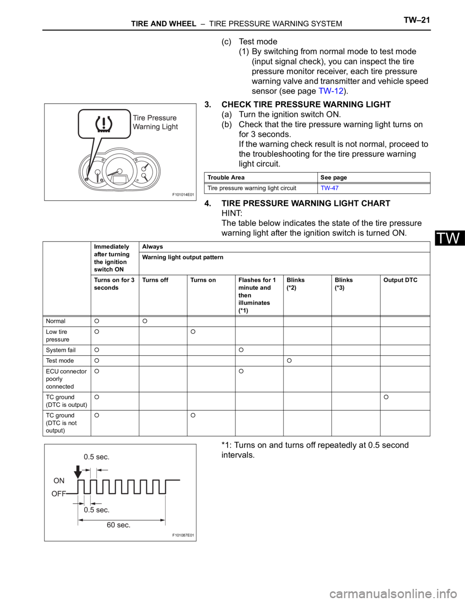
3. CHECK TIRE PRESSURE WARNING LIGHT
(a) Turn the ignition switch ON.
(b) Check that the tire pressure warning light turns on
for 3 seconds.
If the warning check result is not normal, proceed to
the troubleshooting for the tire pressure warning
light circuit.
4. TIRE PRESSURE WARNING LIGHT CHART
HINT:
The table below indicates the state of the tire pressure
warning light after the ignition switch is turned ON.
*1: Turns on and turns off repeatedly at 0.5 second
intervals.
F101014E01
Trouble Area See page
Tire pressure warning light circuitTW-47
Immediately
after turning
the ignition
switch ONAlways
Warning light output pattern
Turns on for 3
secondsTurns off Turns on Flashes for 1
minute and
then
illuminates
(*1)Blinks
(*2)Blinks
(*3)Output DTC
Normal
Low tire
pressure
System fail
Te s t m o d e
ECU connector
poorly
connected
TC ground
(DTC is output)
TC ground
(DTC is not
output)
F101087E01
Page 1494 of 2000
TW–22TIRE AND WHEEL – TIRE PRESSURE WARNING SYSTEM
TW
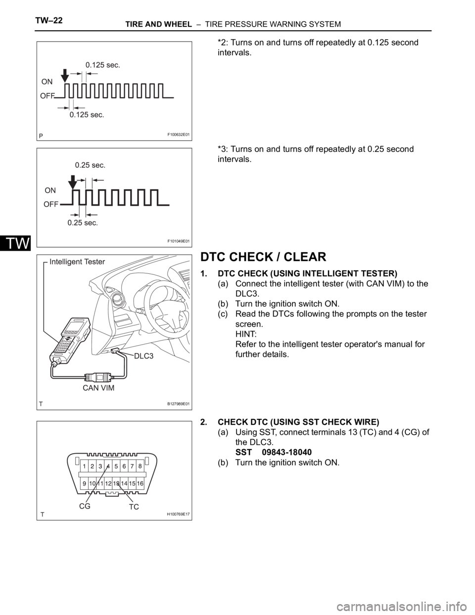
*2: Turns on and turns off repeatedly at 0.125 second
intervals.
*3: Turns on and turns off repeatedly at 0.25 second
intervals.
DTC CHECK / CLEAR
1. DTC CHECK (USING INTELLIGENT TESTER)
(a) Connect the intelligent tester (with CAN VIM) to the
DLC3.
(b) Turn the ignition switch ON.
(c) Read the DTCs following the prompts on the tester
screen.
HINT:
Refer to the intelligent tester operator's manual for
further details.
2. CHECK DTC (USING SST CHECK WIRE)
(a) Using SST, connect terminals 13 (TC) and 4 (CG) of
the DLC3.
SST 09843-18040
(b) Turn the ignition switch ON.
F100632E01
F101049E01
B127989E01
H100769E17
Page 1495 of 2000
TIRE AND WHEEL – TIRE PRESSURE WARNING SYSTEMTW–23
TW
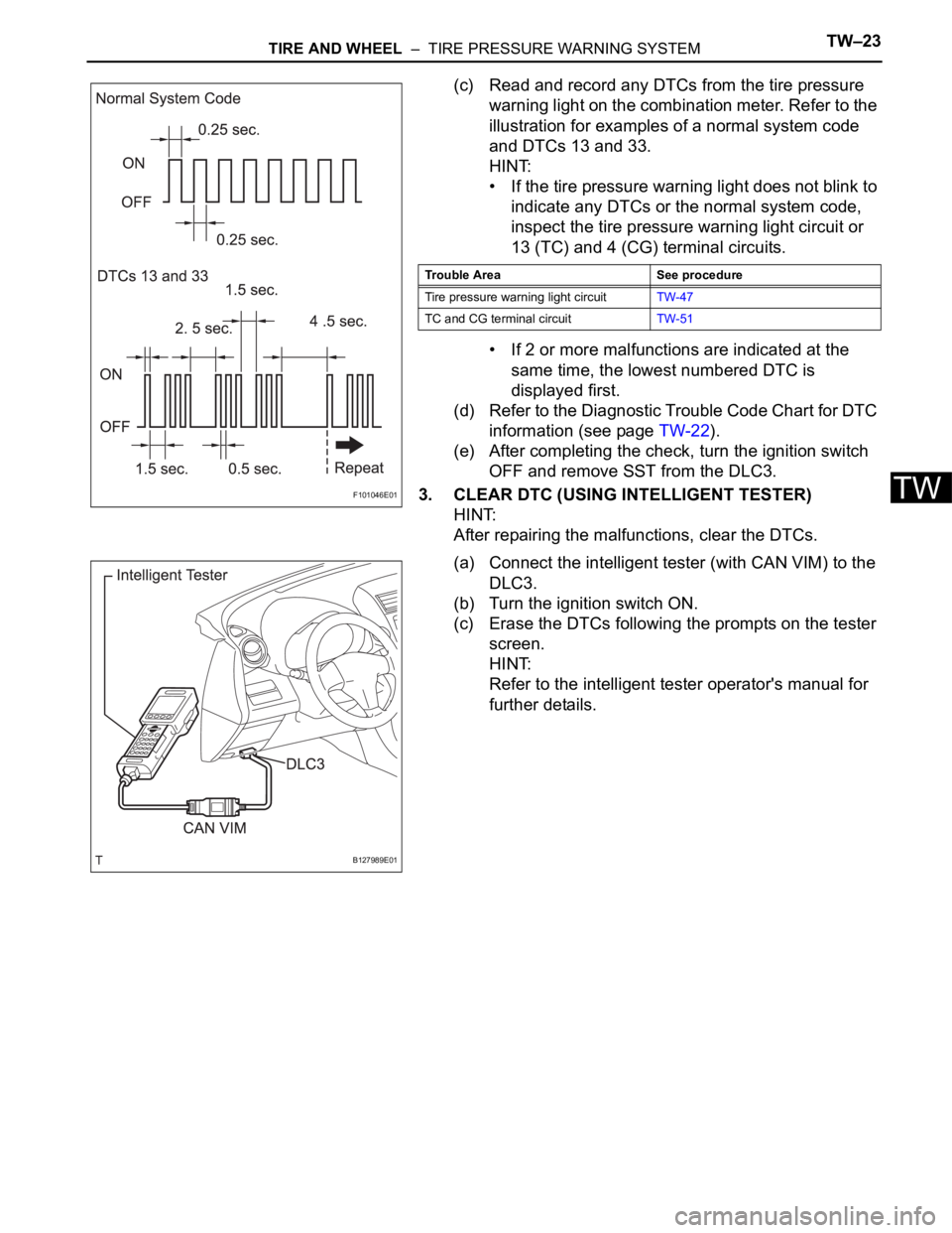
(c) Read and record any DTCs from the tire pressure
warning light on the combination meter. Refer to the
illustration for examples of a normal system code
and DTCs 13 and 33.
HINT:
• If the tire pressure warning light does not blink to
indicate any DTCs or the normal system code,
inspect the tire pressure warning light circuit or
13 (TC) and 4 (CG) terminal circuits.
• If 2 or more malfunctions are indicated at the
same time, the lowest numbered DTC is
displayed first.
(d) Refer to the Diagnostic Trouble Code Chart for DTC
information (see page TW-22).
(e) After completing the check, turn the ignition switch
OFF and remove SST from the DLC3.
3. CLEAR DTC (USING INTELLIGENT TESTER)
HINT:
After repairing the malfunctions, clear the DTCs.
(a) Connect the intelligent tester (with CAN VIM) to the
DLC3.
(b) Turn the ignition switch ON.
(c) Erase the DTCs following the prompts on the tester
screen.
HINT:
Refer to the intelligent tester operator's manual for
further details.
F101046E01
Trouble Area See procedure
Tire pressure warning light circuitTW-47
TC and CG terminal circuitTW-51
B127989E01
Page 1496 of 2000

TW–24TIRE AND WHEEL – TIRE PRESSURE WARNING SYSTEM
TW
DATA LIST / ACTIVE TEST
1. READ DATA LIST
HINT:
Using the intelligent tester's DATA LIST allows switch,
actuator and other item values to be read without
removing any parts. Reading the Data List early in
troubleshooting is one way to save time.
(a) Connect the intelligent tester (with CAN VIM) to the
DLC3.
(b) Turn the ignition switch ON.
(c) Read the DATA LIST according to the display on the
tester.
Tire pressure warning ECU
Item Measurement item/ Range
(Display)Normal Condition Diagnostic Note
MODE STATUS Tire pressure warning system
mode / NORMAL or REG 2nd or
REG M or TEST NORMAL: Normal mode TEST:
Test mode
REG 2nd: 2nd registration
REG M: Main registration
TEST: Test mode -
MAIN TIRE Number of main tire IDs to be
registered / 0 or 1 or 2 or 3 or 4
or 5 0 to 5 should be displayed -
VEHICLE SPEED Vehicle speed reading /
min.: 0 km/h (0 mph),
max.: 255 km/h (158 mph)Actual vehicle speed Speed indicated on the
combination meter
REGIT ID1 CODE Registered ID1 code / min.: 0,
max.: FFFFFFF The ID No. registered in
transmitter ID1 is displayed -
REGIT ID2 CODE Registered ID2 code / min.: 0,
max.: FFFFFFF The ID No. registered in
transmitter ID2 is displayed -
REGIT ID3 CODE Registered ID3 code / min.: 0,
max.: FFFFFFF The ID No. registered in
transmitter ID3 is displayed -
REGIT ID4 CODE Registered ID4 code / min.: 0,
max.: FFFFFFF The ID No. registered in
transmitter ID4 is displayed -
REGIT ID5 CODE Registered ID5 code / min.: 0,
max.: FFFFFFF The ID No. registered in
transmitter ID5 is displayed -
TRANS STATUS ID code transmission status /
FINISH or NOW FINISH or NOW -
TIREPRESS1 ID1 tire pressure /
min.: 0 kPa (0 kgf/cm
2, 0 psi)
max.: 637.5 kPa (6.48 kgf/cm2,
92.2 psi) Actual tire pressure -
TIREPRESS2 ID2 tire pressure /
min.: 0 kPa (0 kgf/cm
2, 0 psi)
max.: 637.5 kPa (6.48 kgf/cm2,
92.2 psi) Actual tire pressure -
TIREPRESS3 ID3 tire pressure /
min.: 0 kPa (0 kgf/cm
2, 0 psi)
max.: 637.5 kPa (6.48 kgf/cm2,
92.2 psi) Actual tire pressure -
TIREPRESS4 ID4 tire pressure /
min.: 0 kPa (0 kgf/cm
2, 0 psi)
max.: 637.5 kPa (6.48 kgf/cm2,
92.2 psi) Actual tire pressure -
TIREPRESS5 ID5 tire pressure /
min.: 0 kPa (0 kgf/cm
2, 0 psi)
max.: 637.5 kPa (6.48 kgf/cm2,
92.2 psi) Actual tire pressure -
Page 1501 of 2000
TIRE AND WHEEL – TIRE PRESSURE WARNING SYSTEMTW–29
TW
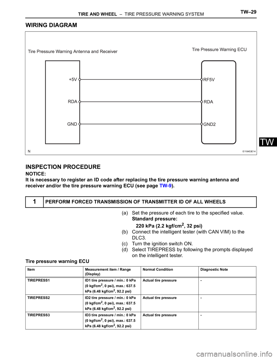
WIRING DIAGRAM
INSPECTION PROCEDURE
NOTICE:
It is necessary to register an ID code after replacing the tire pressure warning antenna and
receiver and/or the tire pressure warning ECU (see page TW-9).
(a) Set the pressure of each tire to the specified value.
Standard pressure:
220 kPa (2.2 kgf/cm
2, 32 psi)
(b) Connect the intelligent tester (with CAN VIM) to the
DLC3.
(c) Turn the ignition switch ON.
(d) Select TIREPRESS by following the prompts displayed
on the intelligent tester.
Tire pressure warning ECU
1PERFORM FORCED TRANSMISSION OF TRANSMITTER ID OF ALL WHEELS
E118453E14
Item Measurement item / Range
(Display) Normal Condition Diagnostic Note
TIREPRESS1 ID1 tire pressure / min.: 0 kPa
(0 kgf/cm
2, 0 psi), max.: 637.5
kPa (6.48 kgf/cm2, 92.2 psi) Actual tire pressure -
TIREPRESS2 ID2 tire pressure / min.: 0 kPa
(0 kgf/cm
2, 0 psi), max.: 637.5
kPa (6.48 kgf/cm2, 92.2 psi) Actual tire pressure -
TIREPRESS3 ID3 tire pressure / min.: 0 kPa
(0 kgf/cm
2, 0 psi), max.: 637.5
kPa (6.48 kgf/cm2, 92.2 psi) Actual tire pressure -
Page 1504 of 2000
TW–32TIRE AND WHEEL – TIRE PRESSURE WARNING SYSTEM
TW
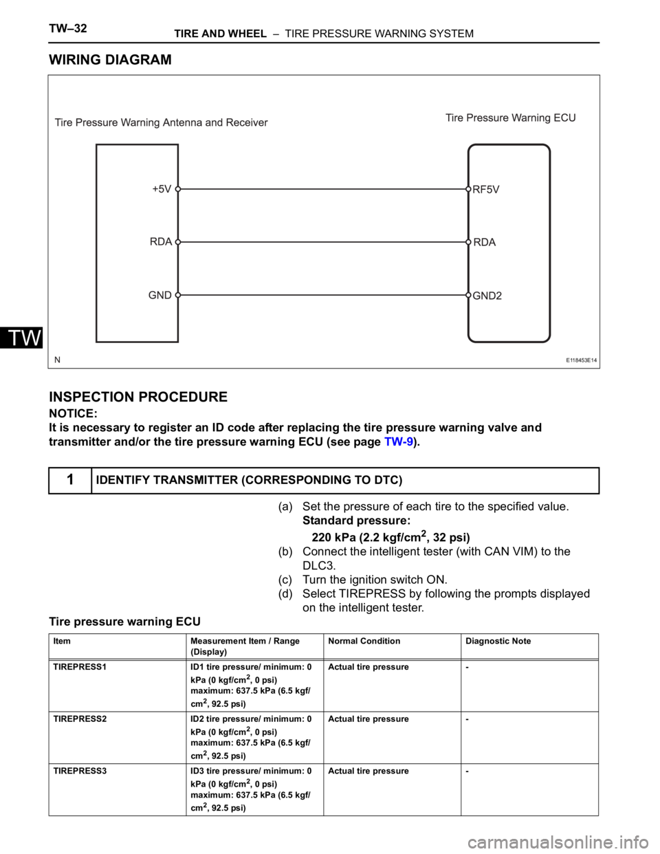
WIRING DIAGRAM
INSPECTION PROCEDURE
NOTICE:
It is necessary to register an ID code after replacing the tire pressure warning valve and
transmitter and/or the tire pressure warning ECU (see page TW-9).
(a) Set the pressure of each tire to the specified value.
Standard pressure:
220 kPa (2.2 kgf/cm
2, 32 psi)
(b) Connect the intelligent tester (with CAN VIM) to the
DLC3.
(c) Turn the ignition switch ON.
(d) Select TIREPRESS by following the prompts displayed
on the intelligent tester.
Tire pressure warning ECU
1IDENTIFY TRANSMITTER (CORRESPONDING TO DTC)
E118453E14
Item Measurement Item / Range
(Display)Normal Condition Diagnostic Note
TIREPRESS1 ID1 tire pressure/ minimum: 0
kPa (0 kgf/cm
2, 0 psi)
maximum: 637.5 kPa (6.5 kgf/
cm
2, 92.5 psi)Actual tire pressure -
TIREPRESS2 ID2 tire pressure/ minimum: 0
kPa (0 kgf/cm
2, 0 psi)
maximum: 637.5 kPa (6.5 kgf/
cm
2, 92.5 psi)Actual tire pressure -
TIREPRESS3 ID3 tire pressure/ minimum: 0
kPa (0 kgf/cm
2, 0 psi)
maximum: 637.5 kPa (6.5 kgf/
cm
2, 92.5 psi)Actual tire pressure -
Page 1522 of 2000

BRAKE CONTROL – VEHICLE STABILITY CONTROL SYSTEMBC–19
BC
4. FAIL SAFE FUNCTION
(a) When a failure occurs in the ABS with BA, TRC and
VSC systems, the ABS and VSC warning lights
illuminate, the slip indicator light comes on*1 or
remains off*2, and the operations of those systems
are prohibited. In addition to this, when a failure
which disables the EBD operation occurs, the brake
warning light comes on and its operation is
prohibited.
HINT:
*1: for 2WD
*2: for 4WD
(b) If control is prohibited due to a malfunction during
operation, control is disabled gradually to avoid
sudden vehicle instability.
5. INITIAL CHECK
(a) When the vehicle speed first reaches approximately
6 km/h (4 mph) or more after the ignition switch is
turned ON, each solenoid valve and the motor of the
ABS and TRACTION actuator are sequentially
activated to perform electrical checks. During the
initial check, the operating sound of the solenoid
valve and motor can be heard from the engine
compartment, but this does not indicate a
malfunction.
6. SERVICE MODE
(a) VSC operation can be disabled by operating the
intelligent tester.
HINT:
Refer to the intelligent tester operator's manual for
further details.
7. FUNCTION OF COMPONENTS
Components Functions
Speed Sensor
(Semiconductor Type)Detects the wheel speed and sends the signal to skid
control ECU
Skid Control ECU
(Housed in ABS and TRACTION Actuator)• Processes the signals from each sensor to control the
ABS, BA, TRC, and VSC
• Sends and receives control signals to and from the
ECM, yaw rate and deceleration sensor, steering
sensor, etc. via CAN communication.
ABS and TRACTION Actuator • Consists of the master cylinder cut solenoid valve,
holding solenoid valve, pressure reduction solenoid
valve, pump motor, and reservoir, and adjusts the brake
fluid pressure applied to each wheel cylinder
• Houses the skid control ECU
Solenoid Relay • Supplies power to each solenoid
• Housed in the skid control ECU
Motor Relay (VSC MTR Relay) • Supplies power to the pump motor
• Installed in engine room No. 1 relay block
Fail-safe Relay (VSC FAIL Relay) • Cuts off power to the motor when the pump motor circuit
malfunctions
• Installed in engine room No. 1 relay block
Page 1527 of 2000
BC–24BRAKE CONTROL – VEHICLE STABILITY CONTROL SYSTEM
BC
CHECK FOR INTERMITTENT
PROBLEMS
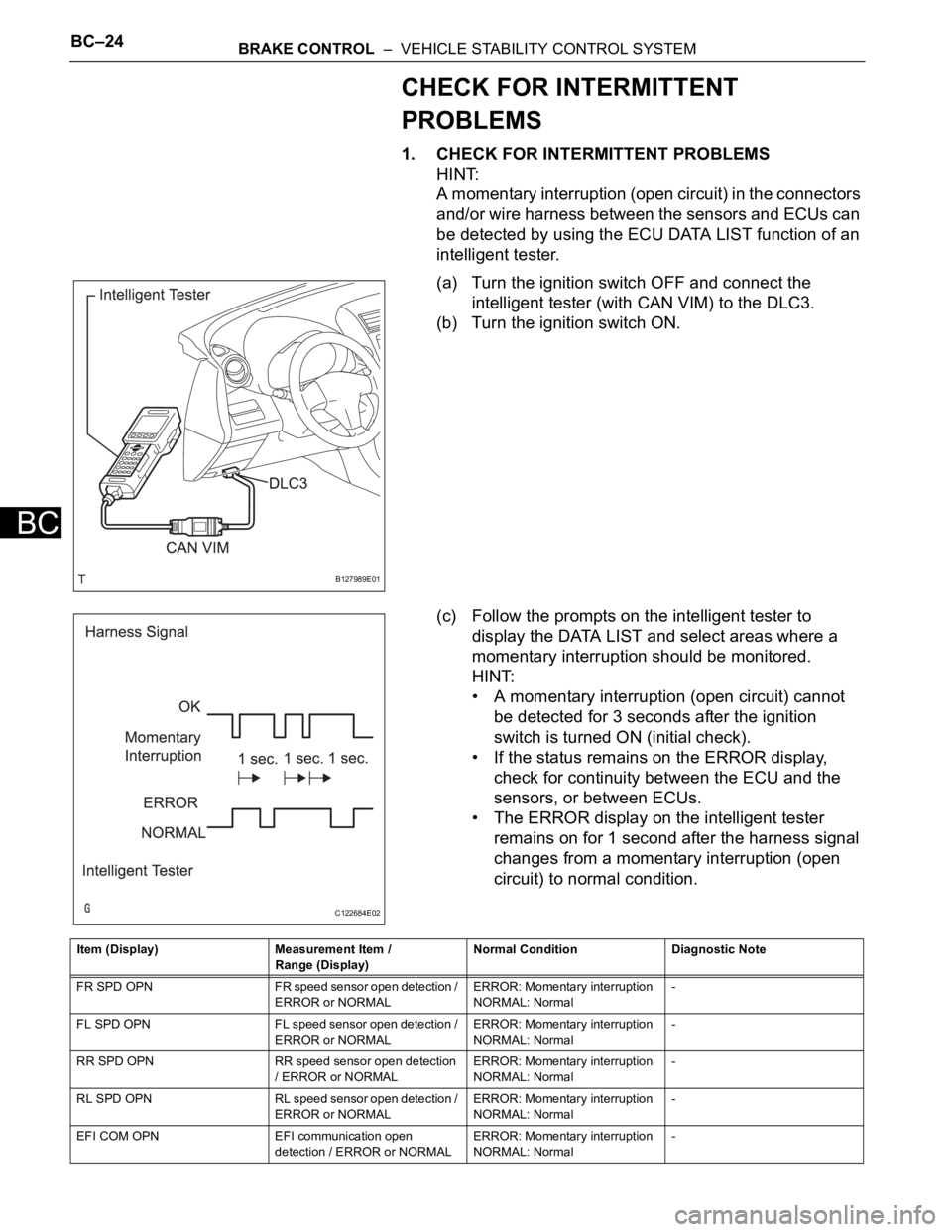
1. CHECK FOR INTERMITTENT PROBLEMS
HINT:
A momentary interruption (open circuit) in the connectors
and/or wire harness between the sensors and ECUs can
be detected by using the ECU DATA LIST function of an
intelligent tester.
(a) Turn the ignition switch OFF and connect the
intelligent tester (with CAN VIM) to the DLC3.
(b) Turn the ignition switch ON.
(c) Follow the prompts on the intelligent tester to
display the DATA LIST and select areas where a
momentary interruption should be monitored.
HINT:
• A momentary interruption (open circuit) cannot
be detected for 3 seconds after the ignition
switch is turned ON (initial check).
• If the status remains on the ERROR display,
check for continuity between the ECU and the
sensors, or between ECUs.
• The ERROR display on the intelligent tester
remains on for 1 second after the harness signal
changes from a momentary interruption (open
circuit) to normal condition.
B127989E01
C122684E02
Item (Display) Measurement Item /
Range (Display)Normal Condition Diagnostic Note
FR SPD OPN FR speed sensor open detection /
ERROR or NORMALERROR: Momentary interruption
NORMAL: Normal-
FL SPD OPN FL speed sensor open detection /
ERROR or NORMALERROR: Momentary interruption
NORMAL: Normal-
RR SPD OPN RR speed sensor open detection
/ ERROR or NORMALERROR: Momentary interruption
NORMAL: Normal-
RL SPD OPN RL speed sensor open detection /
ERROR or NORMALERROR: Momentary interruption
NORMAL: Normal-
EFI COM OPN EFI communication open
detection / ERROR or NORMALERROR: Momentary interruption
NORMAL: Normal-