Page 1359 of 2000

GF1A TRANSFER – ACTIVE TORQUE CONTROL 4WD SYSTEMTF–31
TF
(e) Drive the vehicle and turn the steering wheel to the right
and left at a speed of 35 km/h (24 mph) and check that
no brake control system (steering angle sensor) DTC
(C1231/31) is output (see page BC-57).
Result
HINT:
When DTCs indicating a CAN communication system
malfunction are output, repair the CAN communication
system before repairing each corresponding sensor.
B
C
A
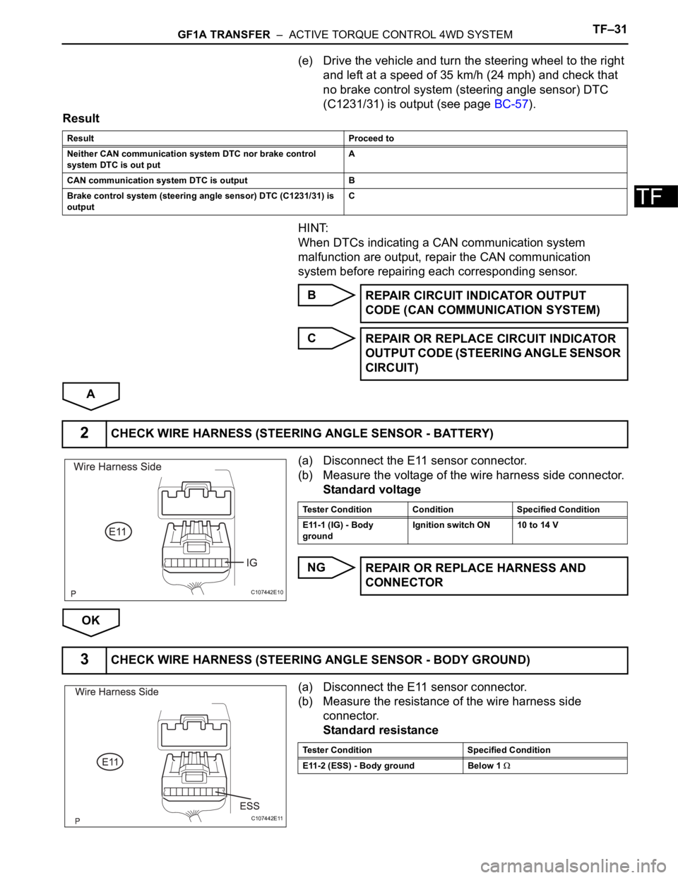
(a) Disconnect the E11 sensor connector.
(b) Measure the voltage of the wire harness side connector.
Standard voltage
NG
OK
(a) Disconnect the E11 sensor connector.
(b) Measure the resistance of the wire harness side
connector.
Standard resistance
Result Proceed to
Neither CAN communication system DTC nor brake control
system DTC is out putA
CAN communication system DTC is output B
Brake control system (steering angle sensor) DTC (C1231/31) is
output C
REPAIR CIRCUIT INDICATOR OUTPUT
CODE (CAN COMMUNICATION SYSTEM)
REPAIR OR REPLACE CIRCUIT INDICATOR
OUTPUT CODE (STEERING ANGLE SENSOR
CIRCUIT)
2CHECK WIRE HARNESS (STEERING ANGLE SENSOR - BATTERY)
C107442E10
Tester Condition Condition Specified Condition
E11-1 (IG) - Body
groundIgnition switch ON 10 to 14 V
REPAIR OR REPLACE HARNESS AND
CONNECTOR
3CHECK WIRE HARNESS (STEERING ANGLE SENSOR - BODY GROUND)
C107442E11
Tester Condition Specified Condition
E11-2 (ESS) - Body ground Below 1
Page 1482 of 2000

TW–10TIRE AND WHEEL – TIRE PRESSURE WARNING SYSTEM
TW
REGISTRATION
1. IN CASE OF TIRE PRESSURE WARNING ECU
REPLACEMENT
(a) Read ID stored in the old ECU using the intelligent
tester.
2. IN CASE OF TIRE PRESSURE WARNING VALVE AND
TRANSMITTER AND/OR TIRE PRESSURE WARNING
ECU REPLACEMENT
(a) Read the ID written on the tire pressure monitor
valve.
3. REGISTER TRANSMITTER ID
NOTICE:
It is necessary to register the transmitter ID in the
tire pressure warning ECU when replacing the tire
pressure warning valve and transmitter and/or tire
pressure warning ECU.
(a) Prepare all of the transmitter ID data before starting
registration.
HINT:
• Read the registered transmitter IDs that are
stored in the ECU using the intelligent tester and
make a note of them.
• If reading stored transmitter IDs is impossible
due to malfunctions of components such as the
tire pressure warning antenna and receiver,
remove the tires from the wheels and check the
IDs located on the tire pressure warning valves
and transmitters (see page TW-60).
• When replacing the tire pressure warning valves
and transmitters, make a note of the IDs written
on the tire pressure warning valves and
transmitters.
(b) Connect the intelligent tester (with CAN VIM) to the
DLC3.
(c) Turn the ignition switch ON.
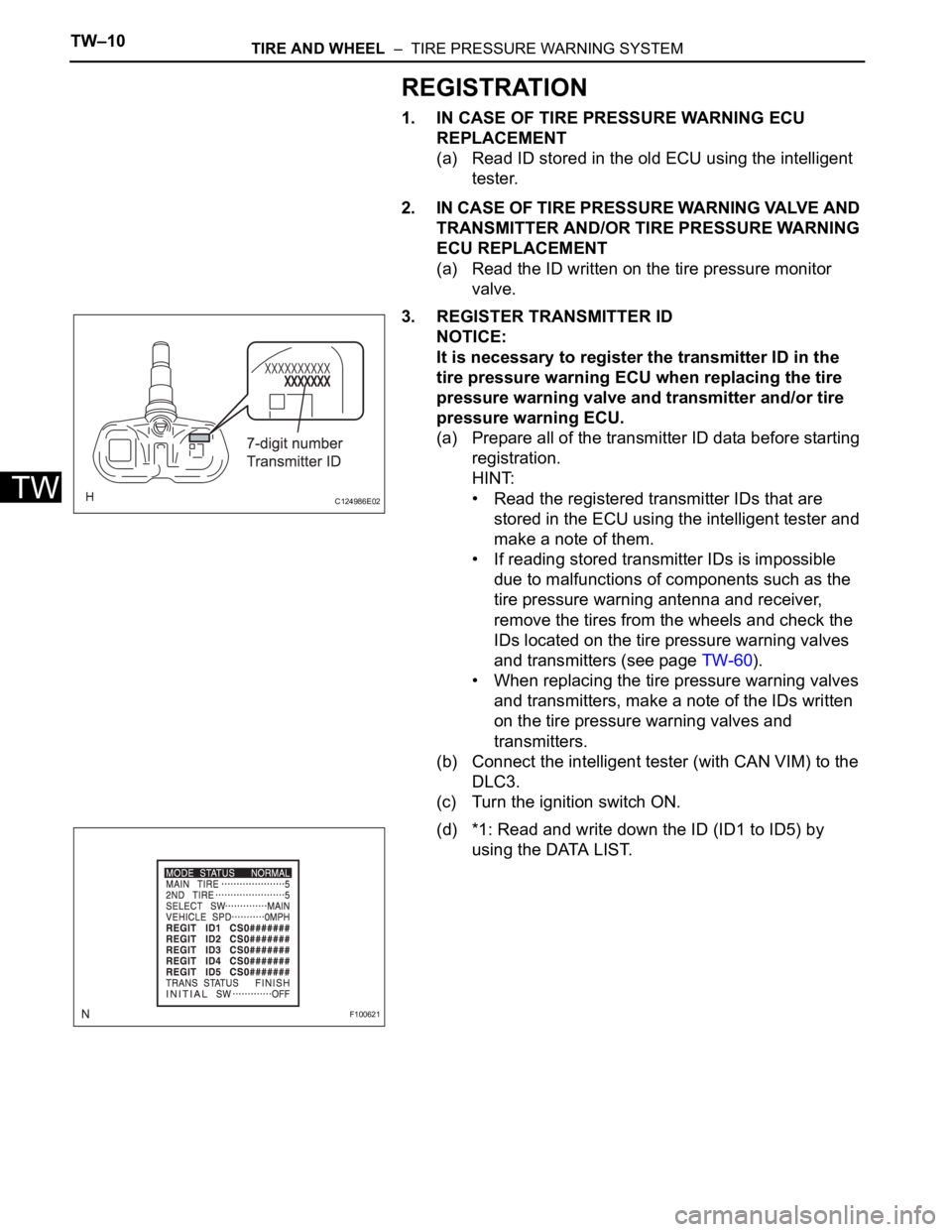
(d) *1: Read and write down the ID (ID1 to ID5) by
using the DATA LIST.
C124986E02
F100621
Page 1485 of 2000
TIRE AND WHEEL – TIRE PRESSURE WARNING SYSTEMTW–13
TW
(b) Connect the intelligent tester (with CAN VIM ) to the
DLC3.
(c) Turn the ignition switch ON.
(d) Select "SIGNAL CHECK" mode on the intelligent
tester (with CAN VIM ) (see page TW-12).
(e) Confirm that the transmitter IDs and tire pressure
data for all the tires are displayed on the intelligent
tester screen.
NOTICE:
• It may take up to 1 minute to update the tire
pressure data.
• If the IDs have not been registered, DTC
C2171/71 is set in the tire pressure warning
ECU after approximately 60 minutes.
Page 1486 of 2000
TW–14TIRE AND WHEEL – TIRE PRESSURE WARNING SYSTEM
TW
TEST MODE PROCEDURE
1. TEST MODE CHECK
HINT:
• When entering the TEST MODE, the tire pressure
warning ECU sets all the test DTCs first. After
completing the test mode for each inspection item, the
DTCs that are determined normal by the tire pressure
warning ECU will be erased.
The DTCs for other inspection items may not be
erased when only a certain signal is inspected.
• When the test mode returns back to the normal mode,
all the test DTCs will be erased.
(a) Make sure that the ignition switch is OFF.
(b) Connect the intelligent tester (with CAN VIM) to the
DLC3.
(c) Turn the ignition switch ON.
(d) Select TEST MODE on the intelligent tester.
B127989E01
C122887
Page 1487 of 2000
TIRE AND WHEEL – TIRE PRESSURE WARNING SYSTEMTW–15
TW
(e) Confirm that the tire pressure warning light in the
combination meter blinks at 0.125 second intervals.
2. PERFORM SIGNAL CHECK
HINT:
• When entering the signal check, the tire pressure
warning ECU sets all the signal check DTCs first.
After completing the signal check for each inspection
item, the DTCs that are determined normal by the tire
pressure warning ECU will be erased. The DTCs for
other inspection items may not be erased when only a
certain signal is inspected.
• When the signal check returns back to normal mode,
all the signal check DTCs will be erased.
(a) Make sure that the ignition switch is OFF.
(b) Connect the intelligent tester (with CAN VIM ) to the
DLC3.
(c) Turn the ignition switch ON.
(d) Select SIGNAL CHECK on the intelligent tester.
(e) Drive the vehicle at 12 mph (20 km/h) or more for 10
seconds or more .
F100632E01
B127989E01
Page 1488 of 2000
TW–16TIRE AND WHEEL – TIRE PRESSURE WARNING SYSTEM
TW
(f) Loosen the valve core and rapidly reduce the
pressure (above 40 kPa / 30 seconds or more).
HINT:
The transmitter ID can be transmitted by rapidly
reducing the tire pressure.
(g) Result
HINT:
After the signal check is completed, check for a
DTC and signal check DTC to confirm the system
status.
(h) End of SIGNAL CHECK
After completing test mode (SIGNAL CHECK), turn
the ignition switch OFF and disconnect the tester.
DTC of SIGNAL CHECK (TEST DIAGNOSIS)
function:
If a malfunction code is displayed during the
test mode DTC check, check the circuit listed
for that code. For details of each code, refer to
the "see page" of the "DTC No." in the chart.
F101084
Condition Procedure
SIGNAL CHECK DTC is output Repair faulty part and enter SIGNAL CHECK again
SIGNAL CHECK DTCs are cleared No problem
Page 1491 of 2000

TIRE AND WHEEL – TIRE PRESSURE WARNING SYSTEMTW–19
TW
TERMINALS OF ECU
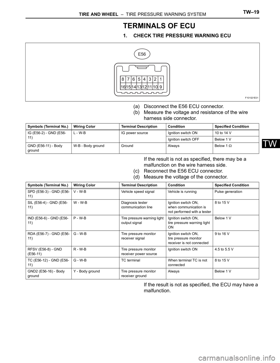
1. CHECK TIRE PRESSURE WARNING ECU
(a) Disconnect the E56 ECU connector.
(b) Measure the voltage and resistance of the wire
harness side connector.
If the result is not as specified, there may be a
malfunction on the wire harness side.
(c) Reconnect the E56 ECU connector.
(d) Measure the voltage of the connector.
If the result is not as specified, the ECU may have a
malfunction.
F101021E01
Symbols (Terminal No.) Wiring Color Terminal Description ConditionSpecified Condition
IG (E56-2) - GND (E56-
11 )L - W-B IG power source Ignition switch ON 10 to 14 V
Ignition switch OFF Below 1 V
GND (E56-11) - Body
groundW-B - Body ground Ground Always Below 1
Symbols (Terminal No.) Wiring Color Terminal Description ConditionSpecified Condition
SPD (E56-3) - GND (E56-
11 )V - W-B Vehicle speed signal Vehicle is running Pulse generation
SIL (E56-4) - GND (E56-
11 )W - W-B Diagnosis tester
communication lineIgnition switch ON,
when communication is
not performed with a tester8 to 15 V
IND (E56-6) - GND (E56-
11 )P - W-B Tire pressure warning light
output signalIgnition switch ON,
tire pressure warning light
ONBelow 1 V
RDA (E56-7) - GND (E56-
11 )G - W-B Tire pressure monitor
receiver signalIgnition switch ON,
tire pressure monitor
receiver is not connected9 to 16 V
RFSV (E56-8) - GND
(E56-11)R - W-B Tire pressure monitor
receiver power sourceIgnition switch ON 4.5 to 5.5 V
TC (E56-12) - GND (E56-
11 )G - W-B TC terminal When terminal TC is not
connected8 to 15 V
GND2 (E56-16) - Body
groundY - Body ground Tire pressure monitor
receiver groundAlways Below 1 V
Page 1492 of 2000

TW–20TIRE AND WHEEL – TIRE PRESSURE WARNING SYSTEM
TW
DIAGNOSIS SYSTEM
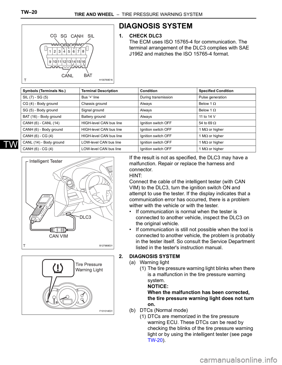
1. CHECK DLC3
The ECM uses ISO 15765-4 for communication. The
terminal arrangement of the DLC3 complies with SAE
J1962 and matches the ISO 15765-4 format.
If the result is not as specified, the DLC3 may have a
malfunction. Repair or replace the harness and
connector.
HINT:
Connect the cable of the intelligent tester (with CAN
VIM) to the DLC3, turn the ignition switch ON and
attempt to use the tester. If the display indicates that a
communication error has occurred, there is a problem
wither with the vehicle or with the tester.
• If communication is normal when the tester is
connected to another vehicle, inspect the DLC3 on
the original vehicle.
• If communication is still not possible when the tool is
connected to another vehicle, the problem is probably
in the tester itself. So consult the Service Department
listed in the tester's instruction manual.
2. DIAGNOSIS SYSTEM
(a) Warning light
(1) The tire pressure warning light blinks when there
is a malfunction in the tire pressure warning
system.
NOTICE:
When the malfunction has been corrected,
the tire pressure warning light does not turn
on.
(b) DTCs (Normal mode)
(1) DTCs are memorized in the tire pressure
warning ECU. These DTCs can be read by
checking the blinks of the tire pressure warning
light or by using the intelligent tester (see page
TW-20).
H100769E16
Symbols (Terminals No.) Terminal Description Condition Specified Condition
SIL (7) - SG (5) Bus '+' line During transmission Pulse generation
CG (4) - Body ground Chassis ground Always Below 1
SG (5) - Body ground Signal ground Always Below 1
BAT (16) - Body ground Battery ground Always 11 to 14 V
CANH (6) - CANL (14) HIGH-level CAN bus line Ignition switch OFF 54 to 69
CANH (6) - Body ground HIGH-level CAN bus line Ignition switch OFF1 M or higher
CANH (6) - CG (4) HIGH-level CAN bus line Ignition switch OFF 1 M
or higher
CANL (14) - Body ground LOW-level CAN bus line Ignition switch OFF1 M
or higher
CANH (6) - CG (4) LOW-level CAN bus line Ignition switch OFF 1 M
or higher
B127989E01
F101014E01