2006 TOYOTA RAV4 ignition
[x] Cancel search: ignitionPage 1055 of 2000
U151E AUTOMATIC TRANSAXLE – FLOOR SHIFT ASSEMBLYAX–165
AX
ADJUSTMENT
1. INSPECT SHIFT LEVER POSITION
(a) When shifting the lever from P to the R position with
the ignition switch ON and the brake pedal
depressed, make sure that the shift lever moves
smoothly and moves correctly into position.
(b) Start the engine and make sure that the vehicle
moves forward when shifting the lever from N to the
D position and moves rearward when shifting the
lever to the R position.
If the operation cannot be performed as specified,
inspect the park/neutral position switch assembly
and check the shift lever assembly installation
condition.
2. ADJUST SHIFT LEVER POSITION
(a) Shift the shift lever to the N position.
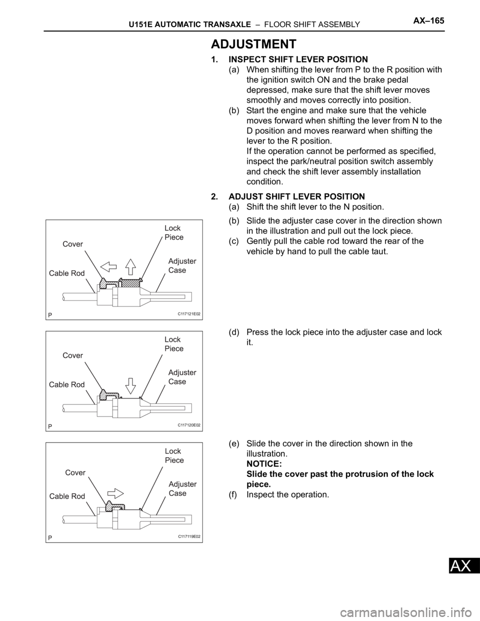
(b) Slide the adjuster case cover in the direction shown
in the illustration and pull out the lock piece.
(c) Gently pull the cable rod toward the rear of the
vehicle by hand to pull the cable taut.
(d) Press the lock piece into the adjuster case and lock
it.
(e) Slide the cover in the direction shown in the
illustration.
NOTICE:
Slide the cover past the protrusion of the lock
piece.
(f) Inspect the operation.
C117121E02
C117120E02
C117119E02
Page 1139 of 2000
AX–20U151F AUTOMATIC TRANSAXLE – AUTOMATIC TRANSAXLE SYSTEM
AX
HYDRAULIC TEST
1. PERFORM HYDRAULIC TEST
(a) Measure the line pressure.
NOTICE:
• Perform the test at the normal operating ATF
temperature: 50 to 80
C (122 to 176F).
• The line pressure test should always be
performed with at least 2 people. One person
should observe the condition of the wheels or
wheel chocks while the other is performing
the test.
• Be careful to prevent SST's hose from
interfering with the exhaust pipe.
• This test must be performed after checking
and adjusting the engine.
• Perform the test with the A/C OFF.
• When conducting the stall test, do not
continue for more than 10 seconds.
(1) Warm up the ATF (Automatic Transmission
Fluid).
(2) Lift the vehicle up.
(3) Remove the engine under cover.
(4) Connect the intelligent tester to the DLC3.
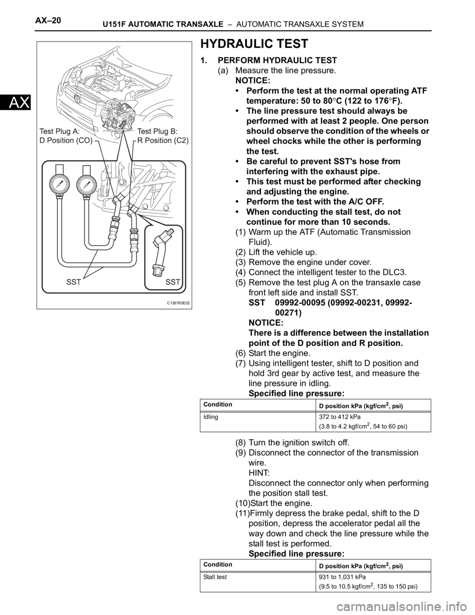
(5) Remove the test plug A on the transaxle case
front left side and install SST.
SST 09992-00095 (09992-00231, 09992-
00271)
NOTICE:
There is a difference between the installation
point of the D position and R position.
(6) Start the engine.
(7) Using intelligent tester, shift to D position and
hold 3rd gear by active test, and measure the
line pressure in idling.
Specified line pressure:
(8) Turn the ignition switch off.
(9) Disconnect the connector of the transmission
wire.
HINT:
Disconnect the connector only when performing
the position stall test.
(10)Start the engine.
(11)Firmly depress the brake pedal, shift to the D
position, depress the accelerator pedal all the
way down and check the line pressure while the
stall test is performed.
Specified line pressure:
C136760E02
Condition
D position kPa (kgf/cm2, psi)
Idling 372 to 412 kPa
(3.8 to 4.2 kgf/cm
2, 54 to 60 psi)
Condition
D position kPa (kgf/cm
2, psi)
Stall test 931 to 1,031 kPa
(9.5 to 10.5 kgf/cm
2, 135 to 150 psi)
Page 1140 of 2000

U151F AUTOMATIC TRANSAXLE – AUTOMATIC TRANSAXLE SYSTEMAX–21
AX
(12)Turn the ignition switch off.
(13)Remove SST, and install the test plug A.
(14)Remove the test plug B, install SST and start
the engine.
SST 09992-00095 (09992-00231, 09992-
00271)
(15)Connect the transmission wire connector,
depress the brake pedal firmly, shift to the R
position and check the line pressure while the
engine is idling and during the stall test.
Specified line pressure:
(16)Remove SST, and install the test plug B.
(17)Clear the DTC.
Evaluation:
Condition
R position kPa (kgf/cm2, psi)
Idling 672 to 742 kPa
(6.9 to 7.6 kgf/cm
2, 97 to 108 psi)
Stall test 1,768 to 1,968 kPa
(18.0 to 20.0 kgf/cm
2, 256 to 285 psi)
Problem Possible cause
Measured values at all positions are higher than specified • Shift solenoid valve SLT defective
• Regulator valve defective
Measured values at all positions are lower than specified • Shift solenoid valve SLT defective
• Regulator valve defective
• Oil pump defective
• U/D (underdrive) direct clutch defective
Pressure is low when shift lever is on D only • D position circuit fluid leak
• Forward clutch defective
Pressure is low when shift lever is on R only • R position circuit fluid leak
• Reverse clutch defective
• 1st and reverse brake defective
Page 1142 of 2000

U151F AUTOMATIC TRANSAXLE – AUTOMATIC TRANSAXLE SYSTEMAX–23
AX
INITIALIZATION
1. RESET MEMORY
NOTICE:
• Perform the RESET MEMORY procedures (A/T
initialization) when replacing the automatic
transaxle assembly, engine assembly or ECM.
• RESET MEMORY can be performed only with the
intelligent tester.
HINT:
The ECM memorizes the vehicle conditions when the
ECT controls the automatic transaxle assembly and
engine assembly. Therefore, when the automatic
transaxle assembly, engine assembly, or ECM has been
replaced, it is necessary to reset the memory so that the
ECM can memorize the new information.
The reset procedures are as follows.
(a) Turn the ignition switch OFF.
(b) Connect the intelligent tester to the CAN VIM. Then
connect the CAN VIM to the DLC3.
(c) Turn the ignition switch ON and turn the tester ON.
(d) Enter the following menus: DIAGNOSIS /
ENHANCED OBD II.
(e) Perform the reset memory procedures from the
Engine menu.
CAUTION:
After performing the RESET MEMORY
procedures, be sure to perform the ROAD TEST
(see page AX-13) as described earlier.
HINT:
The ECM learns through the ROAD TEST.
Page 1149 of 2000
AX–30U151F AUTOMATIC TRANSAXLE – AUTOMATIC TRANSAXLE SYSTEM
AX
TERMINALS OF ECM
1. CHECK ECM
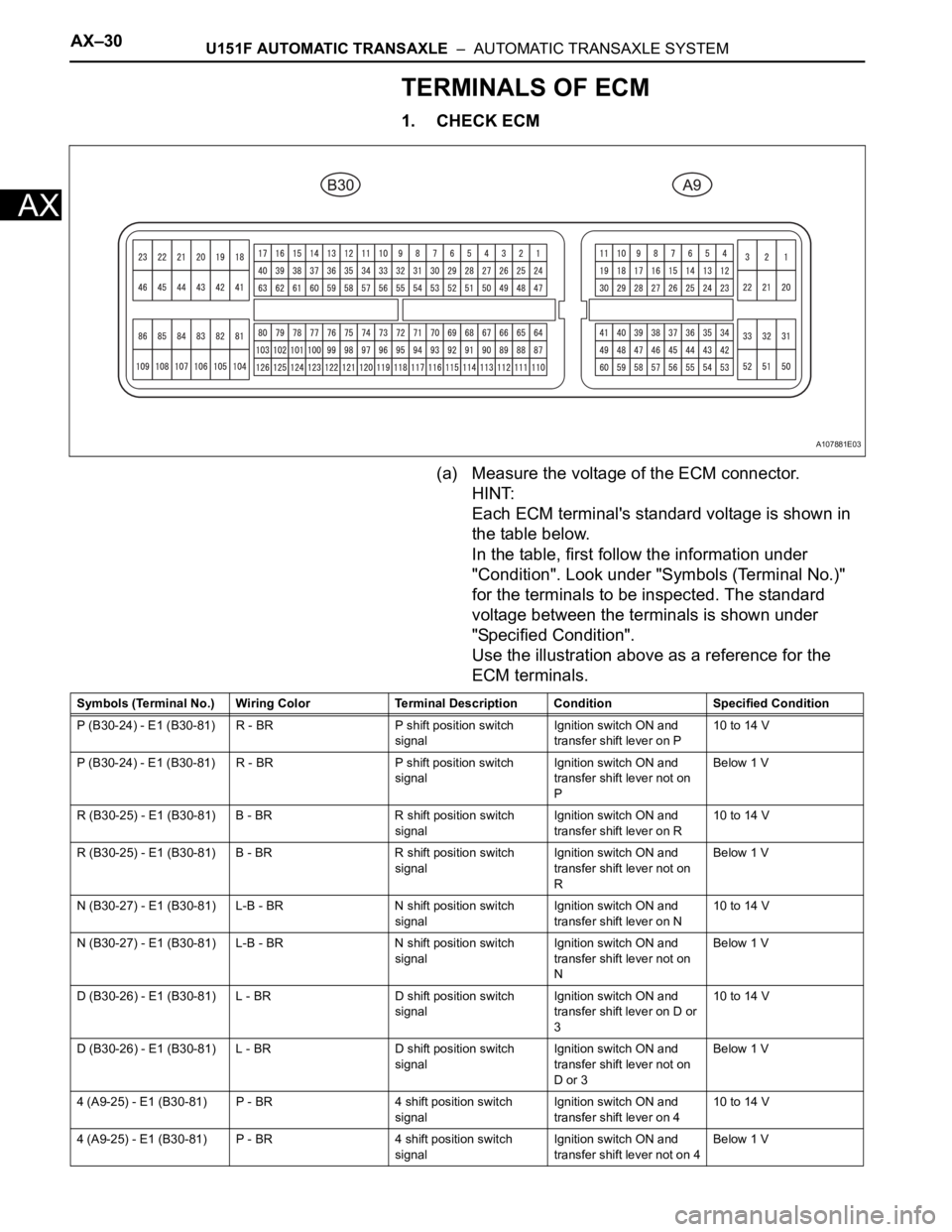
(a) Measure the voltage of the ECM connector.
HINT:
Each ECM terminal's standard voltage is shown in
the table below.
In the table, first follow the information under
"Condition". Look under "Symbols (Terminal No.)"
for the terminals to be inspected. The standard
voltage between the terminals is shown under
"Specified Condition".
Use the illustration above as a reference for the
ECM terminals.
A107881E03
Symbols (Terminal No.) Wiring Color Terminal Description ConditionSpecified Condition
P (B30-24) - E1 (B30-81) R - BR P shift position switch
signalIgnition switch ON and
transfer shift lever on P10 to 14 V
P (B30-24) - E1 (B30-81) R - BR P shift position switch
signalIgnition switch ON and
transfer shift lever not on
PBelow 1 V
R (B30-25) - E1 (B30-81) B - BR R shift position switch
signalIgnition switch ON and
transfer shift lever on R10 to 14 V
R (B30-25) - E1 (B30-81) B - BR R shift position switch
signalIgnition switch ON and
transfer shift lever not on
RBelow 1 V
N (B30-27) - E1 (B30-81) L-B - BR N shift position switch
signalIgnition switch ON and
transfer shift lever on N10 to 14 V
N (B30-27) - E1 (B30-81) L-B - BR N shift position switch
signalIgnition switch ON and
transfer shift lever not on
NBelow 1 V
D (B30-26) - E1 (B30-81) L - BR D shift position switch
signalIgnition switch ON and
transfer shift lever on D or
310 to 14 V
D (B30-26) - E1 (B30-81) L - BR D shift position switch
signalIgnition switch ON and
transfer shift lever not on
D or 3Below 1 V
4 (A9-25) - E1 (B30-81) P - BR 4 shift position switch
signalIgnition switch ON and
transfer shift lever on 410 to 14 V
4 (A9-25) - E1 (B30-81) P - BR 4 shift position switch
signalIgnition switch ON and
transfer shift lever not on 4Below 1 V
Page 1150 of 2000

U151F AUTOMATIC TRANSAXLE – AUTOMATIC TRANSAXLE SYSTEMAX–31
AX
3 (B30-29) - E1 (B30-81) LG - BR 3 shift position switch
signalIgnition switch ON and
transfer shift lever on 310 to 14 V
3 (B30-29) - E1 (B30-81) LG - BR 3 shift position switch
signalIgnition switch ON and
transfer shift lever not on 3Below 1 V
2 (B30-28) - E1 (B30-81) V - BR 2 shift position switch
signalIgnition switch ON and
transfer shift lever on 2
and L10 to 14 V
2 (B30-28) - E1 (B30-81) V - BR 2 shift position switch
signalIgnition switch ON and
transfer shift lever not on 2
and LBelow 1 V
L (A9-26) - E1 (B30-81) V - BR L shift position switch
signalIgnition switch ON and
transfer shift lever on L10 to 14 V
L (A9-26) - E1 (B30-81) V - BR L shift position switch
signalIgnition switch ON and
transfer shift lever not on LBelow 1 V
STP (A9-36) - E1 (B30-81) L - BR Stop light switch signal Brake pedal is depressed Between 10 V and 14 V
STP (A9-36) - E1 (B30-81) L - BR Stop light switch signal Brake pedal is released Below 1 V
SL1+ (B30-16) - SL1-
(B30-17)P - LG SL1 solenoid signal Engine idle speed Pulse generation
(see waveform 1)
SL1+ (B30-16) - SL1-
(B30-17)P - LG SL1 solenoid signal Ignition switch ON Pulse generation
(see waveform 1)
SL1+ (B30-16) - SL1-
(B30-17)P - LG SL1 solenoid signal 1st gear Pulse generation
(see waveform 1)
SL1+ (B30-16) - SL1-
(B30-17)P - LG SL1 solenoid signal Not on 1st gear Below 1 V
SL2+ (B30-12) - SL2-
(B30-13)BR - R SL2 solenoid signal Engine idle speed Pulse generation
(see waveform 2)
SL2+ (B30-12) - SL2-
(B30-13)BR - R SL2 solenoid signal Ignition switch ON Pulse generation
(see waveform 2)
SL2+ (B30-12) - SL2-
(B30-13)BR - R SL2 solenoid signal 1st or 2nd gear Pulse generation
(see waveform 2)
SL2+ (B30-12) - SL2-
(B30-13)BR - R SL2 solenoid signal 3rd, 4th or 5th gear Below 1 V
SL3+ (B30-14) - SL3-
(B30-15)GR - G-R SL3 solenoid signal Engine idle speed Pulse generation
(see waveform 3)
SL3+ (B30-14) - SL3-
(B30-15)GR - G-R SL3 solenoid signal Ignition switch ON Pulse generation
(see waveform 3)
SL3+ (B30-14) - SL3-
(B30-15)GR - G-R SL3 solenoid signal 1st or 2nd gear Pulse generation
(see waveform 3)
SL3+ (B30-14) - SL3-
(B30-15)GR - G-R SL3 solenoid signal 3rd, 4th or 5th gear Below 1 V
DSL (B30-9) - E01 (B30-
22)V - BR DSL solenoid signal Vehicle speed 65 km/h (40
mph), lock-up (ON to OFF)Below 1 V
DSL (B30-9) - E01 (B30-
22)V - BR DSL solenoid signal Vehicle driving under lock-
up positionPulse generation
(see waveform 4)
SLT+ (B30-11) - SLT-
(B30-10)L - W SLT solenoid signal Engine idle speed Pulse generation
(see waveform 5)
SR (B30-8) - E01 (B30-22) G - BR SR solenoid signal Ignition switch ON Below 1 V
SR (B30-8) - E01 (B30-22) G - BR SR solenoid signal 3th, 4th or 5th gear 10 to 14 V
SR (B30-8) - E01 (B30-22) G - BR SR solenoid signal 1st or 2nd gear Below 1 V
S4 (B30-7) - E01 (B30-22) L-B - BR S4 solenoid signal Ignition switch ON Below 1 V
S4 (B30-7) - E01 (B30-22) L-B - BR S4 solenoid signal 5th gear 10 to 14 V
S4 (B30-7) - E01 (B30-22) L-B - BR S4 solenoid signal Not on 5th gear Below 1 V
THO1 (B30-126) - ETHO
(B30-124)Y - B ATF temperature sensor
signalATF temperature 115
C
(239
F) or moreBelow 1.5 V
NT+ (B30-6) - NT- (B30-5) B - G Speed sensor (NT) signal Vehicle speed 20 km/h (12
mph)Pulse generation
(see waveform 6) Symbols (Terminal No.) Wiring Color Terminal Description ConditionSpecified Condition
Page 1153 of 2000
AX–34U151F AUTOMATIC TRANSAXLE – AUTOMATIC TRANSAXLE SYSTEM
AX
DIAGNOSIS SYSTEM
1. DESCRIPTION
(a) When troubleshooting On-Board Diagnostic (OBD
II) vehicles, the vehicle must be connected to the
OBD II scan tool (complying with SAE J1987).
Various data output from the vehicle's ECM can
then be read.
(b) OBD II regulations require that the vehicle's on-
board computer illuminates the Malfunction
Indicator Lamp (MIL) on the instrument panel when
the computer detects a malfunction in:
(1) The emission control system/components
(2) The powertrain control components (which affect
vehicle emissions)
(3) The computer
In addition, the applicable Diagnostic Trouble
Codes (DTCs) prescribed by SAE J2012 are
recorded in the ECM memory.
When the malfunction does not reoccur, the MIL
stays illuminated until the ignition switch is
turned OFF, and the MIL turns OFF when the
engine is started. However, the DTCs remain
recorded in the ECM memory.
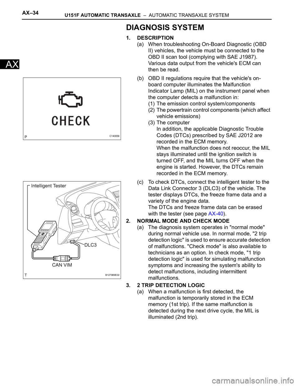
(c) To check DTCs, connect the intelligent tester to the
Data Link Connector 3 (DLC3) of the vehicle. The
tester displays DTCs, the freeze frame data and a
variety of the engine data.
The DTCs and freeze frame data can be erased
with the tester (see page AX-40).
2. NORMAL MODE AND CHECK MODE
(a) The diagnosis system operates in "normal mode"
during normal vehicle use. In normal mode, "2 trip
detection logic" is used to ensure accurate detection
of malfunctions. "Check mode" is also available to
technicians as an option. In check mode, "1 trip
detection logic" is used for simulating malfunction
symptoms and increasing the system's ability to
detect malfunctions, including intermittent
malfunctions.
3. 2 TRIP DETECTION LOGIC
(a) When a malfunction is first detected, the
malfunction is temporarily stored in the ECM
memory (1st trip). If the same malfunction is
detected during the next drive cycle, the MIL is
illuminated (2nd trip).
C140856
B127989E02
Page 1154 of 2000
U151F AUTOMATIC TRANSAXLE – AUTOMATIC TRANSAXLE SYSTEMAX–35
AX
4. FREEZE FRAME DATA
(a) Freeze frame data records the engine conditions
(fuel system, calculated load, engine coolant
temperature, fuel trim, engine speed, vehicle speed,
etc.) when a malfunction is detected. When
troubleshooting, freeze frame data can help
determine if the vehicle was running or stopped, if
the engine was warmed up or not, if the air-fuel ratio
was lean or rich, and other data from the time the
malfunction occurred.
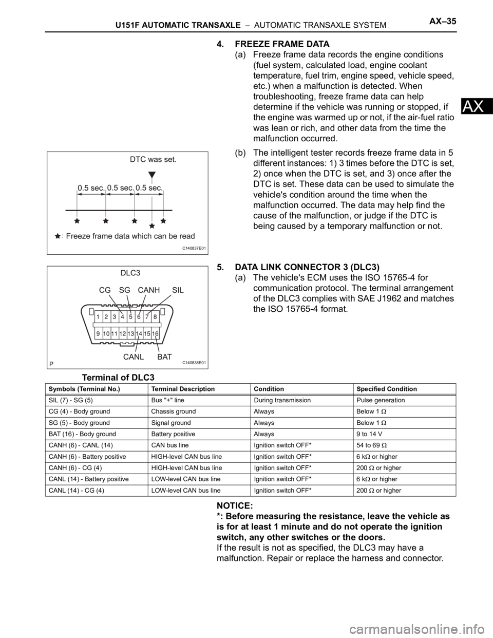
(b) The intelligent tester records freeze frame data in 5
different instances: 1) 3 times before the DTC is set,
2) once when the DTC is set, and 3) once after the
DTC is set. These data can be used to simulate the
vehicle's condition around the time when the
malfunction occurred. The data may help find the
cause of the malfunction, or judge if the DTC is
being caused by a temporary malfunction or not.
5. DATA LINK CONNECTOR 3 (DLC3)
(a) The vehicle's ECM uses the ISO 15765-4 for
communication protocol. The terminal arrangement
of the DLC3 complies with SAE J1962 and matches
the ISO 15765-4 format.
Terminal of DLC3
NOTICE:
*: Before measuring the resistance, leave the vehicle as
is for at least 1 minute and do not operate the ignition
switch, any other switches or the doors.
If the result is not as specified, the DLC3 may have a
malfunction. Repair or replace the harness and connector.
C140837E01
C140838E01
Symbols (Terminal No.) Terminal Description Condition Specified Condition
SIL (7) - SG (5) Bus "+" line During transmission Pulse generation
CG (4) - Body ground Chassis ground Always Below 1
SG (5) - Body ground Signal ground Always Below 1
BAT (16) - Body ground Battery positive Always 9 to 14 V
CANH (6) - CANL (14) CAN bus line Ignition switch OFF* 54 to 69
CANH (6) - Battery positive HIGH-level CAN bus line Ignition switch OFF* 6 k or higher
CANH (6) - CG (4) HIGH-level CAN bus line Ignition switch OFF* 200
or higher
CANL (14) - Battery positive LOW-level CAN bus line Ignition switch OFF* 6 k
or higher
CANL (14) - CG (4) LOW-level CAN bus line Ignition switch OFF* 200
or higher