Page 896 of 2000

IG–62GR-FE IGNITION – IGNITION SYSTEM
IG
(c) Perform troubleshooting using the spark test
flowchart.
(1) Check that the ignition coil connector is
securely connected.
Result
(2) Perform the spark test on each ignition coil.
1. Replace the ignition coil with a normal one.
2. Perform the spark test again.
Result
(3) Check the power supply to the ignition coil.
1. Disconnect the ignition coil connector.
2. Turn the ignition switch ON.
3. Measure the voltage of the wire harness
side connector.
Standard voltage
Result
(4) Check the resistance of the crankshaft position
sensor.
Standard resistance
Result
(5) Check the IGT signal from the ECM.
Result
Result Proceed to
NG Connect securely
OK Go to next step
Result Proceed to
OK Replace ignition coil
NG Go to next step
A136824
Tester Connection Specified Condition
1 (+B) - 4 (GND) 9 to 14 V
Result Proceed to
NG Check wire harness and connector
OK Go to next step
Temperature Condition Specified Condition
Cold 1,630 to 2,740
Hot 2,065 to 3,225
Result Proceed to
NG Replace crankshaft position sensor
OK Go to next step
Result Proceed to
NG Check ECM (see page ES-220)
OK Repair wiring between ignition coil and
ECM
Page 897 of 2000

2GR-FE IGNITION – IGNITION SYSTEMIG–7
IG
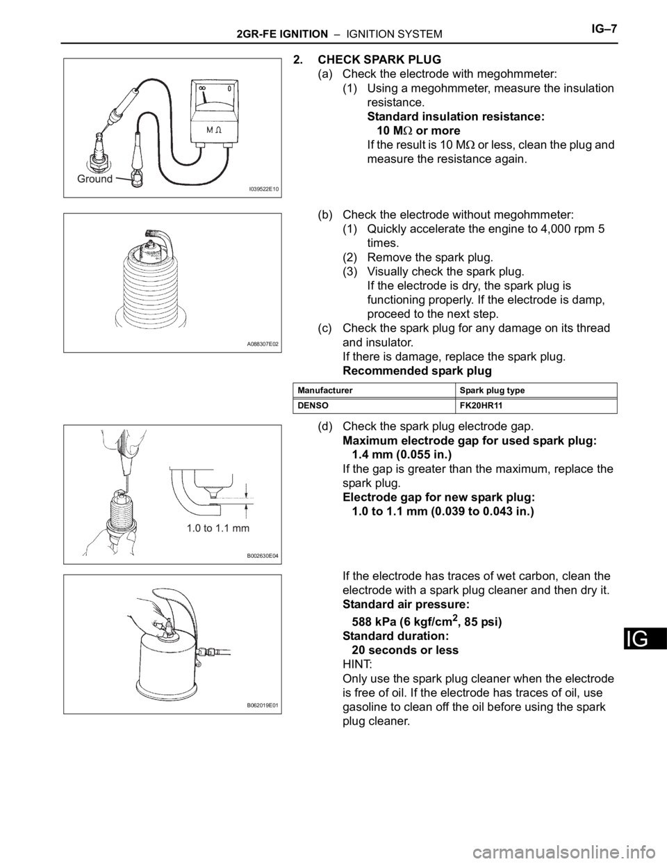
2. CHECK SPARK PLUG
(a) Check the electrode with megohmmeter:
(1) Using a megohmmeter, measure the insulation
resistance.
Standard insulation resistance:
10 M
or more
If the result is 10 M
or less, clean the plug and
measure the resistance again.
(b) Check the electrode without megohmmeter:
(1) Quickly accelerate the engine to 4,000 rpm 5
times.
(2) Remove the spark plug.
(3) Visually check the spark plug.
If the electrode is dry, the spark plug is
functioning properly. If the electrode is damp,
proceed to the next step.
(c) Check the spark plug for any damage on its thread
and insulator.
If there is damage, replace the spark plug.
Recommended spark plug
(d) Check the spark plug electrode gap.
Maximum electrode gap for used spark plug:
1.4 mm (0.055 in.)
If the gap is greater than the maximum, replace the
spark plug.
Electrode gap for new spark plug:
1.0 to 1.1 mm (0.039 to 0.043 in.)
If the electrode has traces of wet carbon, clean the
electrode with a spark plug cleaner and then dry it.
Standard air pressure:
588 kPa (6 kgf/cm
2, 85 psi)
Standard duration:
20 seconds or less
HINT:
Only use the spark plug cleaner when the electrode
is free of oil. If the electrode has traces of oil, use
gasoline to clean off the oil before using the spark
plug cleaner.
I039522E10
A088307E02
Manufacturer Spark plug type
DENSO FK20HR11
B002630E04
B062019E01
Page 908 of 2000
2AZ-FE STARTING – IGNITION SWITCHST–19
ST
If the result is not as specified, replace the switch
assembly.
INSTALLATION
1. INSTALL IGNITION SWITCH ASSEMBLY
(a) Install the ignition switch with the 2 screws.
(b) Install the ignition key cylinder light connector.
(c) Install the ignition switch connector.
2. INSTALL STEERING COLUMN COVER LOWER
(a) Attach the 4 claws to install the steering column
lower cover.
3. CONNECT CABLE TO NEGATIVE BATTERY
TERMINAL
A124915
A124916
A134309
Page 919 of 2000
2GR-FE STARTING – IGNITION SWITCHST–19
ST
INSTALLATION
1. INSTALL IGNITION SWITCH ASSEMBLY
(a) Install the ignition switch with the 2 screws.
(b) Connect the ignition key cylinder light connector.
(c) Connect the ignition switch connector.
2. INSTALL STEERING COLUMN COVER LOWER
(a) Install the steering column cover lower (see page
SR-20).
3. CONNECT CABLE TO NEGATIVE BATTERY
TERMINAL
A124915
A124916
Page 929 of 2000

CH–62GR-FE CHARGING – CHARGING SYSTEM
CH
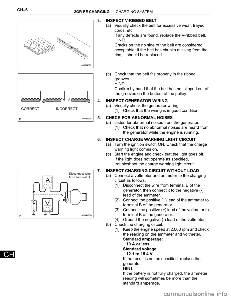
3. INSPECT V-RIBBED BELT
(a) Visually check the belt for excessive wear, frayed
cords, etc.
If any defects are found, replace the V-ribbed belt.
HINT:
Cracks on the rib side of the belt are considered
acceptable. If the belt has chunks missing from the
ribs, it should be replaced.
(b) Check that the belt fits properly in the ribbed
grooves.
HINT:
Confirm by hand that the belt has not slipped out of
the grooves on the bottom of the pulley.
4. INSPECT GENERATOR WIRING
(a) Visually check the generator wiring.
(1) Check that the wiring is in good condition.
5. CHECK FOR ABNORMAL NOISES
(a) Listen for abnormal noises from the generator.
(1) Check that no abnormal noises are heard from
the generator while the engine is running.
6. INSPECT CHARGE WARNING LIGHT CIRCUIT
(a) Turn the ignition switch ON. Check that the charge
warning light comes on.
(b) Start the engine and check that the light goes off.
If the light does not operate as specified,
troubleshoot the charge warning light circuit.
7. INSPECT CHARGING CIRCUIT WITHOUT LOAD
(a) Connect a voltmeter and ammeter to the charging
circuit as follows.
(1) Disconnect the wire from terminal B of the
generator, then connect it to the negative (-)
lead of the ammeter.
(2) Connect the positive (+) lead of the ammeter to
terminal B of the generator.
(3) Connect the positive (+) lead of the voltmeter to
terminal B of the generator.
(4) Ground the negative (-) lead of the voltmeter.
(b) Check the charging circuit.
(1) Keep the engine speed at 2,000 rpm and check
the reading on the ammeter and voltmeter.
Standard amperage:
10 A or less
Standard voltage:
12.1 to 15.4 V
If the result is not as specified, replace the
generator.
HINT:
If the battery is not fully charged, the ammeter
reading will sometimes be more than the
standard amperage.
A095340E01
A111819E01
A088419E04
Page 956 of 2000

AX–22U140F AUTOMATIC TRANSAXLE – AUTOMATIC TRANSAXLE SYSTEM
AX
INITIALIZATION
1. RESET MEMORY
NOTICE:
• Perform the RESET MEMORY procedures (A/T
initialization) when replacing the automatic
transaxle assembly, engine assembly or ECM.
• RESET MEMORY can be performed only with the
intelligent tester.
HINT:
The ECM memorizes the vehicle conditions when the
ECT controls the automatic transaxle assembly and
engine assembly. Therefore, when the automatic
transaxle assembly, engine assembly, or ECM has been
replaced, it is necessary to reset the memory so that the
ECM can memorize the new information.
The reset procedures are as follows.
(a) Turn the ignition switch OFF.
(b) Connect the intelligent tester to the CAN VIM. Then
connect the CAN VIM to the DLC3.
(c) Turn the ignition switch ON and turn the tester ON.
(d) Enter the following menus: DIAGNOSIS /
ENHANCED OBD II.
(e) Perform the reset memory procedures from the
Engine menu.
CAUTION:
After performing the RESET MEMORY
procedures, be sure to perform the ROAD TEST
(see page AX-12) as described earlier.
HINT:
The ECM learns through the ROAD TEST.
Page 963 of 2000

U140F AUTOMATIC TRANSAXLE – AUTOMATIC TRANSAXLE SYSTEMAX–29
AX
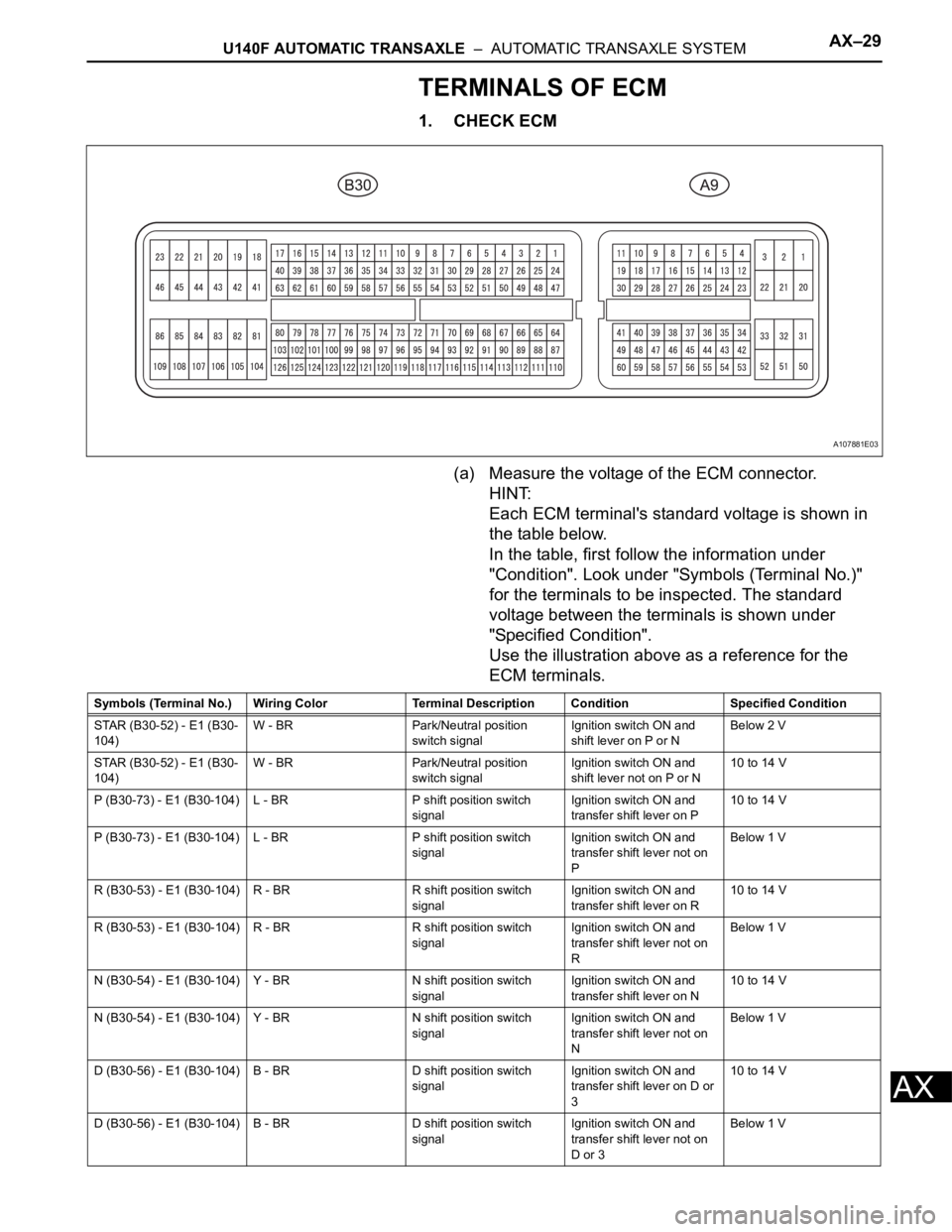
TERMINALS OF ECM
1. CHECK ECM
(a) Measure the voltage of the ECM connector.
HINT:
Each ECM terminal's standard voltage is shown in
the table below.
In the table, first follow the information under
"Condition". Look under "Symbols (Terminal No.)"
for the terminals to be inspected. The standard
voltage between the terminals is shown under
"Specified Condition".
Use the illustration above as a reference for the
ECM terminals.
A107881E03
Symbols (Terminal No.) Wiring Color Terminal Description ConditionSpecified Condition
STAR (B30-52) - E1 (B30-
104)W - BR Park/Neutral position
switch signalIgnition switch ON and
shift lever on P or NBelow 2 V
STAR (B30-52) - E1 (B30-
104)W - BR Park/Neutral position
switch signalIgnition switch ON and
shift lever not on P or N10 to 14 V
P (B30-73) - E1 (B30-104) L - BR P shift position switch
signalIgnition switch ON and
transfer shift lever on P10 to 14 V
P (B30-73) - E1 (B30-104) L - BR P shift position switch
signalIgnition switch ON and
transfer shift lever not on
PBelow 1 V
R (B30-53) - E1 (B30-104) R - BR R shift position switch
signalIgnition switch ON and
transfer shift lever on R10 to 14 V
R (B30-53) - E1 (B30-104) R - BR R shift position switch
signalIgnition switch ON and
transfer shift lever not on
RBelow 1 V
N (B30-54) - E1 (B30-104) Y - BR N shift position switch
signalIgnition switch ON and
transfer shift lever on N10 to 14 V
N (B30-54) - E1 (B30-104) Y - BR N shift position switch
signalIgnition switch ON and
transfer shift lever not on
NBelow 1 V
D (B30-56) - E1 (B30-104) B - BR D shift position switch
signalIgnition switch ON and
transfer shift lever on D or
310 to 14 V
D (B30-56) - E1 (B30-104) B - BR D shift position switch
signalIgnition switch ON and
transfer shift lever not on
D or 3Below 1 V
Page 964 of 2000

AX–30U140F AUTOMATIC TRANSAXLE – AUTOMATIC TRANSAXLE SYSTEM
AX
3 (A9-26) - E1 (B30-104) P - BR 3 shift position switch
signalIgnition switch ON and
transfer shift lever on 310 to 14 V
3 (A9-26) - E1 (B30-104) P - BR 3 shift position switch
signalIgnition switch ON and
transfer shift lever not on 3Below 1 V
2 (B30-55) - E1 (B30-104) P - BR 2 shift position switch
signalIgnition switch ON and
transfer shift lever on 2
and L10 to 14 V
2 (B30-55) - E1 (B30-104) P - BR 2 shift position switch
signalIgnition switch ON and
transfer shift lever not on 2
and LBelow 1 V
L (B30-74) - E1 (B30-104) LG - BR L shift position switch
signalIgnition switch ON and
transfer shift lever on L10 to 14 V
L (B30-74) - E1 (B30-104) LG - BR L shift position switch
signalIgnition switch ON and
transfer shift lever not on LBelow 1 V
STP (A9-36) - E1 (B30-
104)L - BR Stop light switch signal Brake pedal is depressed Between 10 V and 14 V
STP (A9-36) - E1 (B30-
104)L - BR Stop light switch signal Brake pedal is released Below 1 V
SL1+ (B30-57) - SL1-
(B30-77)V - P SL1 solenoid signal Engine idle speed Pulse generation
(see waveform 1)
SL1+ (B30-57) - SL1-
(B30-77)V - P SL1 solenoid signal Ignition switch ON Pulse generation
(see waveform 1)
SL1+ (B30-57) - SL1-
(B30-77)V - P SL1 solenoid signal 1st gear Pulse generation
(see waveform 1)
SL1+ (B30-57) - SL1-
(B30-77)V - P SL1 solenoid signal Not on 1st gear Below 1 V
SL2+ (B30-58) - SL2-
(B30-59)Y - L SL2 solenoid signal Engine idle speed Pulse generation
(see waveform 2)
SL2+ (B30-58) - SL2-
(B30-59)Y - L SL2 solenoid signal Ignition switch ON Pulse generation
(see waveform 2)
SL2+ (B30-58) - SL2-
(B30-59)Y - L SL2 solenoid signal 1st or 2nd gear Pulse generation
(see waveform 2)
SL2+ (B30-58) - SL2-
(B30-59)Y - L SL2 solenoid signal 3rd or O/D gear Below 1 V
DSL (B30-79) - E01 (B30-
45)G - BR DSL solenoid signal Vehicle speed 65 km/h (40
mph), lock-up (ON to OFF)Below 1 V
DSL (B30-79) - E01 (B30-
45)G - BR DSL solenoid signal Vehicle driving under lock-
up positionPulse generation
(see waveform 3)
SLT+ (B30-76) - SLT-
(B30-75)R - GR SLT solenoid signal Engine idle speed Pulse generation
(see waveform 4)
S4 (B30-78) - E01 (B30-
45)W - BR S4 solenoid signal Ignition switch ON Below 1 V
S4 (B30-78) - E01 (B30-
45)W - BR S4 solenoid signal O/D gear 10 to 14 V
S4 (B30-78) - E01 (B30-
45)W - BR S4 solenoid signal Not on O/D gear Below 1 V
THO1 (B30-72) - ETHO
(B30-95)LG- BR ATF temperature sensor
signalATF temperature: 115
C
(239F) or moreBelow 1.5 V
NT+ (B30-125) - NT- (B30-
124)W - R Speed sensor (NT) signal Vehicle speed 20 km/h (12
mph)Pulse generation
(see waveform 5)
NC+ (B30-101) - NC-
(B30-102)R - W Speed sensor (NC) signal Vehicle speed 30 km/h (19
mph): (3rd gear)
Engine speed 1,400 rpmPulse generation
(see waveform 6) Symbols (Terminal No.) Wiring Color Terminal Description ConditionSpecified Condition