2006 TOYOTA RAV4 ignition
[x] Cancel search: ignitionPage 568 of 2000

ES–442GR-FE ENGINE CONTROL SYSTEM – SFI SYSTEM
ES
If communication is normal: Inspect the DLC3 on the
original vehicle.
If communication is still not possible: The problem is
probably in the tester itself. Consult the Service
Department listed in the instruction manual.
6. BATTERY VOLTAGE
Standard battery voltage:
11 to 14 V
If the voltage is below 11 V, replace or recharge the
battery before proceeding.
7. MIL (Malfunction Indicator Lamp)
(a) The MIL is illuminated when the ignition switch is
first turned ON (the engine is not running).
(b) The MIL should turn OFF when the engine is
started. If the MIL remains illuminated, the diagnosis
system has detected a malfunction or abnormality in
the system.
HINT:
If the MIL is not illuminated when the ignition switch
is first turned ON, check the MIL circuit (see page
ES-430).
8. ALL READINESS
For the vehicle, using the intelligent tester allows
readiness codes corresponding to all DTCs to be read.
When diagnosis (normal or malfunctioning) has been
complete, readiness codes are set. Select the following
menu items on the intelligent tester: ENHANCED OBD II
/ MONITOR STATUS.
Page 569 of 2000

2GR-FE ENGINE CONTROL SYSTEM – SFI SYSTEMES–45
ES
DTC CHECK / CLEAR
NOTICE:
When the diagnosis system is changed from normal
mode to check mode or vice versa, all DTCs and freeze
frame data recorded in normal mode are erased. Before
changing modes, always check and make a note of any
DTCs and freeze frame data.
HINT:
• DTCs which are stored in the ECM can be displayed on
the intelligent tester. The intelligent tester can display
current and pending DTCs.
• Some DTCs are not set if the ECM does not detect the
same malfunction again during a second consecutive
driving cycle. However, such malfunctions, detected on
only one occasion, are stored as pending DTCs.
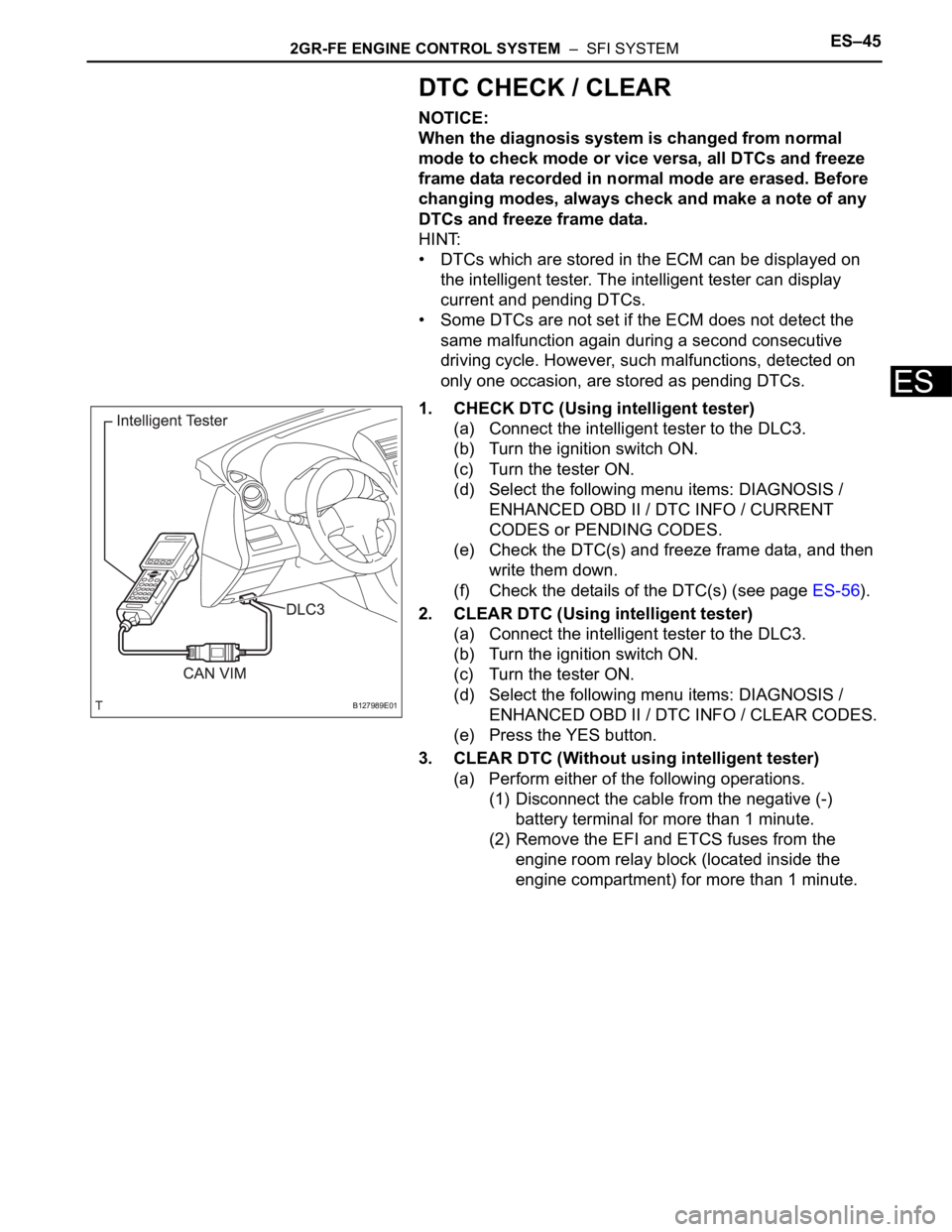
1. CHECK DTC (Using intelligent tester)
(a) Connect the intelligent tester to the DLC3.
(b) Turn the ignition switch ON.
(c) Turn the tester ON.
(d) Select the following menu items: DIAGNOSIS /
ENHANCED OBD II / DTC INFO / CURRENT
CODES or PENDING CODES.
(e) Check the DTC(s) and freeze frame data, and then
write them down.
(f) Check the details of the DTC(s) (see page ES-56).
2. CLEAR DTC (Using intelligent tester)
(a) Connect the intelligent tester to the DLC3.
(b) Turn the ignition switch ON.
(c) Turn the tester ON.
(d) Select the following menu items: DIAGNOSIS /
ENHANCED OBD II / DTC INFO / CLEAR CODES.
(e) Press the YES button.
3. CLEAR DTC (Without using intelligent tester)
(a) Perform either of the following operations.
(1) Disconnect the cable from the negative (-)
battery terminal for more than 1 minute.
(2) Remove the EFI and ETCS fuses from the
engine room relay block (located inside the
engine compartment) for more than 1 minute.
B127989E01
Page 570 of 2000

ES–462GR-FE ENGINE CONTROL SYSTEM – SFI SYSTEM
ES
FREEZE FRAME DATA
1. DESCRIPTION
Freeze frame data records the engine conditions (fuel
system, calculated load, engine coolant temperature,
fuel trim, engine speed, vehicle speed, etc.) when a
malfunction is detected. When troubleshooting, it can
help determine if the vehicle was running or stopped, the
engine was warmed up or not, the air-fuel ratio was Lean
or Rich, and other data from the time the malfunction
occurred.
HINT:
If it is impossible to duplicate the problem even though a
DTC is detected, confirm the freeze frame data.
The ECM records engine conditions in the form of freeze
frame data every 0.5 seconds. Using the intelligent
tester, 5 separate sets of freeze frame data can be
checked.
– 3 data sets before the DTC was set.
– 1 data set when the DTC was set.
– 1 data set after the DTC was set.
These data sets can be used to simulate the condition
of the vehicle around the time of the occurrence of the
malfunction. The data may assist in identifying the
cause of the malfunction, and in judging whether it
was temporary or not.
2. LIST OF FREEZE FRAME DATA
A103809E11
LABEL
(Intelligent Tester Display)Measurement Item Diagnostic Note
INJECTOR Injection period of No. 1 cylinder -
IGN ADVANCE Ignition advance -
CALC LOAD Calculated load Calculated load by ECM
VEHICLE LOAD Vehicle load -
MAF Mass air flow volumeIf approximately 0.0 g/sec.:
• Mass air flow meter power source circuit
open or short
• VG circuit open or short
If 160.0 g/sec. or more:
• E2G circuit open
ENGINE SPD Engine speed -
VEHICLE SPD Vehicle speed Speed indicated on speedometer
COOLANT TEMP Engine coolant temperatureIf -40
C (-40F), sensor circuit open
If 140
C (284F) or more, sensor circuit
shorted
INTAKE AIR Intake air temperature If -40
C (-40F), sensor circuit open
If 140
C (284F) or more, sensor circuit
shorted
AIR-FUEL RATIO Ratio compared to stoichiometric level -
PURGE DENSITY Learning value of purge density -
EVAP PURGE FLOWRatio of evaporative purge flow to intake air
volume-
EVAP PURGE VSV EVAP purge VSV duty ratio -
KNOCK CRRT VAL Correction learning value of knocking -
Page 571 of 2000

2GR-FE ENGINE CONTROL SYSTEM – SFI SYSTEMES–47
ES
KNOCK FB VAL Feedback value of knocking -
ACCEL POS #1Absolute Accelerator Pedal Position (APP)
No.1-
ACCEL POS #2 Absolute APP No. 2 -
THROTTLE POS Throttle sensor positioning -
THROTTLE POS Throttle position -
THROTTLE POS #2 Throttle sensor positioning #2 -
THROTTLE MOT Throttle motor -
O2S B1 S2
O2S B2 S2Heated oxygen sensor outputPerforming INJ VOL or A/F CONTROL
function of ACTIVE TEST enables technician
to check output voltage of sensor
AFS B1 S1
AFS B2 S1A/F sensor outputPerforming INJ VOL or A/F CONTROL
function of ACTIVE TEST enables technician
to check output voltage of sensor
TOTAL FT #1
TOTAL FT #2Total fuel trim -
SHORT FT #1
SHORT FT #2Short-term fuel trimShort-term fuel compensation used to
maintain air-fuel ratio at stoichiometric air-fuel
ratio
LONG FT #1
LONG FT #2Long-term fuel trimOverall fuel compensation carried out in long-
term to compensate a continual deviation of
short-term fuel trim from central valve
O2FT B1 S2
O2FT B2 S2Fuel trim at heated oxygen sensor -
AF FT B1 S1
AF FT B2 S1Fuel trim at A/F sensor-
AFS B1 S1
AFS B2 S1A/F sensor current-
CAT TEMP B1S1
CAT TEMP B2S1Estimated catalyst temperature (sensor 1)-
CAT TEMP B1S2
CAT TEMP B2S2Estimated catalyst temperature (sensor 2)-
S O2S B1S2
S O2S B2S2Sub heated oxygen sensor impedance
(sensor 2)-
INI COOL TEMP Engine coolant temperature at engine start -
INI INTAKE TEMP Intake air temperature at engine start -
INJ VOL Injection volume -
STARTER SIG Starter switch (STSW) signal -
PS SW Power steering signal -
PS SIGNAL Power steering signal (history)Signal status usually ON until ignition switch
turned OFF
CTP SW Closed throttle position switch -
A/C SIGNAL A/C signal -
PNP SW (NSW) Park/Neutral Position (PNP) switch signal -
ELECT LOAD SIG Electrical load signal -
STOP LIGHT SW Stop light switch -
BATTERY VOLTAGE Battery voltage -
ATM PRESSURE Atmosphere pressure -
FUEL PMP SP CTL Fuel pump speed control status -
ACIS VSVVSV for Acoustic Control Induction System
(ACIS)-
EVAP (Purge) VSV EVAP Purge VSV -
FUEL PUMP/SPD Fuel pump/speed status -LABEL
(Intelligent Tester Display)Measurement Item Diagnostic Note
Page 572 of 2000

ES–482GR-FE ENGINE CONTROL SYSTEM – SFI SYSTEM
ES
VVT CTRL B1
VVT CTRL B2VVT control status-
VA C U U M P U M PKey-off EVAP system leak detection pump
status(see page ES-369)
EVAP VENT VAL Key-off EVAP system vent valve status -
FAN MOTOR Electric fan motor -
AICV VSV VSV for Air Intake Control System (AICS) -
TC/TE1 TC and CG (TE1) terminals of DLC3 -
FC IDL Fuel cut idleON: when throttle valve fully closed and
engine speed over 3,500 rpm
FC TAU Fuel cut during very light loadFuel cut being performed under very light load
to prevent engine combustion from becoming
incomplete
IGNITION Ignition counter -
CYL #1 Cylinder #1 misfire Only displayed during idling
CYL #2 Cylinder #2 misfire Only displayed during idling
CYL #3 Cylinder #3 misfire Only displayed during idling
CYL #4 Cylinder #4 misfire Only displayed during idling
CYL #5 Cylinder #5 misfire Only displayed during idling
CYL #6 Cylinder #6 misfire Only displayed during idling
CYL ALL All cylinders misfire Only displayed during idling
MISFIRE RPM Engine speed when misfire occurred -
MISFIRE LOAD Engine load when misfire occurred -
MISFIRE MARGIN Margin to detect engine misfire -
ENG RUN TIME Accumulated engine running time -
TIME DTC CLEAR Cumulative time after DTC cleared -
DIST DTC CLEAR Accumulated distance from DTC cleared -
WU CYC DTC CLEAR Warm-up cycle after DTC cleared -LABEL
(Intelligent Tester Display)Measurement Item Diagnostic Note
Page 574 of 2000

SLIDING ROOF – SLIDING ROOF SYSTEMRF–3
RF
SYSTEM DESCRIPTION
1. GENERAL
This system has the following functions: manual slide
open and close; auto slide open and close; manual tilt up
and down; auto tilt up and down; jam protection; and key
off operation.
2. FUNCTION OF MAIN COMPONENT
3. SYSTEM OPERATION
The sliding roof has the following features.
Component Outline
Sliding roof drive gear sub-assembly (Sliding roof ECU) Sliding roof ECU controls sliding roof motor to rotate forward and
backward, which tilts or slides sliding roof glass
Overhead junction block Output of operation signals from built-in sliding roof switch to sliding
roof ECU are handled by overhead junction block
Function Outline
Manual slide open and close This function causes sliding roof to open (or close) when SLIDE
OPEN switch (or TILT UP switch) is pressed for a maximum of 0.3
seconds. Sliding roof stops as soon as switch is released.
Auto slide open and close This function causes sliding roof to be fully opened (or closed) when
SLIDE OPEN switch (or TILT UP switch) is pressed for a minimum of
0.3 seconds
Manual tilt up and down This function causes sliding roof to tilt up (or tilt down) when TILT UP
switch (or SLIDE OPEN switch) is pressed for a maximum of 0.3
seconds
Auto tilt up and down This function enables sliding roof to tilt up (or down) when TILT UP
switch (or SLIDE OPEN switch) is pressed for a minimum of 0.3
seconds.
Jam protection function The jam protection function automatically stops sliding roof, or stops
sliding roof and makes it open halfway (or fully tilts it upward) if a
foreign object gets jammed in sliding roof during auto close operation
(or auto tilt down operation).
Key off operation Key off operation function makes it possible to operate sliding roof for
approximately 45 seconds after ignition switch is turned off if front
doors are not opened
Page 580 of 2000

2AZ-FE ENGINE MECHANICAL – TIMING CHAINEM–23
EM
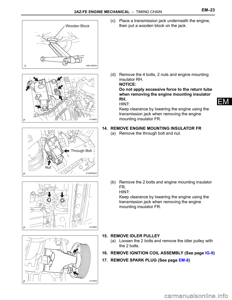
(c) Place a transmission jack underneath the engine,
then put a wooden block on the jack.
(d) Remove the 4 bolts, 2 nuts and engine mounting
insulator RH.
NOTICE:
Do not apply excessive force to the return tube
when removing the engine mounting insulator
RH.
HINT:
Keep clearance by lowering the engine using the
transmission jack when removing the engine
mounting insulator FR.
14. REMOVE ENGINE MOUNTING INSULATOR FR
(a) Remove the through bolt and nut.
(b) Remove the 2 bolts and engine mounting insulator
FR.
HINT:
Keep clearance by lowering the engine using the
transmission jack when removing the engine
mounting insulator FR.
15. REMOVE IDLER PULLEY
(a) Loosen the 2 bolts and remove the idler pulley with
the 2 bolts.
16. REMOVE IGNITION COIL ASSEMBLY (See page IG-9)
17. REMOVE SPARK PLUG (See page EM-8)
A061184E04
A124843
A124839E02
A124840
A114359
Page 598 of 2000

2AZ-FE ENGINE MECHANICAL – TIMING CHAINEM–41
EM
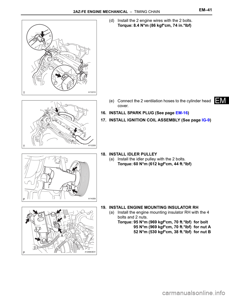
(d) Install the 2 engine wires with the 2 bolts.
Torque: 8.4 N*m (86 kgf*cm, 74 in.*lbf)
(e) Connect the 2 ventilation hoses to the cylinder head
cover.
16. INSTALL SPARK PLUG (See page EM-16)
17. INSTALL IGNITION COIL ASSEMBLY (See page IG-9)
18. INSTALL IDLER PULLEY
(a) Install the idler pulley with the 2 bolts.
Torque: 60 N*m (612 kgf*cm, 44 ft.*lbf)
19. INSTALL ENGINE MOUNTING INSULATOR RH
(a) Install the engine mounting insulator RH with the 4
bolts and 2 nuts.
Torque: 95 N*m (969 kgf*cm, 70 ft.*lbf) for bolt
95 N*m (969 kgf*cm, 70 ft.*lbf) for nut A
52 N*m (530 kgf*cm, 38 ft.*lbf) for nut B
A112210
A112209
A114359
A124843E01