2006 TOYOTA RAV4 ignition
[x] Cancel search: ignitionPage 556 of 2000

ES–322GR-FE ENGINE CONTROL SYSTEM – SFI SYSTEM
ES
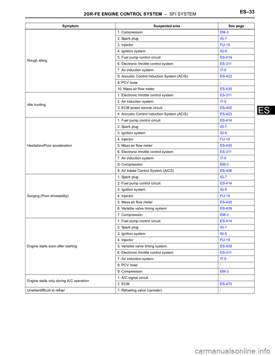
PROBLEM SYMPTOMS TABLE
HINT:
Use the table below to help determine the cause of the
problem symptom. The potential causes of the symptoms are
listed in order of probability in the "Suspected area" column of
the table. Check each symptom by checking the suspected
areas in the order they are listed. Replace parts as
necessary.
Symptom Suspected area See page
Engine does not crank (Does not start)1. BatteryCH-5
2. StarterST-8
3. Starter relayST-16
4. Park/neutral position switchAX-132
5. Immobiliser systemEI-3
No initial combustion (Does not start)1. ECM power source circuitES-402
2. Crankshaft position sensorES-448
3. VVT sensorES-214
4. Ignition systemIG-5
5. Fuel pump control circuitES-414
6. ECMES-470
7. VC output circuitES-408
Engine cranks normally but difficult to start1. Fuel pump control circuitES-414
2. CompressionEM-3
Difficult to start with cold engine1. Ignition systemIG-5
2. Spark plugIG-7
3. Fuel pump control circuitES-414
4. InjectorFU-15
Difficult to start with warm engine1. InjectorFU-15
2. Ignition systemIG-5
3. Spark plugIG-7
4. Fuel pump control circuitES-414
High engine idle speed1. Electronic throttle control systemES-311
2. A/C signal circuit -
3. ECM power source circuitES-402
4. Acoustic Control Induction System (ACIS)ES-423
Low engine idle speed (Poor idling)1. Electronic throttle control systemES-311
2. A/C signal circuit -
3. Fuel pump control circuitES-414
4. Air induction systemIT-5
5. Acoustic Control Induction System (ACIS)ES-423
6. PCV hose -
Page 557 of 2000

2GR-FE ENGINE CONTROL SYSTEM – SFI SYSTEMES–33
ES
Rough idling1. CompressionEM-3
2. Spark plugIG-7
3. InjectorFU-15
4. Ignition systemIG-5
5. Fuel pump control circuitES-414
6. Electronic throttle control systemES-311
7. Air induction systemIT-5
8. Acoustic Control Induction System (ACIS)ES-423
9. PCV hose -
10. Mass air flow meterES-435
Idle hunting1. Electronic throttle control systemES-311
2. Air induction systemIT-5
3. ECM power source circuitES-402
4. Acoustic Control Induction System (ACIS)ES-423
Hesitation/Poor acceleration1. Fuel pump control circuitES-414
2. Spark plugIG-7
3. Ignition systemIG-5
4. InjectorFU-15
5. Mass air flow meterES-435
6. Electronic throttle control systemES-311
7. Air induction systemIT-5
8. CompressionEM-3
9. Air Intake Control System (AICS)ES-426
Surging (Poor driveability)1. Spark plugIG-7
2. Fuel pump control circuitES-414
3. Ignition systemIG-5
4. InjectorFU-15
5. Mass air flow meterES-435
6. Variable valve timing systemES-439
7. CompressionEM-3
Engine stalls soon after starting1. Fuel pump control circuitES-414
2. Spark plugIG-7
3. Ignition systemIG-5
4. InjectorFU-15
5. Variable valve timing systemES-439
6. Electronic throttle control systemES-311
7. Air induction systemIT-5
8. PCV hose -
9. CompressionEM-3
Engine stalls only during A/C operation1. A/C signal circuit -
2. ECMES-470
Unable/difficult to refuel 1. Refueling valve (canister) -Symptom Suspected area See page
Page 558 of 2000

ES–342GR-FE ENGINE CONTROL SYSTEM – SFI SYSTEM
ES
TERMINALS OF ECM
1. CHECK ECM
(a) Measure the voltage of the ECM connector.
HINT:
The standard normal voltage between each pair of
ECM terminals is shown in the table below. The
appropriate conditions for checking each pair of
terminals are also indicated. The result of checks
should be compared with the standard normal
voltage for that pair of terminals, displayed in the
Specified Condition column. The illustration above
can be used as a reference to identify the ECM
terminal locations.
A107881E05
Symbol (Terminal No.) Wiring Color Terminal Description Condition Specified Condition
BATT (A9-20) - E1 (B30-81) W - BR Battery (for measuring
battery voltage and for
ECM memory)Always 9 to 14 V
+BM (A9-3) - E1 (B30-81) LG - BR Power source of throttle
actuatorAlways 9 to 14 V
IGSW (A9-28) - E1 (B30-81) B - BR Ignition switch Ignition switch ON 9 to 14 V
+B (A9-2) - E1 (B30-81) B - BR Power source of ECM Ignition switch ON 9 to 14 V
+B2 (A9-1) - E1 (B30-81) B - BR Power source of ECM Ignition switch ON 9 to 14 V
OC1+ (B30-58) - OC1- (B30-57) W - B Camshaft timing oil control
valve (OCV)Ignition switch ON Pulse generation (see
waveform 1)
OC2+ (B30-52) - OC2- (B30-51) BR - B Camshaft timing oil control
valve (OCV) (Intake side
(bank 2))Ignition switch ON Pulse generation
(see waveform 1)
OE1+ (B30-56) - OE1- (B30-55) R - LG Camshaft timing oil control
valve (OCV) (Exhaust side
(bank 1))Ignition switch ON Pulse generation
(see waveform 1)
OE2+ (B30-50) - OE2- (B30-49) W - B Camshaft timing oil control
valve (OCV) (Exhaust side
(bank 2))Ignition switch ON Pulse generation
(see waveform 1)
MREL (A9-44) - E1 (B30-81) O - BR EFI relay Ignition switch ON 9 to 14 V
VG (B30-72) - E2G (B30-73) GR - L-G Mass air flow meter Idling, Shift lever position P or N, A/
C switch OFF0.5 to 3.0 V
THA (B30-71) - ETHA (B30-74) P - G-R Intake air temperature
sensorIdling, Intake air temperature 20
C
(68F)0.5 to 3.4 V
Page 559 of 2000

2GR-FE ENGINE CONTROL SYSTEM – SFI SYSTEMES–35
ES
THW (B30-79) - ETHW (B30-78) L - BR Engine coolant
temperature sensorIdling, Engine coolant temperature
80
C (176F)0.2 to 1.0 V
VCTA (B30-96) - ETA (B30-97) B - W Power source of throttle
position sensor (specific
voltage)Ignition switch ON 4.5 to 5.5 V
VTA1 (B30-98) - ETA (B30-97) Y - W Throttle position sensor
(for engine control)Ignition switch ON,
Throttle valve fully closed0.5 to 1.1 V
Ignition switch ON,
Throttle valve fully open3.3 to 4.9 V
VTA2 (B30-99) - ETA (B30-97) GR - W Throttle position sensor
(for sensor malfunction
detection)Ignition switch ON,
Throttle valve fully closed2.1 to 3.1 V
Ignition switch ON,
Throttle valve fully open4.6 to 5.0 V
VPA (A9-55) - EPA (A9-59) W - Y Accelerator pedal position
sensor (for engine control)Ignition switch ON,
Accelerator pedal released0.5 to 1.1 V
Ignition switch ON,
Accelerator pedal fully depressed2.6 to 4.5 V
VPA2 (A9-56) - EPA2 (A9-60) R - O Accelerator pedal position
sensor (for sensor
malfunctioning detection)Ignition switch ON,
Accelerator pedal released1.2 to 2.0 V
Ignition switch ON,
Accelerator pedal fully depressed3.4 to 5.0 V
VCPA (A9-57) - EPA (A9-59) B - Y Power source of
accelerator pedal position
sensor (for VPA)Ignition switch ON 4.5 to 5.5 V
VCP2 (A9-58) - EPA2 (A9-60) L - O Power source of
accelerator pedal position
sensor (for VPA2)Ignition switch ON 4.5 to 5.5 V
HA1A (B30-86) - E04 (B30-23)
HA2A (B30-109) - E04 (B30-23) G - BR
B - BRA/F sensor heater Idling Below 3.0 V
Ignition switch ON 9 to 14 V
A1A+ (B30-93) - E1 (B30-81) W -BR A/F sensor Ignition switch ON 3.3 V*
A1A- (B30-116) - E1 (B30-81) BR - BR A/F sensor Ignition switch ON3.0 V*
A2A+ (B30-120) - E1 (B30-81) L - BR A/F sensor Ignition switch ON 3.3 V*
A2A- (B30-119) - E1 (B30-81) Y - BR A/F sensor Ignition switch ON 3.0 V*
HT1B (B30-48) - E03 (B30-104)
HT2B (B30-47) - E03 (B30-104)LG - BR
Y - BRHeated oxygen sensor
heaterIdling Below 3.0 V
Ignition switch ON 9 to 14 V
OX1B (B30-88) - EX1B (B30-65)
OX2B (B30-87) - EX2B- (B30-64)W - GR
B - B-WHeated oxygen sensor Engine speed maintained at 2,500
rpm for 2 minutes after warming up
sensorPulse generation (see
waveform 2)
#10 (B30-45) - E01 (B30-22)
#20 (B30-85) - E01 (B30-22)
#30 (B30-44) - E01 (B30-22)
#40 (B30-84) - E01 (B30-22)
#50 (B30-43) - E01 (B30-22)
#60 (B30-83) - E01 (B30-22)Y - BR
W - BR
B - BR
BR - BR
L - BR
G - BRInjector Ignition switch ON 9 to 14 V
Idling Pulse generation (see
waveform 3)
KNK1 (B30-95) - EKNK (B30-94)
KNK2 (B30-118) - EKN2 (B30-
11 7 )R - G
B - WKnock sensor Engine speed maintained at 4,000
rpm after warming up enginePulse generation (see
waveform 4)
VCV1 (B30-115) - E1 (B30-81) G-R - BR Power source for VVT
sensor (specific voltage)Ignition switch ON 4.5 to 5.0 V
VCV2 (B30-113) - E1 (B30-81) V - BR Power source for VVT
sensor (specific voltage)Ignition switch ON 4.5 to 5.0 V
VCE1 (B30-114) - E1 (B30-81) GR - BR Power source for VVT
sensor specific voltage)Ignition switch ON 4.5 to 5.0 V
VCE2 (B30-112) - E1 (B30-81) Y - BR Power source for VVT
sensor (specific voltage)Ignition switch ON 4.5 to 5.0 V
VV1+ (B30-69) - VV1- (B30-92) P - L-B Variable valve timing
(VVT) sensor (Intake side
(bank 1))Idling Pulse generation
(see waveform 5) Symbol (Terminal No.) Wiring Color Terminal Description Condition Specified Condition
Page 560 of 2000

ES–362GR-FE ENGINE CONTROL SYSTEM – SFI SYSTEM
ES
VV2+ (B30-67) - VV2- (B30-90) W - B Variable valve timing
(VVT) sensor (Intake side
(bank 2))Idling Pulse generation
(see waveform 5)
EV1+ (B30-68) - EV1- (B30-91) Y - G Variable valve timing
(VVT) sensor (Exhaust
side (bank 1))Idling Pulse generation
(see waveform 5)
EV2+ (B30-66) - EV2- (B30-89) R - L Variable valve timing
(VVT) sensor (Exhaust
side (bank 2))Idling Pulse generation
(see waveform 5)
NE+ (B30-110) - NE- (B30-111) G - R Crankshaft position sensor Idling Pulse generation (see
waveform 5)
IGT1 (B30-40) - E1 (B30-81)
IGT2 (B30-39) - E1 (B30-81)
IGT3 (B30-38) - E1 (B30-81)
IGT4 (B30-37) - E1 (B30-81)
IGT5 (B30-36) - E1 (B30-81)
IGT6 (B30-35) - E1 (B30-81)W - BR
G-R - BR
G - BR
LG - BR
P - BR
V - BRIgnition coil (ignition
signal)Idling Pulse generation (see
waveform 6)
IGF1 (B30-106) - E1 (B30-81) Y - BR Ignition coil (ignition
confirmation signal)Ignition switch ON 4.5 to 5.5 V
Idling Pulse generation (see
waveform 6)
PRG (B30-108) - E1 (B30-81) LG - BR Purge VSV Ignition switch ON 9 to 14 V
Idling Pulse generation (see
waveform 7)
SPD (A9-8) - E1 (B30-81) V - BR Speed signal from
combination meterDriving at 20 km/h (12 mph) Pulse generation (see
waveform 8)
STA (A9-48) - E1 (B30-81) LG - BR Starter signal Cranking 5.5 V or more
NSW (B30-62) - E1 (B30-81) G-R - BR Starter relay control Ignition switch ON Below 1.5 V
Cranking 6.0 V or more
STP (A9-36) - E1 (B30-81) L - BR Stop light switch Brake pedal depressed 7.5 to 14 V
Brake pedal released Below 1.5 V
ST1- (A9-35) - E1 (B30-81) GR - BR Stop light switch
(opposite to STP terminal)Ignition switch ON,
Brake pedal depressedBelow 1.5 V
Ignition switch ON,
Brake pedal released7.5 to 14 V
M+ (B30-19) - ME01 (B30-20) G - BR Throttle actuator Idling with warm engine Pulse generation (see
waveform 9)
M- (B30-18) - ME01 (B30-20) R - BR Throttle actuator Idling with warm engine Pulse generation (see
waveform 10)
FC (A9-7) - E1 (B30-81) W - BR Fuel pump control Ignition switch ON 9 to 14 V
Idling Below 1.5 V
FPR (B30-59) - E1 (B30-81) W - BR Fuel pump control Cranking 9 to 14 V
FPR (B30-59) - E1 (B30-81) W - BR Fuel pump control Idling 9 to 14 V
W (A9-24) - E1 (B30-81) R - BR MIL Ignition switch ON Below 1.5 V
Idling 9 to 14 V
TC (A9-27) - E1 (B30-81) G - BR Terminal TC of DLC3 Ignition switch ON 9 to 14 V
TACH (A9-15) - E1 (B30-81) GR - BR Engine speed Idling Pulse generation (see
waveform 11)
VPMP (A9-42) - E1 (B30-81) W - BR Vent valve (built into
canister pump module)Ignition switch ON 9 to 14 V
MPMP (A9-34) - E1 (B30-81) B - BR Leak detection pump (built
into canister pump
module)Leak detection pump OFF Below 3 V
Leak detection pump ON 9 to 14 V
VCPP (B30-75) - EPPM (B30-76) V - BR Power source for canister
pressure sensor (specific
voltage)Ignition switch ON 4.5 to 5.5 V Symbol (Terminal No.) Wiring Color Terminal Description Condition Specified Condition
Page 561 of 2000

2GR-FE ENGINE CONTROL SYSTEM – SFI SYSTEMES–37
ES
HINT:
*: The ECM terminal voltage is constant regardless
of the output voltage from the sensor.
(b) WAVEFORM 1
Camshaft timing oil control valve (OCV)
PPMP (B30-77) - EPPM (B30-76) L - BR Canister pressure sensor
(built into canister pump
module)Ignition switch ON 3 to 3.6 V
ELS (A9-31) - E1 (B30-81) O - BR Electric load Taillight switch ON7.5 to 14 V
Taillight switch OFF Below 1.5 V
ELS2 (A9-33) - E1 (B30-81) G - BR Electric load Defogger switch ON7.5 to 14 V
Defogger switch OFF Below 1.5 V
ALT (B30-32) - E1 (B30-81) P - BR Generator Ignition switch ON 9 to 14 V
CANH (A9-41) - E1 (B30-81) Y - BR CAN communication line Ignition switch ON Pulse generation (see
waveform 12)
CANL (A9-49) - E1 (B30-81) W - BR CAN communication line Ignition switch ON Pulse generation (see
waveform 13)
VCIB (B30-80) - EIB (B30-101) LG - P Battery current sensor Ignition switch ON 4.5 to 5.5 V
IB (B30-100) - EIB (B30-101) R - P Battery current sensor Ignition switch ON 0.5 to 2.5 V
THB (B30-103) - EIB (B30-101) G-R - P Battery temperature
sensorIgnition switch ON, battery
temperature -30 to 80
C (-22 to
176
F)0.5 to 4.5 V
RLO (B30-31) - E1 (B30-81) Y - BR Generator After engine warmed up, during
charging control, vehicle driven at
constant speedPulse generation (see
waveform 14)
RLO (B30-31) - E1 (B30-81) Y - BR Generator After engine warmed up, during
charging control, vehicle
acceleratedPulse generation (see
waveform 15)
RLO (B30-31) - E1 (B30-81) Y - BR Generator After engine warmed up, during
charging control, vehicle
deceleratedPulse generation (see
waveform 16)
AICV (A9-4) - E1 (B30-81) L - BR VSV for air intake control
system operation signalIgnition switch ON 9 to 14 V
ACIS (B30-107) - E1 (B30-81) R - BR VSV for ACIS (Acoustic
Control Induction System)
operation signalIgnition switch ON 9 to 14 V Symbol (Terminal No.) Wiring Color Terminal Description Condition Specified Condition
A093229E02
Symbol (Terminal No.) Between OC1+ and OC1-
Between OC2+ and OC2-
Between OE1+ and OE1-
Between OE2+ and OE2-
Tester Range 5 V/DIV., 1 msec./DIV.
Condition Idling
Page 564 of 2000

ES–402GR-FE ENGINE CONTROL SYSTEM – SFI SYSTEM
ES
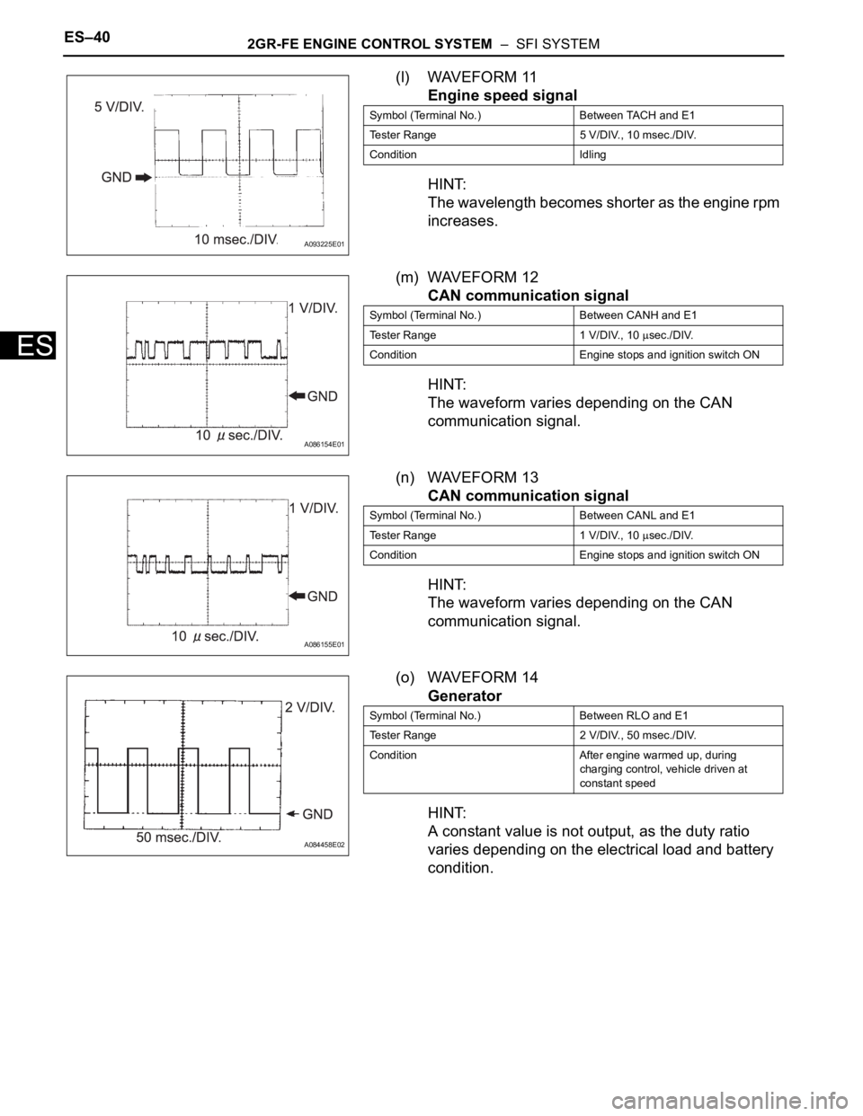
(l) WAVEFORM 11
Engine speed signal
HINT:
The wavelength becomes shorter as the engine rpm
increases.
(m) WAVEFORM 12
CAN communication signal
HINT:
The waveform varies depending on the CAN
communication signal.
(n) WAVEFORM 13
CAN communication signal
HINT:
The waveform varies depending on the CAN
communication signal.
(o) WAVEFORM 14
Generator
HINT:
A constant value is not output, as the duty ratio
varies depending on the electrical load and battery
condition.
A093225E01
Symbol (Terminal No.) Between TACH and E1
Tester Range 5 V/DIV., 10 msec./DIV.
Condition Idling
A086154E01
Symbol (Terminal No.) Between CANH and E1
Tester Range 1 V/DIV., 10
sec./DIV.
Condition Engine stops and ignition switch ON
A086155E01
Symbol (Terminal No.) Between CANL and E1
Tester Range 1 V/DIV., 10
sec./DIV.
Condition Engine stops and ignition switch ON
A084458E02
Symbol (Terminal No.) Between RLO and E1
Tester Range 2 V/DIV., 50 msec./DIV.
Condition After engine warmed up, during
charging control, vehicle driven at
constant speed
Page 567 of 2000

2GR-FE ENGINE CONTROL SYSTEM – SFI SYSTEMES–43
ES
3. 2 TRIP DETECTION LOGIC
When a malfunction is first detected, the malfunction is
temporarily stored in the ECM memory (1st trip). If the
same malfunction is detected during the next
subsequent drive cycle, the MIL is illuminated (2nd trip).
4. FREEZE FRAME DATA
Freeze frame data records the engine conditions (fuel
system, calculated engine load, engine coolant
temperature, fuel trim, engine speed, vehicle speed,
etc.) when malfunctions are detected. When
troubleshooting, freeze frame data can help determine if
the vehicle was moving or stationary, if the engine was
warmed up or not, if the air-fuel ratio was lean or rich,
and other data from the time the malfunction occurred.
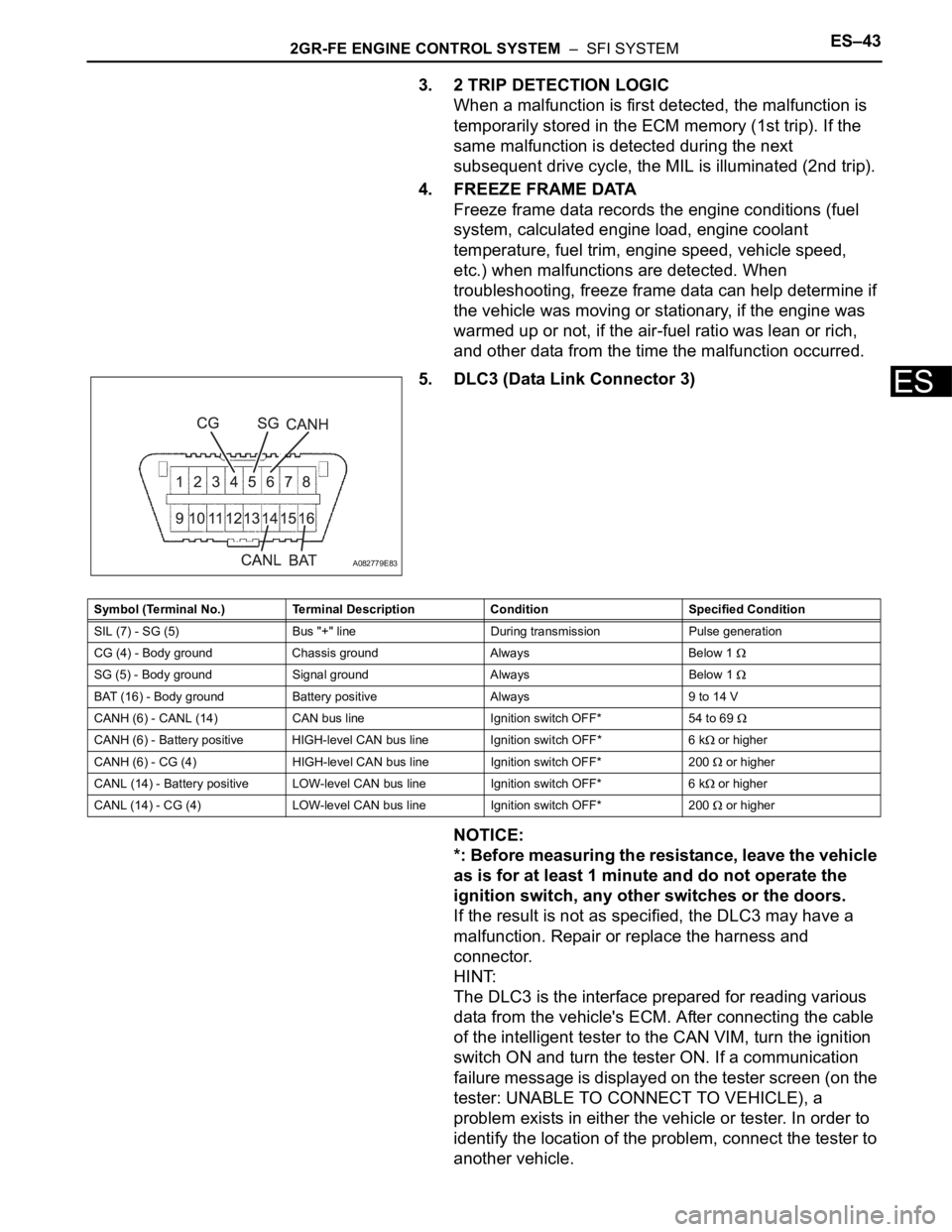
5. DLC3 (Data Link Connector 3)
NOTICE:
*: Before measuring the resistance, leave the vehicle
as is for at least 1 minute and do not operate the
ignition switch, any other switches or the doors.
If the result is not as specified, the DLC3 may have a
malfunction. Repair or replace the harness and
connector.
HINT:
The DLC3 is the interface prepared for reading various
data from the vehicle's ECM. After connecting the cable
of the intelligent tester to the CAN VIM, turn the ignition
switch ON and turn the tester ON. If a communication
failure message is displayed on the tester screen (on the
tester: UNABLE TO CONNECT TO VEHICLE), a
problem exists in either the vehicle or tester. In order to
identify the location of the problem, connect the tester to
another vehicle.
A082779E83
Symbol (Terminal No.) Terminal Description Condition Specified Condition
SIL (7) - SG (5) Bus "+" line During transmission Pulse generation
CG (4) - Body ground Chassis ground Always Below 1
SG (5) - Body ground Signal ground Always Below 1
BAT (16) - Body ground Battery positive Always 9 to 14 V
CANH (6) - CANL (14) CAN bus line Ignition switch OFF* 54 to 69
CANH (6) - Battery positive HIGH-level CAN bus line Ignition switch OFF* 6 k or higher
CANH (6) - CG (4) HIGH-level CAN bus line Ignition switch OFF* 200
or higher
CANL (14) - Battery positive LOW-level CAN bus line Ignition switch OFF* 6 k
or higher
CANL (14) - CG (4) LOW-level CAN bus line Ignition switch OFF* 200
or higher