2006 TOYOTA RAV4 ignition
[x] Cancel search: ignitionPage 453 of 2000
LI–126LIGHTING – IGNITION KEY CYLINDER LIGHT
LI
INSTALLATION
1. INSTALL TRANSPONDER KEY AMPLIFIER (See page
SR-18)
2. INSTALL STEERING COLUMN COVER (See page SR-
20)
3. INSTALL STEERING WHEEL ASSEMBLY (See page
SR-21)
4. PLACE FRONT WHEELS FACING STRAIGHT AHEAD
5. INSPECT STEERING WHEEL CENTER POINT
6. INSTALL STEERING PAD ASSEMBLY (See page RS-
336)
7. CONNECT CABLE TO NEGATIVE BATTERY
TERMINAL
8. INSPECT STEERING PAD ASSEMBLY (See page RS-
337)
9. CHECK SRS WARNING LIGHT
(a) Check the SRS warning light (see page RS-337).
Page 456 of 2000

DL–4DOOR LOCK – POWER DOOR LOCK CONTROL SYSTEM
DL
SYSTEM DESCRIPTION
1. POWER DOOR LOCK SYSTEM DESCRIPTION
(a) The power door lock system locks / unlocks all
doors with a one-touch operation.
• The door control switch of the power window
regulator master switch or door control switch on
passenger side sends lock / unlock request
signals to the main body ECU. Then, the main
body ECU sends these requests to the lock
motors in each door to lock / unlock all the doors
simultaneously.
• Operating the driver side door lock using a key
sends lock / unlock request signals to the main
body ECU.
2. COMPONENTS
3. FUNCTIONS
This system is controlled by the main body ECU. The
main body ECU outputs signals to each door lock motor.
The door lock control system in the vehicle has the
following functions:
Components Function
Door control switch on power window regulator master switch Locks / unlocks all doors
Door control switch Locks / unlocks all doors
Door courtesy switch • Placed on each door.
• Detects door status (open or closed) and outputs data to main
body ECU.
• Turns on when door is open and off when door is closed.
Driver door lock • Built-in motor locks / unlocks door.
• Built-in door control switch (key-linked) detects door key
operation's door status (locked or unlocked) and outputs data to
main body ECU.
• Built-in position switch detects door status (locked or unlocked)
and outputs data to main body ECU. This switch turns off when
door is locked and on when door is unlocked.
• Front passenger door lock
• Rear door lock LH
• Rear door lock RH
• Back door lockBuilt-in motor locks / unlocks door.
Functions Outlines
Key-linked lock and unlock function Linked with key cylinder. Locks / unlocks all doors when lock / unlock
operation is possible.
Key lock-in prevention function When key is inserted in ignition key cylinder and door lock operation is
performed, all doors are unlocked.
Manual unlock prohibition function Performing door lock operation with transmitter or key disables unlock
operation by door control switch.
2-step unlock function Unlocks only driver door by turning key cylinder once and unlocks
other doors by turning it twice.
Page 468 of 2000
ES–142AZ-FE ENGINE CONTROL SYSTEM – SFI SYSTEM
ES
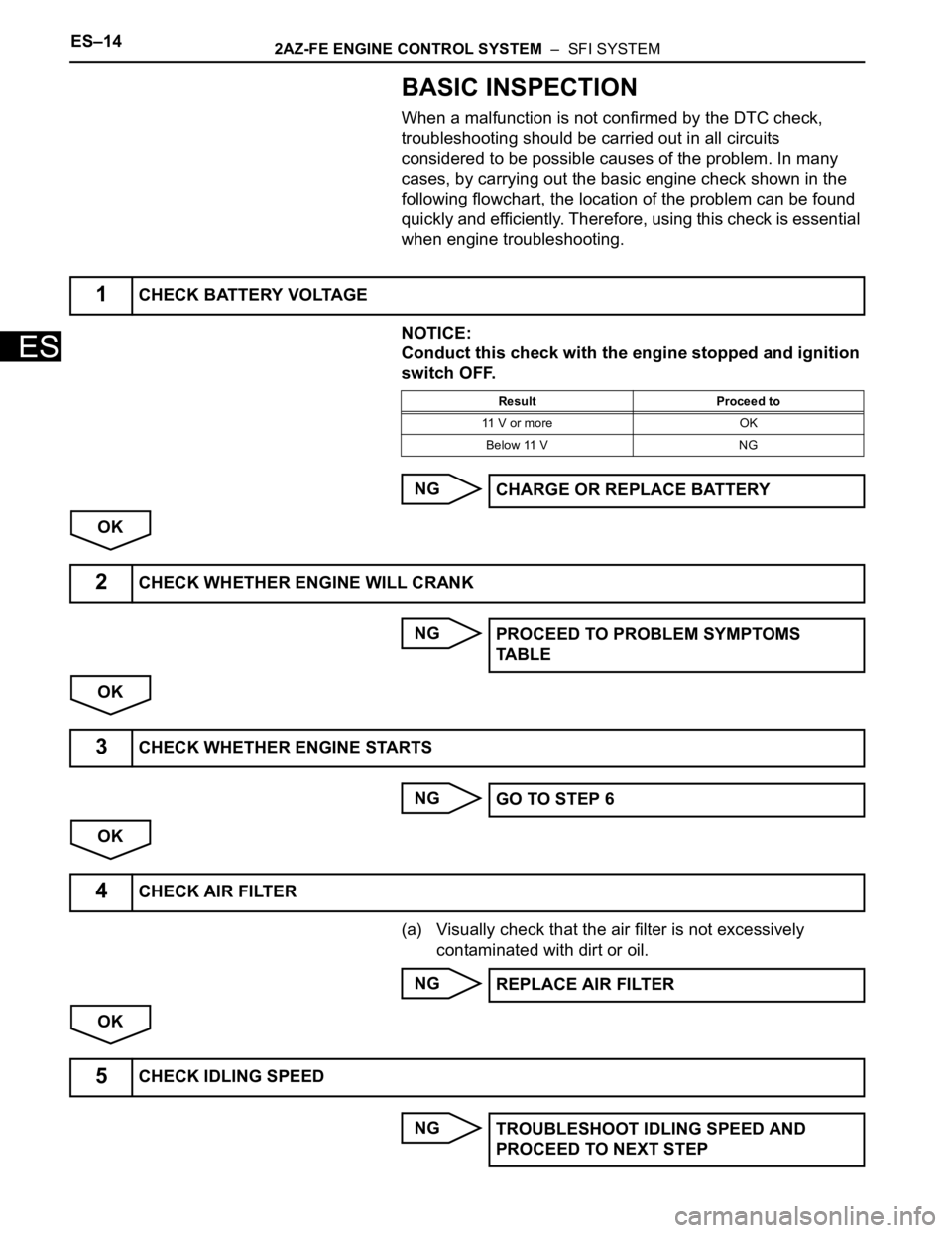
BASIC INSPECTION
When a malfunction is not confirmed by the DTC check,
troubleshooting should be carried out in all circuits
considered to be possible causes of the problem. In many
cases, by carrying out the basic engine check shown in the
following flowchart, the location of the problem can be found
quickly and efficiently. Therefore, using this check is essential
when engine troubleshooting.
NOTICE:
Conduct this check with the engine stopped and ignition
switch OFF.
NG
OK
NG
OK
NG
OK
(a) Visually check that the air filter is not excessively
contaminated with dirt or oil.
NG
OK
NG
1CHECK BATTERY VOLTAGE
Result Proceed to
11 V or more OK
Below 11 V NG
CHARGE OR REPLACE BATTERY
2CHECK WHETHER ENGINE WILL CRANK
PROCEED TO PROBLEM SYMPTOMS
TA B L E
3CHECK WHETHER ENGINE STARTS
GO TO STEP 6
4CHECK AIR FILTER
REPLACE AIR FILTER
5CHECK IDLING SPEED
TROUBLESHOOT IDLING SPEED AND
PROCEED TO NEXT STEP
Page 471 of 2000
2AZ-FE ENGINE CONTROL SYSTEM – SFI SYSTEMES–17
ES
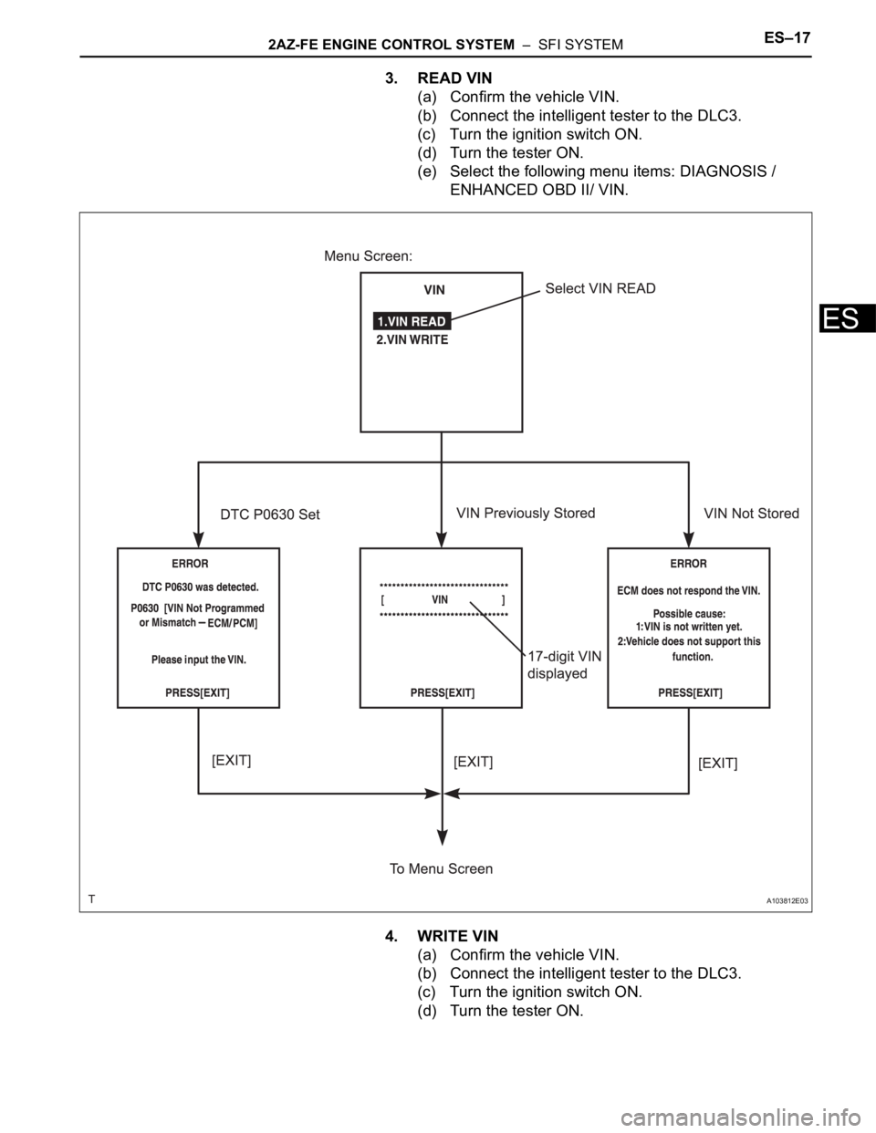
3. READ VIN
(a) Confirm the vehicle VIN.
(b) Connect the intelligent tester to the DLC3.
(c) Turn the ignition switch ON.
(d) Turn the tester ON.
(e) Select the following menu items: DIAGNOSIS /
ENHANCED OBD II/ VIN.
4. WRITE VIN
(a) Confirm the vehicle VIN.
(b) Connect the intelligent tester to the DLC3.
(c) Turn the ignition switch ON.
(d) Turn the tester ON.
A103812E03
Page 475 of 2000
2AZ-FE ENGINE CONTROL SYSTEM – SFI SYSTEMES–21
ES
CHECKING MONITOR STATUS
The purpose of the monitor result (mode 06) is to allow
access to the results of on-board diagnostic monitoring tests
of specific components/systems that are not continuously
monitored. Examples are catalysts, evaporative emissions
(EVAP) and thermostats.
The monitor result allows the OBD II scan tool to display the
monitor status, test value, minimum test limit and maximum
test limit. These data are displayed after the vehicle has been
driven to run the monitor.
When the test value is not between the minimum and
maximum test limits, the ECM (PCM) interprets this as a
malfunction. If the test value is on the borderline of the test
limits, the component is likely to malfunction in the near
future.
Perform the following instruction to view the monitor status.
Although this instruction refers to the Lexus/Toyota diagnostic
tester, it can be checked using a generic OBD II scan tool.
Refer to your scan tool operator's manual for specific
procedural information.
1. PERFORM MONITOR DRIVE PATTERN
(a) Connect the intelligent tester to the DLC3.
(b) Turn the ignition switch and the tester ON.
(c) Clear the DTCs (see page ES-35).
(d) Run the vehicle in accordance with the applicable
drive pattern described in READINESS MONITOR
DRIVE PATTERN (see page ES-19). Do not turn the
ignition switch OFF.
NOTE:
The test results will be lost if the ignition
switch is turned OFF.
2. ACCESS MONITOR RESULT
(a) Select the following items from the intelligent tester
menus: DIAGNOSIS, ENHANCED OBD II,
MONITOR INFO and MONITOR RESULT. The
monitor status appears after the component name.
• INCMP: The component has not been monitored
yet.
• PASS: The component is functioning normally.
• FAIL: The component is malfunctioning.
(b) Confirm that the component is either PASS or FAIL.
(c) Select the component and press ENTER. The
accuracy test value appears if the monitor status is
either PASS or FAIL.
3. CHECK COMPONENT STATUS
(a) Compare the test value with the minimum test limit
(MIN LIMIT) and maximum test limit (MAX LIMIT).
Page 476 of 2000

ES–222AZ-FE ENGINE CONTROL SYSTEM – SFI SYSTEM
ES
(b) If the test value is between the minimum and
maximum test limits, the component is functioning
normally. If not, the component is malfunctioning.
The test value is usually not near the test limits. If
the test value is near the test limits, the component
is likely to malfunction in the near future.
HINT:
The monitor result might on rare occasions be
PASS even if the malfunction indicator lamp (MIL) is
illuminated. This indicates the system malfunctioned
on a previous driving cycle. This might be caused by
an intermittent problem.
4. MONITOR RESULT INFORMATION
If you use a generic scan tool, multiply the test value by
the scaling value listed below.
A/F Sensor (Sensor 1)
HO2 Sensor (Sensor 2)
Catalyst
EVAP
Misfire
Monitor ID Test ID Scaling Unit Description
$01 $8E Multiply by 0.001 V A/F sensor deterioration level
$01 $91 Multiply by 0.004 mA A/F sensor current
Monitor ID Test ID Scaling Unit Description
$02 $07 Multiply by 0.001 V Minimum sensor voltage
$02 $08 Multiply by 0.001 V Maximum sensor voltage
$02 $8F Multiply by 0.0003 g Maximum oxygen storage capacity
Monitor ID Test ID Scaling Unit Description
$21 $A9 Multiply by 0.0003 No dimension Oxygen storage capacity of catalyst
Monitor ID Test ID Scaling Unit Description
$3D $C9 Multiply by 0.001 kPa Test value for small leak (P0456)
$3D $CA Multiply by 0.001 kPa Test value for gross leak (P0455)
$3D $CB Multiply by 0.001 kPa Test value for leak detection pump stuck OFF (P2401)
$3D $CD Multiply by 0.001 kPa Test value for leak detection pump stuck ON (P2402)
$3D $CE Multiply by 0.001 kPa Test value for vent valve stuck OFF (P2420)
$3D $CF Multiply by 0.001 kPa Test value for vent valve stuck ON (P2419)
$3D $D0 Multiply by 0.001 kPa Test value for reference orifice low flow (P043E)
$3D $D1 Multiply by 0.001 kPa Test value for reference orifice high flow (P043F)
$3D $D4 Multiply by 0.001 kPa Test value for purge VSV stuck closed (P0441)
$3D $D5 Multiply by 0.001 kPa Test value for purge VSV stuck open (P0441)
$3D $D7 Multiply by 0.001 kPa Test value for purge flow insufficient (P0441)
Monitor ID Test ID Scaling Unit Description
$A1 $0B Multiply by 1 TimeExponential Weighted Moving Average (EWMA) misfire for all
cylinders:
EWMA = Total misfire counts for last driving cycle * 0.1 + Last
EWMA * 0.9
Misfire counts for last 10 driving cycles - Total
$A1 $0C Multiply by 1 TimeIgnition switch ON: Total misfire counts for last driving cycle
Engine running: Total misfire counts for current driving cycle
Misfire counts for last or current driving cycle - all cylinders
Page 477 of 2000

2AZ-FE ENGINE CONTROL SYSTEM – SFI SYSTEMES–23
ES
$A2 $0B Multiply by 1 TimeExponential Weighted Moving Average (EWMA) misfire for
cylinder 1:
EWMA = Total misfire counts for last driving cycle * 0.1 + Last
EWMA * 0.9
Misfire counts for last 10 driving cycles - Total
$A2 $0C Multiply by 1 TimeIgnition switch ON: Total misfire counts for last driving cycle
Engine running: Total misfire counts for current driving cycle
Misfire counts for last or current driving cycle - cylinder 1
$A3 $0B Multiply by 1 TimeExponential Weighted Moving Average (EWMA) misfire for
cylinder 2:
EWMA = Total misfire counts for last driving cycle * 0.1 + Last
EWMA * 0.9
Misfire counts for last 10 driving cycles - Total
$A3 $0C Multiply by 1 TimeIgnition switch ON: Total misfire counts for last driving cycle
Engine running: Total misfire counts for current driving cycle
Misfire counts for last or current driving cycle - cylinder 2
$A4 $0B Multiply by 1 TimeExponential Weighted Moving Average (EWMA) misfire for
cylinder 3:
EWMA = Total misfire counts for last driving cycle * 0.1 + Last
EWMA * 0.9
Misfire counts for last 10 driving cycles - Total
$A4 $0C Multiply by 1 TimeIgnition switch ON: Total misfire counts for last driving cycle
Engine running: Total misfire counts for current driving cycle
Misfire counts for last or current driving cycle - cylinder 3
$A5 $0B Multiply by 1 TimeExponential Weighted Moving Average (EWMA) misfire for
cylinder 4:
EWMA = Total misfire counts for last driving cycle * 0.1 + Last
EWMA * 0.9
Misfire counts for last 10 driving cycles - Total
$A5 $0C Multiply by 1 TimeIgnition switch ON: Total misfire counts for last driving cycle
Engine running: Total misfire counts for current driving cycle
Misfire counts for last or current driving cycle - cylinder 4 Monitor ID Test ID Scaling Unit Description
Page 479 of 2000
2AZ-FE ENGINE CONTROL SYSTEM – SFI SYSTEMES–25
ES
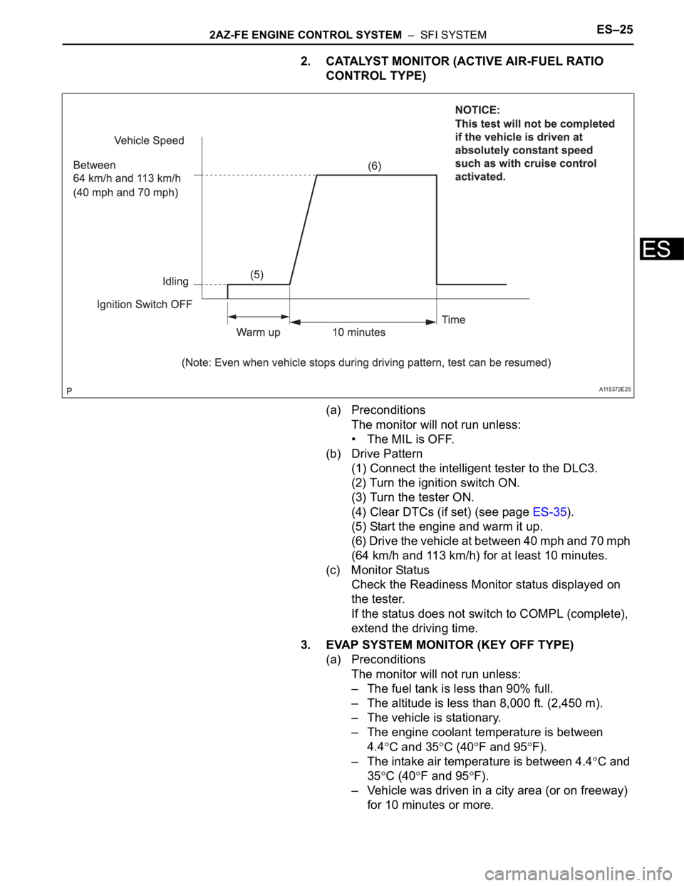
2. CATALYST MONITOR (ACTIVE AIR-FUEL RATIO
CONTROL TYPE)
(a) Preconditions
The monitor will not run unless:
• The MIL is OFF.
(b) Drive Pattern
(1) Connect the intelligent tester to the DLC3.
(2) Turn the ignition switch ON.
(3) Turn the tester ON.
(4) Clear DTCs (if set) (see page ES-35).
(5) Start the engine and warm it up.
(6) Drive the vehicle at between 40 mph and 70 mph
(64 km/h and 113 km/h) for at least 10 minutes.
(c) Monitor Status
Check the Readiness Monitor status displayed on
the tester.
If the status does not switch to COMPL (complete),
extend the driving time.
3. EVAP SYSTEM MONITOR (KEY OFF TYPE)
(a) Preconditions
The monitor will not run unless:
– The fuel tank is less than 90% full.
– The altitude is less than 8,000 ft. (2,450 m).
– The vehicle is stationary.
– The engine coolant temperature is between
4.4
C and 35C (40F and 95F).
– The intake air temperature is between 4.4
C and
35
C (40F and 95F).
– Vehicle was driven in a city area (or on freeway)
for 10 minutes or more.
A115372E25