Page 208 of 2000

FU–62AZ-FE FUEL – FUEL SYSTEM
FU
ON-VEHICLE INSPECTION
1. CHECK FUEL PUMP OPERATION
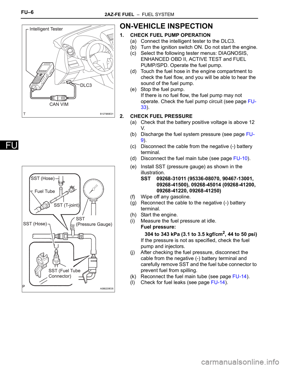
(a) Connect the intelligent tester to the DLC3.
(b) Turn the ignition switch ON. Do not start the engine.
(c) Select the following tester menus: DIAGNOSIS,
ENHANCED OBD II, ACTIVE TEST and FUEL
PUMP/SPD. Operate the fuel pump.
(d) Touch the fuel hose in the engine compartment to
check the fuel flow, and you will be able to hear the
sound of the fuel pump.
(e) Stop the fuel pump.
If there is no fuel flow, the fuel pump may not
operate. Check the fuel pump circuit (see page FU-
33).
2. CHECK FUEL PRESSURE
(a) Check that the battery positive voltage is above 12
V.
(b) Discharge the fuel system pressure (see page FU-
9).
(c) Disconnect the cable from the negative (-) battery
terminal.
(d) Disconnect the fuel main tube (see page FU-10).
(e) Install SST (pressure gauge) as shown in the
illustration.
SST 09268-31011 (95336-08070, 90467-13001,
09268-41500), 09268-45014 (09268-41200,
09268-41220, 09268-41250)
(f) Wipe off any gasoline.
(g) Reconnect the cable to the negative (-) battery
terminal.
(h) Start the engine.
(i) Measure the fuel pressure at idle.
Fuel pressure:
304 to 343 kPa (3.1 to 3.5 kgf/cm
2, 44 to 50 psi)
If the pressure is not as specified, check the fuel
pump and injectors.
(j) After checking the fuel pressure, disconnect the
cable from the negative (-) battery terminal and
carefully remove SST and the fuel tube connector to
prevent fuel from spilling.
(k) Reconnect the fuel main tube (see page FU-14).
(l) Check for fuel leaks (see page FU-14).
B127989E01
A088229E05
Page 210 of 2000

INTRODUCTION – REPAIR INSTRUCTIONIN–27
IN
5. Lighting System
WIRLS BUZZ OPER ONFunction that makes wireless
buzzer sound for answer-back
when transmitter LOCK /
UNLOCK switch pressedON / OFF
OPEN DOOR WARN ONIf door is not completely closed
and transmitter LOCK switch is
pressed, this function sounds a
buzzer for 10 secondsON / OFF
WIRELESS OPER ONON / OFF of wireless door lock
functionON / OFF
ALARM FUNCTION ONOperates security alarm when
PANIC switch on transmitter
continuously pressed for 1
secondON / OFF
UNLOCK / 2 OPER ONFunction that unlocks driver side
door when unlock switch on
transmitter is pressed once, and
unlocks all doors when pressed
twice. If setting is OFF, pressing
unlock switch once makes all
doors unlock.ON / OFF
AUTO LOCK DELAY 30sThis function controls amount of
time from unlocking doors to
automatic re-locking function30s / 60s Display (Item) Default Contents Setting
Display (Item) Default Contents Setting
LIGHTING TIME
(Lighting Time)15 secondsChanges illumination duration
after door closure.
(It will quickly fade out in case of
turning ignition switch ON.)7.5/15/30 (seconds)
I/L ON /ACC OFF
(Room light illuminates when
ignition switch turned OFF)ONIlluminates light when ignition
switch turned to ACC.
(Room light illuminated when
interior light switch in DOOR
position)ON / OFF
I/L ON / UNLOCK
(Room light illuminates when
door key unlocked.)ONFunction to light up room light
when unlocking with door key
cylinder.
(Room light illuminated when
interior light switch in DOOR
position)ON / OFF
LIGHT CONTROL ONFunction to light up foot light
when ignition switch is ON and
shift position is not P.ON / OFF
Page 218 of 2000

INTRODUCTION – HOW TO TROUBLESHOOT ECU CONTROLLED SYSTEMSIN–41
IN
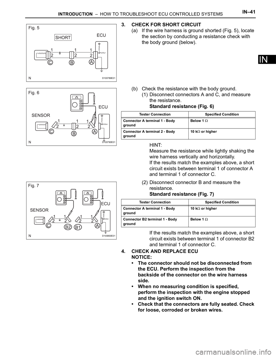
3. CHECK FOR SHORT CIRCUIT
(a) If the wire harness is ground shorted (Fig. 5), locate
the section by conducting a resistance check with
the body ground (below).
(b) Check the resistance with the body ground.
(1) Disconnect connectors A and C, and measure
the resistance.
Standard resistance (Fig. 6)
HINT:
Measure the resistance while lightly shaking the
wire harness vertically and horizontally.
If the results match the examples above, a short
circuit exists between terminal 1 of connector A
and terminal 1 of connector C.
(2) Disconnect connector B and measure the
resistance.
Standard resistance (Fig. 7)
If the results match the examples above, a short
circuit exists between terminal 1 of connector B2
and terminal 1 of connector C.
4. CHECK AND REPLACE ECU
NOTICE:
• The connector should not be disconnected from
the ECU. Perform the inspection from the
backside of the connector on the wire harness
side.
• When no measuring condition is specified,
perform the inspection with the engine stopped
and the ignition switch ON.
• Check that the connectors are fully seated. Check
for loose, corroded or broken wires.
D100789E01
D100790E01
Tester Connection Specified Condition
Connector A terminal 1 - Body
groundBelow 1
Connector A terminal 2 - Body
ground10 k or higher
D100800E01
Tester Connection Specified Condition
Connector A terminal 1 - Body
ground10 k
or higher
Connector B2 terminal 1 - Body
ground Below 1
Page 220 of 2000

IN–48INTRODUCTION – TERMS
IN
GLOSSARY OF SAE AND TOYOTA
TERMS
This glossary lists all SAE-J1930 terms and abbreviations
used in this manual in compliance with SAE
recommendations, as well as their TOYOTA equivalents.
SAE
ABBREVIATIONSSAE TERMS TOYOTA TERMS ( )-ABBREVIATIONS
3GR Third Gear -
4GR Fourth Gear -
A/C Air Conditioning Air Conditioner
ACL Air Cleaner Air Cleaner, A/CL
AIR Secondary Air Injection Air Injection (AI)
AP Accelerator Pedal -
B+ Battery Positive Voltage +B, Battery Voltage
BARO Barometric Pressure HAC
CAC Charge Air Cooler Intercooler
CARB Carburetor Carburetor
CFI Continuous Fuel Injection -
CKP Crankshaft Position Crank Angle
CL Closed Loop Closed Loop
CMP Camshaft Position Cam Angle
CPP Clutch Pedal Position -
CTOX Continuous Trap Oxidizer -
CTP Closed Throttle Position LL ON, Idle ON
DFI Direct Fuel Injection Direct Injection (DI/INJ)
DI Distributor Ignition -
DLC3 Data Link Connector 3 OBD II Diagnostic Connector
DTC Diagnostic Trouble Code Diagnostic Trouble Code
DTM Diagnostic Test Mode -
ECL Engine Coolant Level -
ECM Engine Control Module Engine Electronic Control Unit (ECU)
ECT Engine Coolant Temperature Coolant Temperature, Water Temperature (THW)
EEPROM Electrically Erasable Programmable Read Only MemoryElectrically Erasable Programmable Read Only Memory
(EEPROM)
EFE Early Fuel Evaporation Cold Mixture Heater (CMH), Heat Control Valve (HCV)
EGR Exhaust Gas Recirculation Exhaust Gas Recirculation (EGR)
EI Electronic Ignition Distributorless Ignition (DLI)
EM Engine Modification Engine Modification (EM)
EPROM Erasable Programmable Read Only Memory Programmable Read Only Memory (PROM)
EVAP Evaporative Emission Evaporative Emission Control (EVAP)
FC Fan Control -
FEEPROMFlash Electrically Erasable Programmable Read Only
Memory-
FEPROM Flash Erasable Programmable Read Only Memory -
FF Flexible Fuel -
FP Fuel Pump Fuel Pump
GEN Generator Alternator
GND Ground Ground (GND)
HO2S Heated Oxygen Sensor Heated Oxygen Sensor (HO2S)
IAC Idle Air Control Idle Speed Control (ISC)
Page 221 of 2000

INTRODUCTION – TERMSIN–49
IN
IAT Intake Air Temperature Intake or Inlet Air Temperature
ICM Ignition Control Module -
IFI Indirect Fuel Injection Indirect Injection (IDL)
IFS Inertia Fuel-Shutoff -
ISC Idle Speed Control -
KS Knock Sensor Knock Sensor
MAF Mass Airflow Air Flow Meter
MAP Manifold Absolute Pressure Manifold Pressure Intake Vacuum
MC Mixture ControlElectric Bleed Air Control Valve (EBCV)
Mixture Control Valve (MCV)
Electric Air Control Valve (EACV)
MDP Manifold Differential Pressure -
MFI Multiport Fuel Injection Electronic Fuel Injection (EFI)
MIL Malfunction Indicator Lamp Check Engine Lamp
MST Manifold Surface Temperature -
MVZ Manifold Vacuum Zone -
NVRAM Non-Volatile Random Access Memory -
O2S Oxygen Sensor Oxygen Sensor, O2 Sensor (O2S)
OBD On-Board Diagnostic On-Board Diagnostic System (OBD)
OC Oxidation Catalytic Converter Oxidation Catalyst Converter (OC), CCo
OL Open Loop Open Loop
PAIR Pulsed Secondary Air Injection Air Suction (AS)
PCM Powertrain Control Module -
PNP Park/Neutral Position -
PROM Programmable Read Only Memory -
PSP Power Steering Pressure -
PTOX Periodic Trap OxidizerDiesel Particulate Filter (DPF)
Diesel Particulate Trap (DPT)
RAM Random Access Memory Random Access Memory (RAM)
RM Relay Module -
ROM Read Only Memory Read Only Memory (ROM)
RPM Engine Speed Engine Speed
SC Supercharger Supercharger
SCB Supercharger Bypass E-ABV
SFI Sequential Multiport Fuel Injection Electronic Fuel Injection (EFI), Sequential Injection
SPL Smoke Puff Limiter -
SRI Service Reminder Indicator -
SRT System Readiness Test -
ST Scan Tool -
TB Throttle Body Throttle Body
TBI Throttle Body Fuel InjectionSingle Point Injection
Central Fuel Injection (Ci)
TC Turbocharger Turbocharger
TCC Torque Converter Clutch Torque Converter
TCM Transmission Control Module Transmission ECU, ECT ECU
TP Throttle Position Throttle Position
TR Transmission Range -
TVV Thermal Vacuum ValveBimetallic Vacuum Switching Valve (BVSV)
Thermostatic Vacuum Switching Valve (TVSV) SAE
ABBREVIATIONSSAE TERMS TOYOTA TERMS ( )-ABBREVIATIONS
Page 240 of 2000

CO–42AZ-FE COOLING – COOLING FAN SYSTEM
CO
ON-VEHICLE INSPECTION
HINT:
It is normal for the cooling fan to sometimes rotate when the
ignition switch is turned from ACC to ON.
1. CHECK COOLING FAN OPERATION AT LOW
TEMPERATURES (Below 94
C (201F))
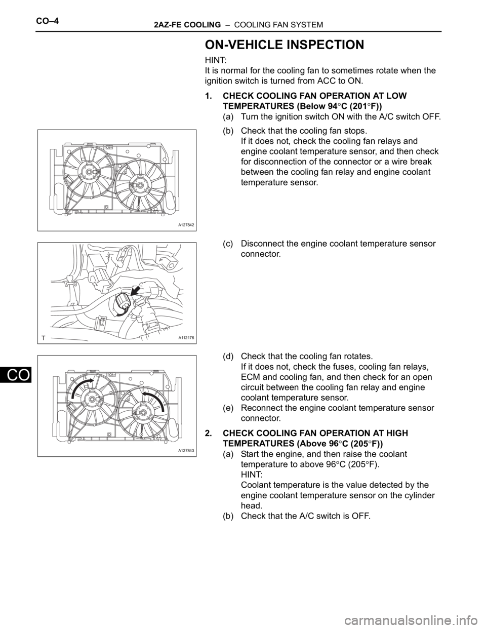
(a) Turn the ignition switch ON with the A/C switch OFF.
(b) Check that the cooling fan stops.
If it does not, check the cooling fan relays and
engine coolant temperature sensor, and then check
for disconnection of the connector or a wire break
between the cooling fan relay and engine coolant
temperature sensor.
(c) Disconnect the engine coolant temperature sensor
connector.
(d) Check that the cooling fan rotates.
If it does not, check the fuses, cooling fan relays,
ECM and cooling fan, and then check for an open
circuit between the cooling fan relay and engine
coolant temperature sensor.
(e) Reconnect the engine coolant temperature sensor
connector.
2. CHECK COOLING FAN OPERATION AT HIGH
TEMPERATURES (Above 96
C (205F))
(a) Start the engine, and then raise the coolant
temperature to above 96
C (205F).
HINT:
Coolant temperature is the value detected by the
engine coolant temperature sensor on the cylinder
head.
(b) Check that the A/C switch is OFF.
A127842
A112176
A127843
Page 253 of 2000
2AZ-FE IGNITION – IGNITION SYSTEMIG–3
IG
SYSTEM DIAGRAM
A126882E02
Page 254 of 2000
IG–42AZ-FE IGNITION – IGNITION SYSTEM
IG
A126768E01