Page 543 of 2000
2GR-FE ENGINE CONTROL SYSTEM – SFI SYSTEMES–19
ES
3. READ VIN
(a) Confirm the vehicle VIN.
(b) Connect the intelligent tester to the DLC3.
(c) Turn the ignition switch ON.
(d) Turn the tester ON.
(e) Select the following menu items: DIAGNOSIS /
ENHANCED OBD II / VIN.
4. WRITE VIN
(a) Confirm the vehicle VIN.
(b) Connect the intelligent tester to the DLC3.
(c) Turn the ignition switch ON.
(d) Turn the tester ON.
A103812E08
Page 547 of 2000

2GR-FE ENGINE CONTROL SYSTEM – SFI SYSTEMES–23
ES
CHECKING MONITOR STATUS
The purpose of the monitor result (mode 06) is to allow
access to the results of on-board diagnostic monitoring tests
of specific components/systems that are not continuously
monitored. Examples are catalysts, evaporative emissions
(EVAP) and thermostats.
The monitor result allows the OBD II scan tool to display the
monitor status, test value, minimum test limit and maximum
test limit. These data are displayed after the vehicle has been
driven to run the monitor.
When the test value is not between the minimum and
maximum test limits, the ECM (PCM) interprets this as a
malfunction. If the test value is on the borderline of the test
limits, the component is likely to malfunction in the near
future.
Perform the following procedures to view the monitor status.
Although these procedures refer to the Lexus/Toyota
diagnostic tester, the monitor status can be checked using a
generic OBD II scan tool. Refer to your scan tool operator's
manual for specific procedural information.
1. PERFORM MONITOR DRIVE PATTERN
(a) Connect the intelligent tester to the DLC3.
(b) Turn the ignition switch and the tester ON.
(c) Clear the DTCs (see page ES-39).
(d) Run the vehicle in accordance with the applicable
drive pattern described in READINESS MONITOR
DRIVE PATTERN (see page ES-22). Do not turn the
ignition switch OFF.
NOTE:
The test results will be lost if the ignition
switch is turned OFF.
2. ACCESS MONITOR RESULT
(a) Select the following items from the intelligent tester
menus: DIAGNOSIS, ENHANCED OBD II,
MONITOR INFO and MONITOR RESULT. The
monitor status appears after the component name.
• INCMP: The component has not been monitored
yet.
• PASS: The component is functioning normally.
• FAIL: The component is malfunctioning.
(b) Confirm that the component is either PASS or FAIL.
(c) Select the component and press ENTER. The
accuracy test value appears if the monitor status is
either PASS or FAIL.
3. CHECK COMPONENT STATUS
(a) Compare the test value with the minimum test limit
(MIN LIMIT) and maximum test limit (MAX LIMIT).
Page 549 of 2000

2GR-FE ENGINE CONTROL SYSTEM – SFI SYSTEMES–25
ES
Rear Oxygen Sensor Heater
Misfire
$3D $D1 Multiply by 0.001 kPa Test value for reference orifice high flow (P043F)
$3D $D4 Multiply by 0.001 kPa Test value for purge VSV stuck closed (P0441)
$3D $D5 Multiply by 0.001 kPa Test value for purge VSV stuck open (P0441)
$3D $D7 Multiply by 0.001 kPa Test value for purge flow insufficient (P0441)
Monitor ID Test ID Scaling Unit Description
$42 $91 Multiply by 0.001 Ohm Oxygen sensor heater resistance bank 1 sensor 2
$46 $91 Multiply by 0.001 Ohm Oxygen sensor heater resistance bank 2 sensor 2
Monitor ID Test ID Scaling Unit Description
$A1 $0B Multiply by 1 TimeExponential Weighted Moving Average (EWMA) misfire for all
cylinders:
EWMA = Total misfire counts for last driving cycle * 0.1 + Last
EWMA * 0.9
Misfire counts for last 10 driving cycles - Total
$A1 $0C Multiply by 1 TimeIgnition switch ON: Total misfire counts for last driving cycle
Engine running: Total misfire counts for current driving cycle
Misfire counts for last or current driving cycle - all cylinders
$A2 $0B Multiply by 1 TimeExponential Weighted Moving Average (EWMA) misfire for
cylinder 1:
EWMA = Total misfire counts for last driving cycle * 0.1 + Last
EWMA * 0.9
Misfire counts for last 10 driving cycles - Total
$A2 $0C Multiply by 1 TimeIgnition switch ON: Total misfire counts for last driving cycle
Engine running: Total misfire counts for current driving cycle
Misfire counts for last or current driving cycle - cylinder 1
$A3 $0B Multiply by 1 TimeExponential Weighted Moving Average (EWMA) misfire for
cylinder 2:
EWMA = Total misfire counts for last driving cycle * 0.1 + Last
EWMA * 0.9
Misfire counts for last 10 driving cycles - Total
$A3 $0C Multiply by 1 TimeIgnition switch ON: Total misfire counts for last driving cycle
Engine running: Total misfire counts for current driving cycle
Misfire counts for last or current driving cycle - cylinder 2
$A4 $0B Multiply by 1 TimeExponential Weighted Moving Average (EWMA) misfire for
cylinder 3:
EWMA = Total misfire counts for last driving cycle * 0.1 + Last
EWMA * 0.9
Misfire counts for last 10 driving cycles - Total
$A4 $0C Multiply by 1 TimeIgnition switch ON: Total misfire counts for last driving cycle
Engine running: Total misfire counts for current driving cycle
Misfire counts for last or current driving cycle - cylinder 3
$A5 $0B Multiply by 1 TimeExponential Weighted Moving Average (EWMA) misfire for
cylinder 4:
EWMA = Total misfire counts for last driving cycle * 0.1 + Last
EWMA * 0.9
Misfire counts for last 10 driving cycles - Total
$A5 $0C Multiply by 1 TimeIgnition switch ON: Total misfire counts for last driving cycle
Engine running: Total misfire counts for current driving cycle
Misfire counts for last or current driving cycle - cylinder 4
$A6 $0B Multiply by 1 TimeExponential Weighted Moving Average (EWMA) misfire for
cylinder 5:
EWMA = Total misfire counts for last driving cycle * 0.1 + Last
EWMA * 0.9
Misfire counts for last 10 driving cycles - Total
$A6 $0C Multiply by 1 TimeIgnition switch ON: Total misfire counts for last driving cycle
Engine running: Total misfire counts for current driving cycle
Misfire counts for last or current driving cycle - cylinder 5 Monitor ID Test ID Scaling Unit Description
Page 550 of 2000
ES–262GR-FE ENGINE CONTROL SYSTEM – SFI SYSTEM
ES
$A7 $0B Multiply by 1 TimeExponential Weighted Moving Average (EWMA) misfire for
cylinder 6:
EWMA = Total misfire counts for last driving cycle * 0.1 + Last
EWMA * 0.9
Misfire counts for last 10 driving cycles - Total
$A7 $0C Multiply by 1 TimeIgnition switch ON: Total misfire counts for last driving cycle
Engine running: Total misfire counts for current driving cycle
Misfire counts for last or current driving cycle - cylinder 6 Monitor ID Test ID Scaling Unit Description
Page 552 of 2000

ES–282GR-FE ENGINE CONTROL SYSTEM – SFI SYSTEM
ES
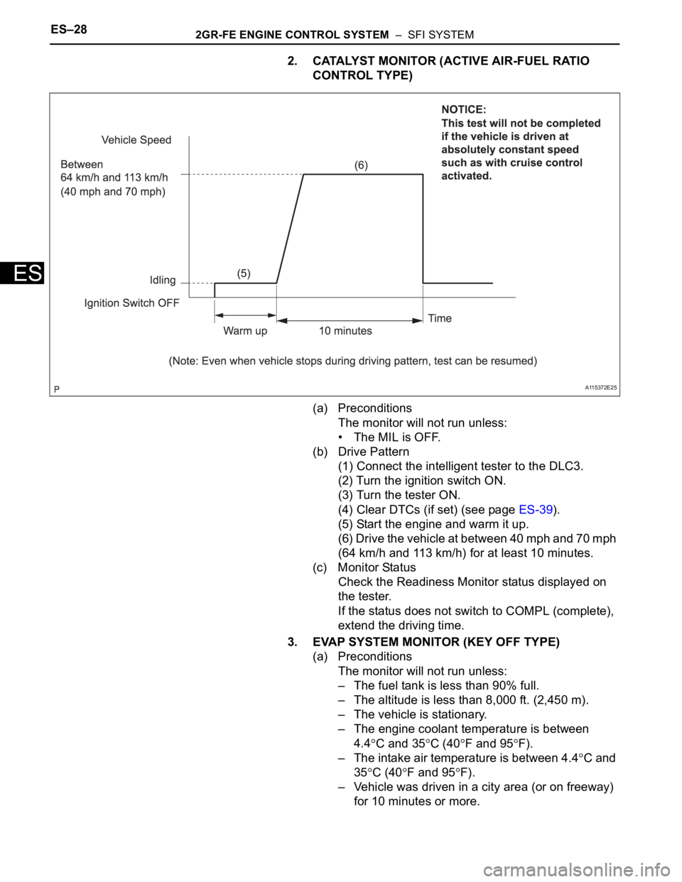
2. CATALYST MONITOR (ACTIVE AIR-FUEL RATIO
CONTROL TYPE)
(a) Preconditions
The monitor will not run unless:
• The MIL is OFF.
(b) Drive Pattern
(1) Connect the intelligent tester to the DLC3.
(2) Turn the ignition switch ON.
(3) Turn the tester ON.
(4) Clear DTCs (if set) (see page ES-39).
(5) Start the engine and warm it up.
(6) Drive the vehicle at between 40 mph and 70 mph
(64 km/h and 113 km/h) for at least 10 minutes.
(c) Monitor Status
Check the Readiness Monitor status displayed on
the tester.
If the status does not switch to COMPL (complete),
extend the driving time.
3. EVAP SYSTEM MONITOR (KEY OFF TYPE)
(a) Preconditions
The monitor will not run unless:
– The fuel tank is less than 90% full.
– The altitude is less than 8,000 ft. (2,450 m).
– The vehicle is stationary.
– The engine coolant temperature is between
4.4
C and 35C (40F and 95F).
– The intake air temperature is between 4.4
C and
35
C (40F and 95F).
– Vehicle was driven in a city area (or on freeway)
for 10 minutes or more.
A115372E25
Page 553 of 2000

2GR-FE ENGINE CONTROL SYSTEM – SFI SYSTEMES–29
ES
(b) Monitor Conditions
(1) Turn the ignition switch OFF and wait for 6
hours.
HINT:
Do not start the engine until checking Readiness
Monitor status. If the engine is started, the step
described above must be repeated.
(c) Monitor Status
(1) Connect the intelligent tester to the DLC3.
(2) Turn the ignition switch ON.
(3) Turn the tester ON.
(4) Check the Readiness Monitor status displayed
on the tester.
If the status does not switch to COMPL (complete), restart the
engine, make sure that the preconditions have been met, and
then perform the Monitor Conditions again.
4. AIR-FUEL RATIO (A/F) AND HEATED OXYGEN (HO2)
SENSOR MONITORS (ACTIVE AIR-FUEL RATIO
CONTROL TYPE)
(a) Preconditions
The monitor will not run unless:
– 2 minutes or more have elapsed since the engine
was started.
– The Engine Coolant Temperature (ECT) is 75
C
(167
F) or more.
– Cumulative driving time at a vehicle speed of 48
km/h (30 mph) or more exceeds 6 minutes.
A115374E08
Page 554 of 2000

ES–302GR-FE ENGINE CONTROL SYSTEM – SFI SYSTEM
ES
– Air-fuel ratio feedback control is performed.
(b) Drive Pattern for front A/F sensor and HO2 sensor
(1) Connect the intelligent tester to the DLC3.
(2) Turn the ignition switch ON.
(3) Turn the tester ON.
(4) Clear DTCs (see page ES-39).
(5) Start the engine, and warm it up until the ECT
reaches 75
C (167F) or higher.
(6) Drive the vehicle at between 60 km/h (38 mph)
and 120 km/h (75 mph) for at least 10 minutes.
(7) Change the transmission to 2nd gear.
(8) Accelerate the vehicle to 64 km/h (40 mph) or
more by depressing the accelerator pedal for at
least 10 seconds.
(9) Soon after performing step (8) above, release
the accelerator pedal for at least 4 seconds without
depressing the brake pedal in order to execute fuel-
cut control.
(10) Allow the vehicle to decelerate until the vehicle
speed declines to less than 10 km/h (6 mph).
(11) Repeat steps from (8) through (10) above at
least 3 times in one driving cycle.
(c) Monitor Status
(1) Check the Readiness Monitor status displayed
on the tester.
(2) If the status does not switch to COMPL
(complete), make sure that the preconditions
have been met, and then perform steps from (5)
through (11) in the Drive Pattern above.
5. AIR-FUEL RATIO (A/F) AND HEATED OXYGEN (HO2)
SENSOR HEATER MONITORS (FRONT A/F AND
REAR HO2 SENSOR TYPE)
A121604E06
Page 555 of 2000
2GR-FE ENGINE CONTROL SYSTEM – SFI SYSTEMES–31
ES
(a) Preconditions
The monitor will not run unless:
– The MIL is OFF.
(b) Drive Pattern
(1) Connect the intelligent tester to the DLC3.
(2) Turn the ignition switch ON.
(3) Turn the tester ON.
(4) Clear DTCs (if set) (see page ES-39).
(5) Start the engine.
(6) Allow the engine to idle for 10 minutes or more.
(7) Drive the vehicle at 40 km/h (25 mph) or more
for at least 2 minutes.
(c) Monitor Status
(1) Check the Readiness Monitor status displayed
on the tester.
If the status does not switch to COMPL
(complete), make sure that the preconditions
have been met, and repeat steps from (5) to (7)
described in the Drive Pattern above.