Page 603 of 2000

2AZ-FE ENGINE MECHANICAL – CYLINDER HEADEM–59
EM
23. DISCONNECT ENGINE WIRE
(a) Disconnect the radio setting condenser connector.
(b) Disconnect the engine oil pressure switch
connector.
(c) Disconnect the engine coolant temperature sensor
connector.
(d) Disconnect the camshaft position sensor connector.
(e) Remove the bolt and ground cable.
24. REMOVE FRONT SUSPENSION MEMBER
REINFORCEMENT RH (See page EM-6)
25. REMOVE FAN AND GENERATOR V BELT (See page
EM-6)
26. REMOVE GENERATOR ASSEMBLY (See page CH-9)
27. REMOVE ENGINE MOUNTING INSULATOR RH (See
page EM-22)
28. REMOVE IDLER PULLEY (See page EM-23)
29. REMOVE IGNITION COIL ASSEMBLY (See page IG-9)
30. REMOVE SPARK PLUG (See page EM-8)
31. REMOVE CYLINDER HEAD COVER SUB-ASSEMBLY
(See page EM-24)
32. REMOVE V-RIBBED BELT TENSIONER ASSEMBLY
(See page EM-26)
33. REMOVE CRANKSHAFT POSITION SENSOR (See
page ES-402)
34. REMOVE OIL PAN SUB-ASSEMBLY (See page EM-
24)
35. SET NO. 1 CYLINDER TO TDC/COMPRESSION
(a) Turn the crankshaft pulley until its groove and the
timing mark "0" of the timing chain cover are
aligned.
(b) Check that each timing mark of the camshaft timing
gear and sprocket is aligned with each timing mark
located on the No. 1 and No. 2 bearing caps as
shown in the illustration.
If not, turn the crankshaft by 1 revolution (360
) to
align the timing marks as above.
A098748E01
A098345E09
Page 629 of 2000

2AZ-FE ENGINE MECHANICAL – CYLINDER HEADEM–85
EM
(c) Examine the front marks and numbers, and check
that the order is as shown in the illustration. Then
install the bearing caps onto the cylinder head.
(d) Apply a light coat of engine oil to the threads and
under the heads of the bearing cap bolts.
(e) Using several steps, uniformly tighten the 20
bearing cap bolts in the sequence shown in the
illustration.
Torque: 29.5 N*m (301 kgf*cm, 22 ft.*lbf) for No.
1 and No. 2 bearing cap
9.0 N*m (92 kgf*cm, 80 in.*lbf) for No. 3
bearing cap
NOTICE:
Install the camshaft with the timing mark of the
camshaft timing gear on top.
6. INSTALL NO. 1 CHAIN VIBRATION DAMPER (See
page EM-33)
7. INSTALL CHAIN SUB-ASSEMBLY (See page EM-33)
8. INSTALL CHAIN TENSIONER SLIPPER (See page
EM-34)
9. INSTALL TIMING CHAIN GUIDE (See page EM-34)
10. INSTALL NO. 1 CRANKSHAFT POSITION SENSOR
PLATE (See page EM-35)
11. INSTALL TIMING CHAIN COVER SUB-ASSEMBLY
(See page EM-35)
12. INSTALL NO. 1 CHAIN TENSIONER ASSEMBLY (See
page EM-37)
13. INSTALL V-RIBBED BELT TENSIONER ASSEMBLY
(See page EM-38)
14. INSTALL ENGINE MOUNTING BRACKET RH (See
page EM-38)
15. INSTALL CRANKSHAFT PULLEY (See page EM-38)
16. INSTALL OIL PAN SUB-ASSEMBLY (See page EM-39)
17. INSTALL CRANKSHAFT POSITION SENSOR (See
page ES-402)
18. INSTALL CYLINDER HEAD COVER SUB-ASSEMBLY
(See page EM-40)
19. INSTALL SPARK PLUG (See page EM-16)
20. INSTALL IGNITION COIL ASSEMBLY (See page IG-9)
21. INSTALL IDLER PULLEY (See page EM-41)
F050591E01
F050596E02
Page 632 of 2000
EM–882AZ-FE ENGINE MECHANICAL – CYLINDER HEAD
EM
47. CHECK FOR ENGINE OIL LEAKS
48. CHECK FOR EXHAUST GAS LEAKS
49. INSPECT IGNITION TIMING (See page EM-1)
50. INSPECT ENGINE IDLING SPEED (See page EM-2)
51. INSPECT COMPRESSION (See page EM-3)
52. INSPECT CO/HC (See page EM-4)
53. INSTALL NO. 1 ENGINE COVER (See page EM-43)
54. INSTALL FRONT FENDER APRON RH
55. INSTALL NO. 1 ENGINE UNDER COVER
56. INSTALL FRONT WHEEL RH
57. INSTALL RADIATOR SUPPORT OPENING COVER
REPAIR
1. REPAIR VALVE SEATS
(a) If the seating is too high on the valve face, use 30
and 45
cutters to correct the seat.
(b) If the seating is too low on the valve face, use 75
and 45
cutters to correct the seat.
Standard width
(c) Lap the valve and valve seat by hand with an
abrasive compound.
(d) Recheck the valve seating position.
A128227E01
Item Standard Condition
Intake 1.0 to 1.4 mm (0.0394 to 0.0551 in.)
Exhaust 1.2 to 1.6 mm (0.0427 to 0.0630 in.)
Page 650 of 2000

2AZ-FE ENGINE MECHANICAL – ENGINE UNITEM–123
EM
DISASSEMBLY
1. REMOVE IDLER PULLEY (See page EM-23)
2. REMOVE OIL DIPSTICK
3. REMOVE OIL DIPSTICK GUIDE (See page EM-57)
4. REMOVE MANIFOLD STAY (See page EM-57)
5. REMOVE NO. 2 MANIFOLD STAY (See page EM-58)
6. REMOVE NO. 1 EXHAUST MANIFOLD HEAT
INSULATOR (See page EM-58)
7. REMOVE EXHAUST MANIFOLD CONVERTER SUB-
ASSEMBLY (See page EM-58)
8. REMOVE WATER INLET (See page CO-15)
9. REMOVE THERMOSTAT
10. REMOVE NO. 1 WATER BY-PASS PIPE
(a) Remove the bolt, 2 nuts, pipe and gasket.
11. REMOVE NO. 3 WATER BY-PASS PIPE
(a) Remove the bolt, 2 nuts, pipe and gasket.
12. REMOVE V-RIBBED BELT TENSIONER ASSEMBLY
(See page EM-26)
13. REMOVE CAMSHAFT TIMING OIL CONTROL VALVE
ASSEMBLY (See page ES-395)
14. REMOVE KNOCK SENSOR (See page ES-420)
15. REMOVE RADIO SETTING CONDENSER (See page
EM-63)
16. REMOVE OIL PRESSURE SWITCH ASSEMBLY (See
page EM-63)
17. REMOVE ENGINE COOLANT TEMPERATURE
SENSOR (See page EM-63)
18. REMOVE CAMSHAFT POSITION SENSOR (See page
EM-64)
19. REMOVE IGNITION COIL ASSEMBLY (See page IG-9)
A112226
A126940
Page 680 of 2000

EM–342GR-FE ENGINE MECHANICAL – ENGINE ASSEMBLY
EM
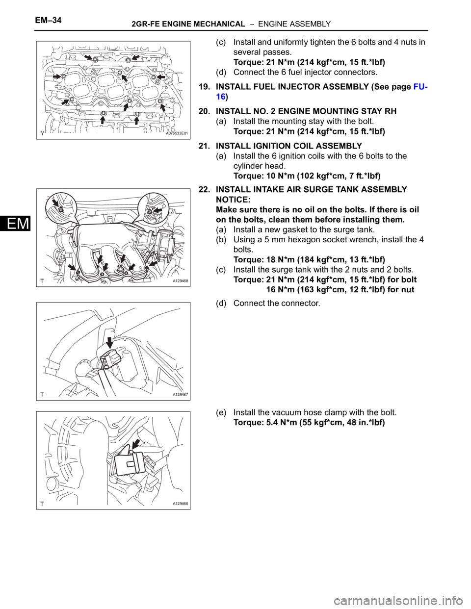
(c) Install and uniformly tighten the 6 bolts and 4 nuts in
several passes.
Torque: 21 N*m (214 kgf*cm, 15 ft.*lbf)
(d) Connect the 6 fuel injector connectors.
19. INSTALL FUEL INJECTOR ASSEMBLY (See page FU-
16)
20. INSTALL NO. 2 ENGINE MOUNTING STAY RH
(a) Install the mounting stay with the bolt.
Torque: 21 N*m (214 kgf*cm, 15 ft.*lbf)
21. INSTALL IGNITION COIL ASSEMBLY
(a) Install the 6 ignition coils with the 6 bolts to the
cylinder head.
Torque: 10 N*m (102 kgf*cm, 7 ft.*lbf)
22. INSTALL INTAKE AIR SURGE TANK ASSEMBLY
NOTICE:
Make sure there is no oil on the bolts. If there is oil
on the bolts, clean them before installing them.
(a) Install a new gasket to the surge tank.
(b) Using a 5 mm hexagon socket wrench, install the 4
bolts.
Torque: 18 N*m (184 kgf*cm, 13 ft.*lbf)
(c) Install the surge tank with the 2 nuts and 2 bolts.
Torque: 21 N*m (214 kgf*cm, 15 ft.*lbf) for bolt
16 N*m (163 kgf*cm, 12 ft.*lbf) for nut
(d) Connect the connector.
(e) Install the vacuum hose clamp with the bolt.
Torque: 5.4 N*m (55 kgf*cm, 48 in.*lbf)
A076533E01
A129468
A129467
A129466
Page 769 of 2000

2AZ-FE FUEL – FUEL INJECTORFU–9
FU
REMOVAL
1. DISCHARGE FUEL SYSTEM PRESSURE
CAUTION:
• DISCHARGE FUEL SYSTEM PRESSURE
procedures must be performed before
disconnecting any part of the fuel system.
• After performing the DISCHARGE FUEL SYSTEM
PRESSURE procedures, pressure will remain in
the fuel line. When disconnecting the fuel line,
place a cloth or equivalent over fittings to reduce
the risk of fuel spray.
(a) Remove the console box (see page IR-83).
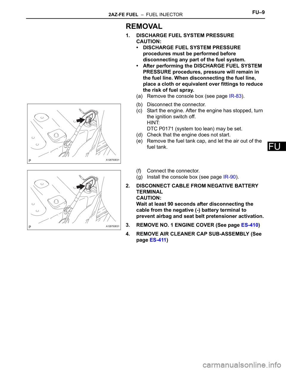
(b) Disconnect the connector.
(c) Start the engine. After the engine has stopped, turn
the ignition switch off.
HINT:
DTC P0171 (system too lean) may be set.
(d) Check that the engine does not start.
(e) Remove the fuel tank cap, and let the air out of the
fuel tank.
(f) Connect the connector.
(g) Install the console box (see page IR-90).
2. DISCONNECT CABLE FROM NEGATIVE BATTERY
TERMINAL
CAUTION:
Wait at least 90 seconds after disconnecting the
cable from the negative (-) battery terminal to
prevent airbag and seat belt pretensioner activation.
3. REMOVE NO. 1 ENGINE COVER (See page ES-410)
4. REMOVE AIR CLEANER CAP SUB-ASSEMBLY (See
page ES-411)
A128750E01
A128750E01
Page 772 of 2000

FU–122AZ-FE FUEL – FUEL INJECTOR
FU
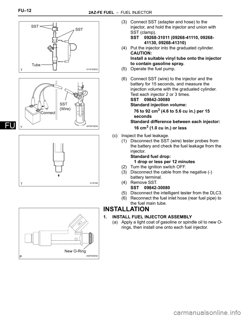
(3) Connect SST (adapter and hose) to the
injector, and hold the injector and union with
SST (clamp).
SST 09268-31011 (09268-41110, 09268-
41130, 09268-41310)
(4) Put the injector into the graduated cylinder.
CAUTION:
Install a suitable vinyl tube onto the injector
to contain gasoline spray.
(5) Operate the fuel pump.
(6) Connect SST (wire) to the injector and the
battery for 15 seconds, and measure the
injection volume with the graduated cylinder.
Test each injector 2 or 3 times.
SST 09842-30080
Standard injection volume:
76 to 92 cm
3 (4.6 to 5.6 cu in.) per 15
seconds
Standard difference between each injector:
16 cm
3 (1.0 cu in.) or less
(c) Inspect the fuel leakage.
(1) Disconnect the SST (wire) tester probes from
the battery and check the fuel leakage from the
injector.
Standard fuel drop:
1 drop or less per 12 minutes
(2) Turn the ignition switch OFF.
(3) Disconnect the cable from the negative (-)
battery terminal.
(4) Remove SST.
SST 09842-30080
(5) Disconnect the intelligent tester from the DLC3.
(6) Reconnect the fuel inlet hose (rear fuel pipe) to
the fuel main tube.
INSTALLATION
1. INSTALL FUEL INJECTOR ASSEMBLY
(a) Apply a light coat of gasoline or spindle oil to new O-
rings, then install one onto each fuel injector.
A116183E02
A075915E04
A116184
A097400E02
Page 774 of 2000

FU–142AZ-FE FUEL – FUEL INJECTOR
FU
(f) Connect the 4 fuel injector connectors.
(g) Install the 2 wire harness clamps.
3. CONNECT NO. 2 VENTILATION HOSE
(a) Connect the ventilation hose to the ventilation valve.
NOTICE:
Make sure that the paint mark and hose clamp
are at the correct angle when installing the hose.
4. CONNECT FUEL MAIN TUBE
(a) Connect the fuel main tube.
(b) Push the fuel tube connector until it makes a "click"
sound.
(c) Install the fuel pipe clamp.
(d) Install the fuel tube to the fuel hose clamp.
5. INSTALL AIR CLEANER CAP SUB-ASSEMBLY (See
page ES-413)
6. INSTALL NO. 1 ENGINE COVER (See page ES-414)
7. CONNECT CABLE TO BATTERY NEGATIVE
TERMINAL
8. CHECK FOR FUEL LEAKAGE
(a) Make sure that there are no fuel leaks after
performing maintenance on the fuel system.
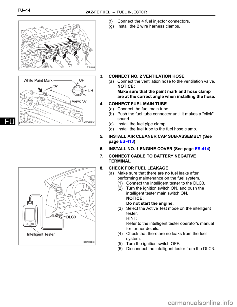
(1) Connect the intelligent tester to the DLC3.
(2) Turn the ignition switch ON, and push the
intelligent tester main switch ON.
NOTICE:
Do not start the engine.
(3) Select the Active Test mode on the intelligent
tester.
HINT:
Refer to the intelligent tester operator's manual
for further details.
(4) Check that there are no leaks from the fuel
system.
(5) Turn the ignition switch OFF.
(6) Disconnect the intelligent tester from the DLC3.
A125333
A095428E02
B127990E01