Page 1274 of 2000
AX–170U241E AUTOMATIC TRANSAXLE – AUTOMATIC TRANSAXLE UNIT
AX
20. REMOVE B-3 ACCUMULATOR PISTON
(a) Apply compressed air (392 kPa, 4.0 kgf/cm
2, 57 psi)
to the oil hole and remove the B-3 accumulator
piston and 2 compression springs.
NOTICE:
• Applying compressed air may cause the
piston to jump out. When removing the
piston, hold it with your hand using a waste
cloth.
• Make sure not to spatter ATF when applying
compressed air.
(b) Remove the O-ring from the B-3 accumulator
piston.
21. REMOVE MANUAL DETENT SPRING SUB-
ASSEMBLY
(a) Remove the 2 bolts, manual detent spring and
cover.
22. REMOVE PARKING LOCK PAWL BRACKET
(a) Remove the 2 bolts and parking lock pawl bracket.
23. REMOVE MANUAL VALVE LEVER SHAFT RETAINER
SPRING
(a) Using needle-nose pliers, remove the retainer
spring.
D003558E02
D003904E05
D003560E03
C056727E01
D003559E01
Page 1287 of 2000

U241E AUTOMATIC TRANSAXLE – AUTOMATIC TRANSAXLE UNITAX–183
AX
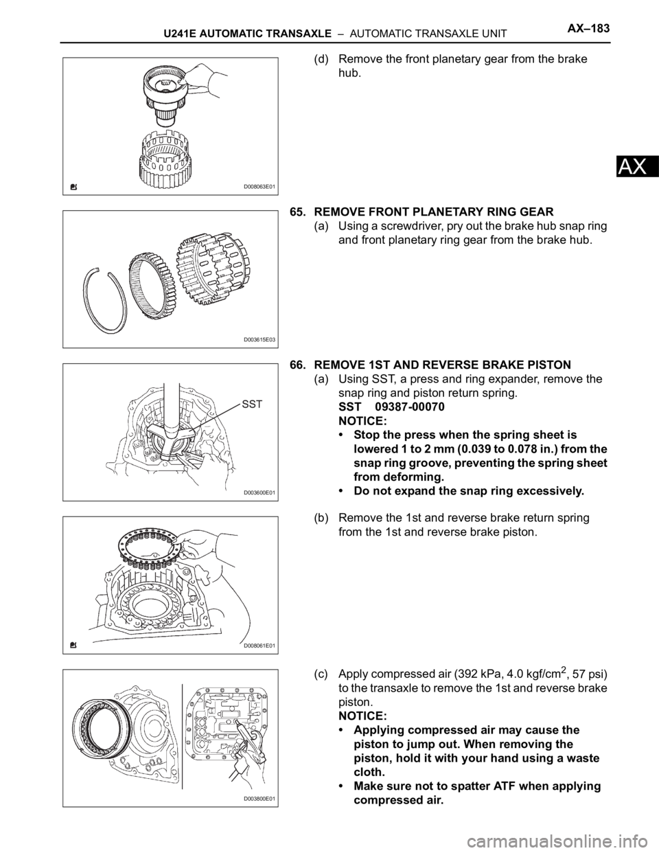
(d) Remove the front planetary gear from the brake
hub.
65. REMOVE FRONT PLANETARY RING GEAR
(a) Using a screwdriver, pry out the brake hub snap ring
and front planetary ring gear from the brake hub.
66. REMOVE 1ST AND REVERSE BRAKE PISTON
(a) Using SST, a press and ring expander, remove the
snap ring and piston return spring.
SST 09387-00070
NOTICE:
• Stop the press when the spring sheet is
lowered 1 to 2 mm (0.039 to 0.078 in.) from the
snap ring groove, preventing the spring sheet
from deforming.
• Do not expand the snap ring excessively.
(b) Remove the 1st and reverse brake return spring
from the 1st and reverse brake piston.
(c) Apply compressed air (392 kPa, 4.0 kgf/cm
2, 57 psi)
to the transaxle to remove the 1st and reverse brake
piston.
NOTICE:
• Applying compressed air may cause the
piston to jump out. When removing the
piston, hold it with your hand using a waste
cloth.
• Make sure not to spatter ATF when applying
compressed air.
D008063E01
D003615E03
D003600E01
D008061E01
D003800E01
Page 1290 of 2000

AX–186U241E AUTOMATIC TRANSAXLE – AUTOMATIC TRANSAXLE UNIT
AX
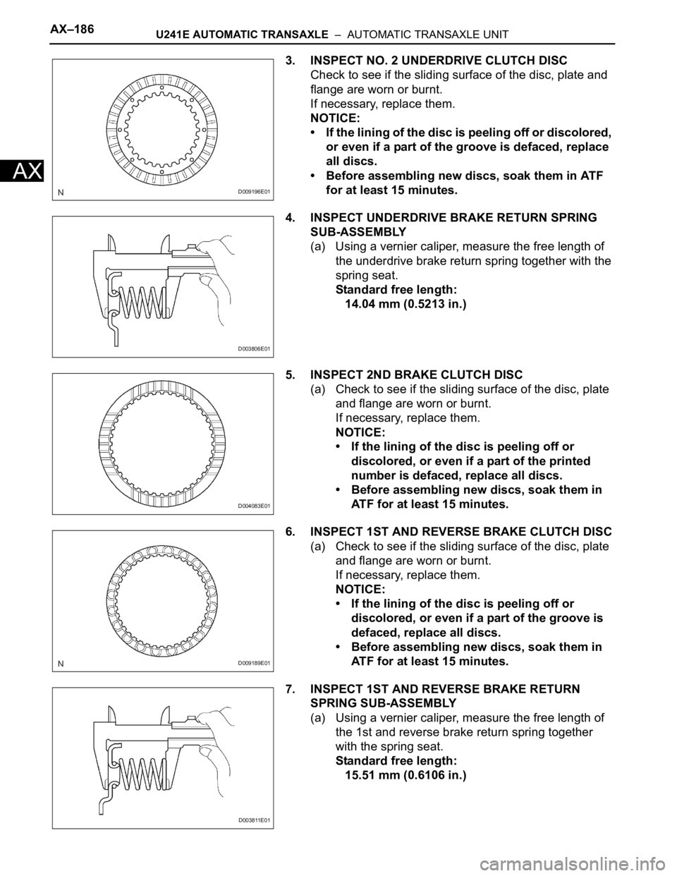
3. INSPECT NO. 2 UNDERDRIVE CLUTCH DISC
Check to see if the sliding surface of the disc, plate and
flange are worn or burnt.
If necessary, replace them.
NOTICE:
• If the lining of the disc is peeling off or discolored,
or even if a part of the groove is defaced, replace
all discs.
• Before assembling new discs, soak them in ATF
for at least 15 minutes.
4. INSPECT UNDERDRIVE BRAKE RETURN SPRING
SUB-ASSEMBLY
(a) Using a vernier caliper, measure the free length of
the underdrive brake return spring together with the
spring seat.
Standard free length:
14.04 mm (0.5213 in.)
5. INSPECT 2ND BRAKE CLUTCH DISC
(a) Check to see if the sliding surface of the disc, plate
and flange are worn or burnt.
If necessary, replace them.
NOTICE:
• If the lining of the disc is peeling off or
discolored, or even if a part of the printed
number is defaced, replace all discs.
• Before assembling new discs, soak them in
ATF for at least 15 minutes.
6. INSPECT 1ST AND REVERSE BRAKE CLUTCH DISC
(a) Check to see if the sliding surface of the disc, plate
and flange are worn or burnt.
If necessary, replace them.
NOTICE:
• If the lining of the disc is peeling off or
discolored, or even if a part of the groove is
defaced, replace all discs.
• Before assembling new discs, soak them in
ATF for at least 15 minutes.
7. INSPECT 1ST AND REVERSE BRAKE RETURN
SPRING SUB-ASSEMBLY
(a) Using a vernier caliper, measure the free length of
the 1st and reverse brake return spring together
with the spring seat.
Standard free length:
15.51 mm (0.6106 in.)
D009196E01
D003806E01
D004083E01
D009189E01
D003811E01
Page 1294 of 2000
AX–190U241E AUTOMATIC TRANSAXLE – AUTOMATIC TRANSAXLE UNIT
AX
5. INSTALL COUNTER DRIVE GEAR
(a) Using SST and a press, press in the 2 counter drive
gear bearings outer races to the transaxle.
NOTICE:
• Press-fit the bearing race until it contacts the
snap ring.
• Do not apply excessive pressure.
SST 09950-60020 (09951-00890, 09951-07150)
(b) Using SST and a press, press in the tapered roller
bearing to the counter drive gear.
SST 09649-17010
NOTICE:
• Press-fit the bearing inner race until it
contacts the counter drive gear.
• Do not apply excessive pressure.
(c) Using SST and a press, press in the counter drive
gear and bearing to the transaxle.
SST 09950-60020 (09951-00890), 09950-70010
(09951-07150)
NOTICE:
Do not apply excessive pressure.
6. INSTALL 1ST AND REVERSE BRAKE PISTON
(a) Coat 2 new O-rings with ATF.
(b) Install the 2 O-ring to the 1st and reverse brake
piston.
D003611E04
D003613E01
D003614E01
D003913E01
Page 1295 of 2000
U241E AUTOMATIC TRANSAXLE – AUTOMATIC TRANSAXLE UNITAX–191
AX
(c) Coat the 1st and reverse brake piston with ATF, and
install it to the transaxle.
(d) Install the 1st and reverse brake return spring to the
1st and reverse brake piston.
(e) Using SST, a press and snap ring expander, press
the piston return spring and snap ring to the
transaxle.
NOTICE:
• Stop the press when the spring sheet is
lowered to the place 1 to 2 mm (0.039 to 0.078
in.) from the snap ring groove, preventing the
spring sheet from being deform.
• Do not expand the snap ring excessively.
7. INSTALL FRONT PLANETARY RING GEAR
(a) Using a screwdriver, install the front planetary ring
gear and brake hub snap ring to the brake hub.
8. INSTALL FRONT PLANETARY GEAR ASSEMBLY
(a) Install the front planetary gear to the brake hub.
D003813E01
D008072E01
D003600E01
D003615E03
D008063E01
Page 1297 of 2000
U241E AUTOMATIC TRANSAXLE – AUTOMATIC TRANSAXLE UNITAX–193
AX
Torque: Turning torque at 60 rpm
0.5 to 1.0 N*m (5.1 to 10.0 kgf*cm, 4.4 to
8.7 in.*lbf) for new
0.3 to 0.5 N*m (3.1 to 5.1 kgf*cm, 2.7 to
4.4 in.*lbf) for used
(f) Using a chisel and hammer, stake the front
planetary gear washer.
9. INSTALL INPUT SUN GEAR
(a) Install the 2 thrust bearings, bearing race and front
planetary sun gear to the planetary gear.
Standard bearing race diameter
10. INSTALL REAR PLANETARY GEAR ASSEMBLY
(a) Coat the bearing race with ATF, and install it to the
rear planetary gear.
Standard bearing race diameter
(b) Install the planetary carrier thrust washer to the
planetary gear.
D008074E02
D003873E03
Item Inside Outside
Bearing 34.6 mm (1.362 in.) 52.2 mm (2.055 in.)
Race 40.3 mm (1.587 in.) 58.0 mm (2.283 in.)
Bearing 38.6 mm (1.520 in.) 60.0 mm (2.362 in.)
D003593E01
Item Inside Outside
Race 38.6 mm (1.520 in.) 58.0 mm (2.283 in.)
D003910E01
Page 1304 of 2000

AX–200U241E AUTOMATIC TRANSAXLE – AUTOMATIC TRANSAXLE UNIT
AX
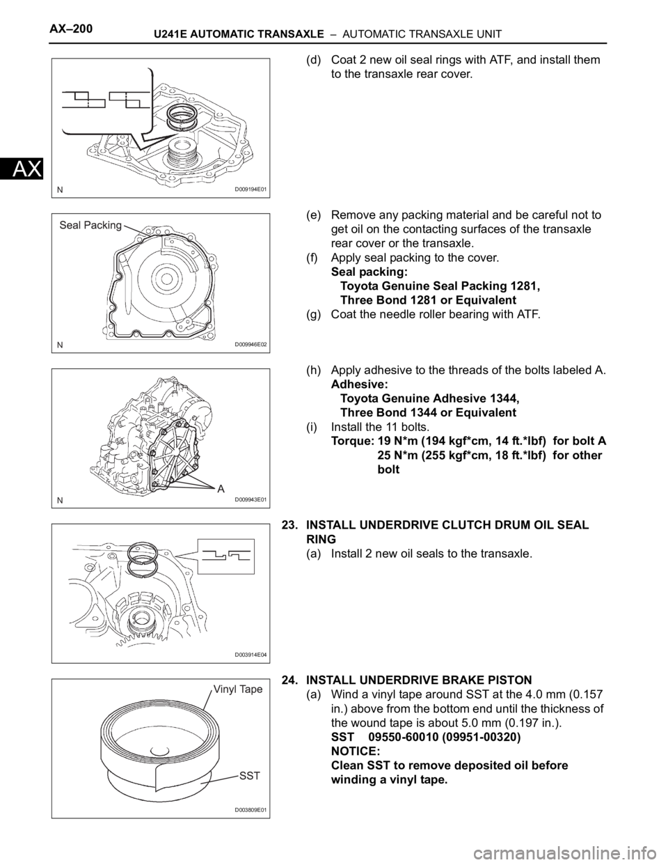
(d) Coat 2 new oil seal rings with ATF, and install them
to the transaxle rear cover.
(e) Remove any packing material and be careful not to
get oil on the contacting surfaces of the transaxle
rear cover or the transaxle.
(f) Apply seal packing to the cover.
Seal packing:
Toyota Genuine Seal Packing 1281,
Three Bond 1281 or Equivalent
(g) Coat the needle roller bearing with ATF.
(h) Apply adhesive to the threads of the bolts labeled A.
Adhesive:
Toyota Genuine Adhesive 1344,
Three Bond 1344 or Equivalent
(i) Install the 11 bolts.
Torque: 19 N*m (194 kgf*cm, 14 ft.*lbf) for bolt A
25 N*m (255 kgf*cm, 18 ft.*lbf) for other
bolt
23. INSTALL UNDERDRIVE CLUTCH DRUM OIL SEAL
RING
(a) Install 2 new oil seals to the transaxle.
24. INSTALL UNDERDRIVE BRAKE PISTON
(a) Wind a vinyl tape around SST at the 4.0 mm (0.157
in.) above from the bottom end until the thickness of
the wound tape is about 5.0 mm (0.197 in.).
SST 09550-60010 (09951-00320)
NOTICE:
Clean SST to remove deposited oil before
winding a vinyl tape.
D009194E01
D009946E02
D009943E01
D003914E04
D003809E01
Page 1305 of 2000
U241E AUTOMATIC TRANSAXLE – AUTOMATIC TRANSAXLE UNITAX–201
AX
(b) Using SST and a press, press in the needle-roller
bearing to the transaxle until the wound vinyl tape
contacts the transaxle case.
SST 09550-60010 (09951-00320), 09950-70010
(09951-07100), 09387-00020
(c) Coat 2 new O-rings with ATF, and install them to the
underdrive brake piston.
(d) Install the underdrive brake piston to the transaxle.
25. INSTALL UNDERDRIVE BRAKE RETURN SPRING
SUB-ASSEMBLY
(a) Install the underdrive brake return spring to the
underdrive brake piston.
(b) Using SST, a snap ring expander and press, press
the return spring and install the snap ring to the
transaxle.
SST 09387-00020
NOTICE:
Do not apply excessive pressure.
D003810E01
D003794E02
D003609E01
D008071E01
D003610E01