2006 TOYOTA RAV4 Ws atf
[x] Cancel search: Ws atfPage 1205 of 2000
U151F AUTOMATIC TRANSAXLE – AUTOMATIC TRANSAXLE UNITAX–227
AX
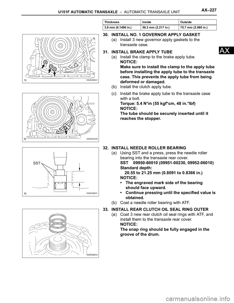
30. INSTALL NO. 1 GOVERNOR APPLY GASKET
(a) Install 3 new governor apply gaskets to the
transaxle case.
31. INSTALL BRAKE APPLY TUBE
(a) Install the clamp to the brake apply tube.
NOTICE:
Make sure to install the clamp to the apply tube
before installing the apply tube to the transaxle
case. This prevents the apply tube from being
deformed or damaged.
(b) Install the clutch apply tube.
(c) Install the brake apply tube to the transaxle case
with a bolt.
Torque: 5.4 N*m (55 kgf*cm, 48 in.*lbf)
NOTICE:
The tube should be securely inserted until it
reaches the stopper.
32. INSTALL NEEDLE ROLLER BEARING
(a) Using SST and a press, press the needle roller
bearing into the transaxle rear cover.
SST 09950-60010 (09951-00230, 09952-06010)
Standard depth:
20.55 to 21.25 mm (0.8091 to 0.8366 in.)
NOTICE:
• The engraved mark side of the bearing
should face upward.
• Continue pressing until the specified value is
obtained.
(b) Coat a needle roller bearing with ATF.
33. INSTALL REAR CLUTCH OIL SEAL RING OUTER
(a) Coat 3 new rear clutch oil seal rings with ATF, and
install them to the transaxle rear cover.
NOTICE:
The snap ring should be fully engaged in the
groove of the drum.
3.8 mm (0.1496 in.) 56.3 mm (2.217 in.) 75.7 mm (2.980 in.) Thickness Inside Outside
D026390E01
D026391E05
D026766E01
D026389E03
Page 1206 of 2000
AX–228U151F AUTOMATIC TRANSAXLE – AUTOMATIC TRANSAXLE UNIT
AX
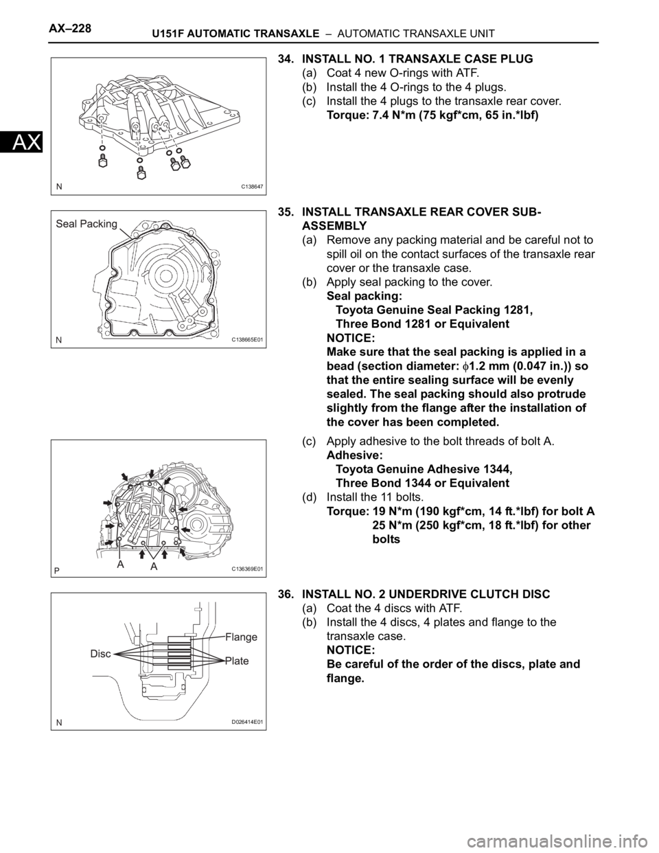
34. INSTALL NO. 1 TRANSAXLE CASE PLUG
(a) Coat 4 new O-rings with ATF.
(b) Install the 4 O-rings to the 4 plugs.
(c) Install the 4 plugs to the transaxle rear cover.
Torque: 7.4 N*m (75 kgf*cm, 65 in.*lbf)
35. INSTALL TRANSAXLE REAR COVER SUB-
ASSEMBLY
(a) Remove any packing material and be careful not to
spill oil on the contact surfaces of the transaxle rear
cover or the transaxle case.
(b) Apply seal packing to the cover.
Seal packing:
Toyota Genuine Seal Packing 1281,
Three Bond 1281 or Equivalent
NOTICE:
Make sure that the seal packing is applied in a
bead (section diameter:
1.2 mm (0.047 in.)) so
that the entire sealing surface will be evenly
sealed. The seal packing should also protrude
slightly from the flange after the installation of
the cover has been completed.
(c) Apply adhesive to the bolt threads of bolt A.
Adhesive:
Toyota Genuine Adhesive 1344,
Three Bond 1344 or Equivalent
(d) Install the 11 bolts.
Torque: 19 N*m (190 kgf*cm, 14 ft.*lbf) for bolt A
25 N*m (250 kgf*cm, 18 ft.*lbf) for other
bolts
36. INSTALL NO. 2 UNDERDRIVE CLUTCH DISC
(a) Coat the 4 discs with ATF.
(b) Install the 4 discs, 4 plates and flange to the
transaxle case.
NOTICE:
Be careful of the order of the discs, plate and
flange.
C138647
C138665E01
C136369E01
D026414E01
Page 1210 of 2000
AX–232U151F AUTOMATIC TRANSAXLE – AUTOMATIC TRANSAXLE UNIT
AX
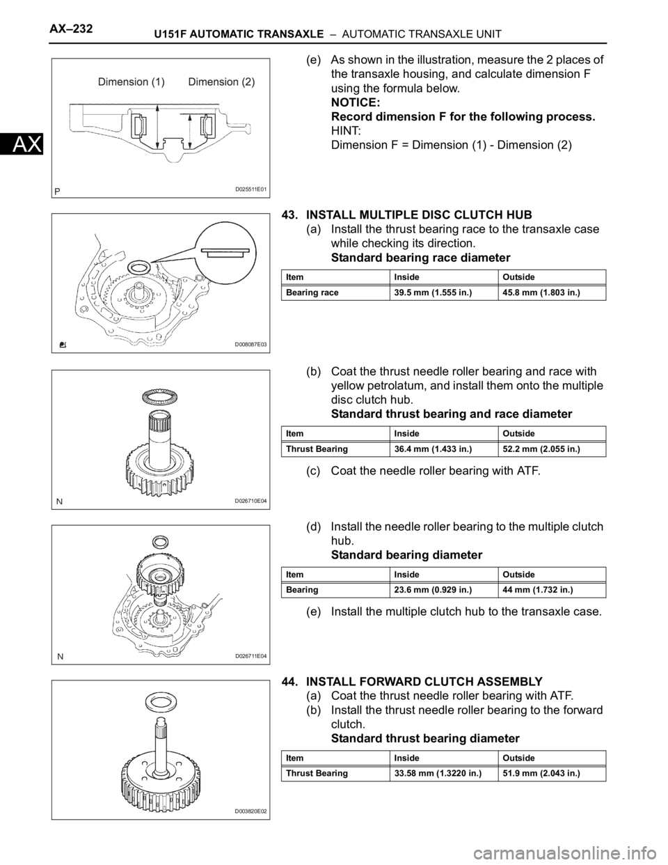
(e) As shown in the illustration, measure the 2 places of
the transaxle housing, and calculate dimension F
using the formula below.
NOTICE:
Record dimension F for the following process.
HINT:
Dimension F = Dimension (1) - Dimension (2)
43. INSTALL MULTIPLE DISC CLUTCH HUB
(a) Install the thrust bearing race to the transaxle case
while checking its direction.
Standard bearing race diameter
(b) Coat the thrust needle roller bearing and race with
yellow petrolatum, and install them onto the multiple
disc clutch hub.
Standard thrust bearing and race diameter
(c) Coat the needle roller bearing with ATF.
(d) Install the needle roller bearing to the multiple clutch
hub.
Standard bearing diameter
(e) Install the multiple clutch hub to the transaxle case.
44. INSTALL FORWARD CLUTCH ASSEMBLY
(a) Coat the thrust needle roller bearing with ATF.
(b) Install the thrust needle roller bearing to the forward
clutch.
Standard thrust bearing diameter
D025511E01
D008087E03
Item Inside Outside
Bearing race 39.5 mm (1.555 in.) 45.8 mm (1.803 in.)
D026710E04
Item Inside Outside
Thrust Bearing 36.4 mm (1.433 in.) 52.2 mm (2.055 in.)
D026711E04
Item Inside Outside
Bearing 23.6 mm (0.929 in.) 44 mm (1.732 in.)
D003820E02
Item Inside Outside
Thrust Bearing 33.58 mm (1.3220 in.) 51.9 mm (2.043 in.)
Page 1212 of 2000
AX–234U151F AUTOMATIC TRANSAXLE – AUTOMATIC TRANSAXLE UNIT
AX
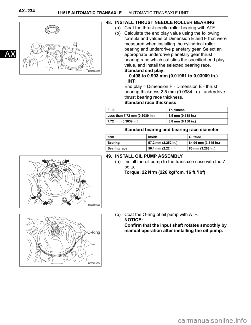
48. INSTALL THRUST NEEDLE ROLLER BEARING
(a) Coat the thrust needle roller bearing with ATF.
(b) Calculate the end play value using the following
formula and values of Dimension E and F that were
measured when installing the cylindrical roller
bearing and underdrive planetary gear. Select an
appropriate underdrive planetary gear thrust
bearing race which satisfies the specified end play
value, and install the selected bearing race.
Standard end play:
0.498 to 0.993 mm (0.01961 to 0.03909 in.)
HINT:
End play = Dimension F - Dimension E - thrust
bearing thickness 2.5 mm (0.0984 in.) - underdrive
thrust bearing race thickness.
Standard race thickness
Standard bearing and bearing race diameter
49. INSTALL OIL PUMP ASSEMBLY
(a) Install the oil pump to the transaxle case with the 7
bolts.
Torque: 22 N*m (226 kgf*cm, 16 ft.*lbf)
(b) Coat the O-ring of oil pump with ATF.
NOTICE:
Confirm that the input shaft rotates smoothly by
manual operation after installing the oil pump.
D025505E03
F - E Thickness
Less than 7.72 mm (0.3039 in.) 3.5 mm (0.138 in.)
7.72 mm (0.3039 in.) 3.8 mm (0.150 in.)
Item Inside Outside
Bearing 57.2 mm (2.252 in.) 84.96 mm (3.345 in.)
Bearing race 56.4 mm (2.22 in.) 83 mm (3.268 in.)
D003569E03
D003629E04
Page 1215 of 2000
U151F AUTOMATIC TRANSAXLE – AUTOMATIC TRANSAXLE UNITAX–237
AX
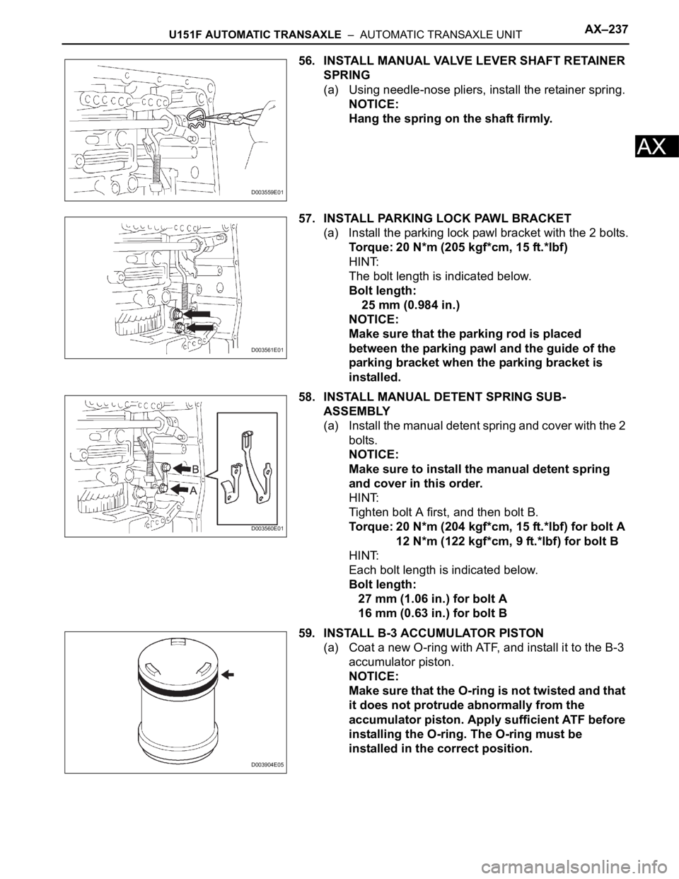
56. INSTALL MANUAL VALVE LEVER SHAFT RETAINER
SPRING
(a) Using needle-nose pliers, install the retainer spring.
NOTICE:
Hang the spring on the shaft firmly.
57. INSTALL PARKING LOCK PAWL BRACKET
(a) Install the parking lock pawl bracket with the 2 bolts.
Torque: 20 N*m (205 kgf*cm, 15 ft.*lbf)
HINT:
The bolt length is indicated below.
Bolt length:
25 mm (0.984 in.)
NOTICE:
Make sure that the parking rod is placed
between the parking pawl and the guide of the
parking bracket when the parking bracket is
installed.
58. INSTALL MANUAL DETENT SPRING SUB-
ASSEMBLY
(a) Install the manual detent spring and cover with the 2
bolts.
NOTICE:
Make sure to install the manual detent spring
and cover in this order.
HINT:
Tighten bolt A first, and then bolt B.
Torque: 20 N*m (204 kgf*cm, 15 ft.*lbf) for bolt A
12 N*m (122 kgf*cm, 9 ft.*lbf) for bolt B
HINT:
Each bolt length is indicated below.
Bolt length:
27 mm (1.06 in.) for bolt A
16 mm (0.63 in.) for bolt B
59. INSTALL B-3 ACCUMULATOR PISTON
(a) Coat a new O-ring with ATF, and install it to the B-3
accumulator piston.
NOTICE:
Make sure that the O-ring is not twisted and that
it does not protrude abnormally from the
accumulator piston. Apply sufficient ATF before
installing the O-ring. The O-ring must be
installed in the correct position.
D003559E01
D003561E01
D003560E01
D003904E05
Page 1216 of 2000
AX–238U151F AUTOMATIC TRANSAXLE – AUTOMATIC TRANSAXLE UNIT
AX
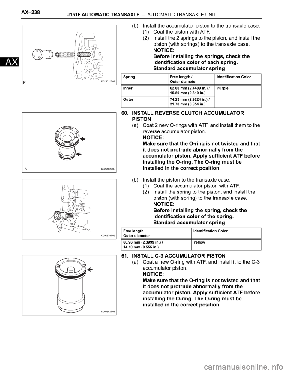
(b) Install the accumulator piston to the transaxle case.
(1) Coat the piston with ATF.
(2) Install the 2 springs to the piston, and install the
piston (with springs) to the transaxle case.
NOTICE:
Before installing the springs, check the
identification color of each spring.
Standard accumulator spring
60. INSTALL REVERSE CLUTCH ACCUMULATOR
PISTON
(a) Coat 2 new O-rings with ATF, and install them to the
reverse accumulator piston.
NOTICE:
Make sure that the O-ring is not twisted and that
it does not protrude abnormally from the
accumulator piston. Apply sufficient ATF before
installing the O-ring. The O-ring must be
installed in the correct position.
(b) Install the piston to the transaxle case.
(1) Coat the accumulator piston with ATF.
(2) Install the spring to the piston, and install the
piston (with spring) to the transaxle case.
NOTICE:
Before installing the spring, check the
identification color of the spring.
Standard accumulator spring
61. INSTALL C-3 ACCUMULATOR PISTON
(a) Coat a new O-ring with ATF, and install it to the C-3
accumulator piston.
NOTICE:
Make sure that the O-ring is not twisted and that
it does not protrude abnormally from the
accumulator piston. Apply sufficient ATF before
installing the O-ring. The O-ring must be
installed in the correct position.
D025512E02Spring Free length /
Outer diameterIdentification Color
Inner 62.00 mm (2.4409 in.) /
15.50 mm (0.610 in.)Purple
Outer 74.23 mm (2.9224 in.) /
21.70 mm (0.854 in.)
D026402E09
C092978E03Free length
Outer diameterIdentification Color
60.96 mm (2.3999 in.) /
14.10 mm (0.555 in.)Yellow
D003902E02
Page 1217 of 2000
U151F AUTOMATIC TRANSAXLE – AUTOMATIC TRANSAXLE UNITAX–239
AX
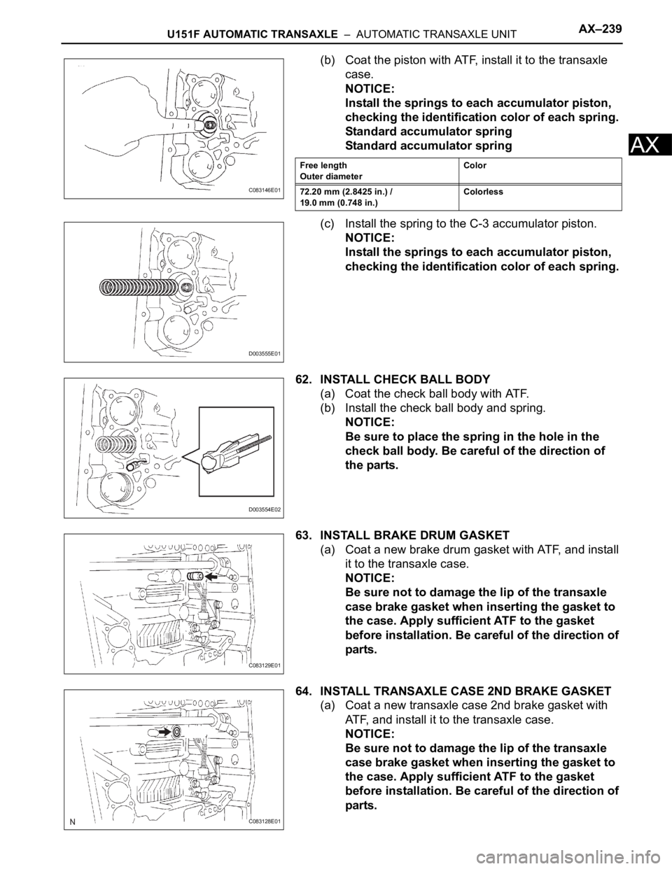
(b) Coat the piston with ATF, install it to the transaxle
case.
NOTICE:
Install the springs to each accumulator piston,
checking the identification color of each spring.
Standard accumulator spring
Standard accumulator spring
(c) Install the spring to the C-3 accumulator piston.
NOTICE:
Install the springs to each accumulator piston,
checking the identification color of each spring.
62. INSTALL CHECK BALL BODY
(a) Coat the check ball body with ATF.
(b) Install the check ball body and spring.
NOTICE:
Be sure to place the spring in the hole in the
check ball body. Be careful of the direction of
the parts.
63. INSTALL BRAKE DRUM GASKET
(a) Coat a new brake drum gasket with ATF, and install
it to the transaxle case.
NOTICE:
Be sure not to damage the lip of the transaxle
case brake gasket when inserting the gasket to
the case. Apply sufficient ATF to the gasket
before installation. Be careful of the direction of
parts.
64. INSTALL TRANSAXLE CASE 2ND BRAKE GASKET
(a) Coat a new transaxle case 2nd brake gasket with
ATF, and install it to the transaxle case.
NOTICE:
Be sure not to damage the lip of the transaxle
case brake gasket when inserting the gasket to
the case. Apply sufficient ATF to the gasket
before installation. Be careful of the direction of
parts.
C083146E01
Free length
Outer diameterColor
72.20 mm (2.8425 in.) /
19.0 mm (0.748 in.)Colorless
D003555E01
D003554E02
C083129E01
C083128E01
Page 1218 of 2000
AX–240U151F AUTOMATIC TRANSAXLE – AUTOMATIC TRANSAXLE UNIT
AX
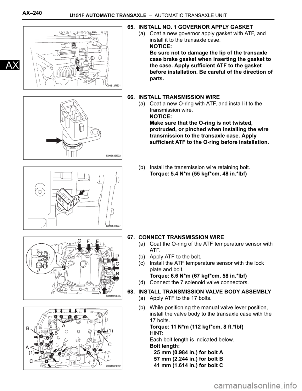
65. INSTALL NO. 1 GOVERNOR APPLY GASKET
(a) Coat a new governor apply gasket with ATF, and
install it to the transaxle case.
NOTICE:
Be sure not to damage the lip of the transaxle
case brake gasket when inserting the gasket to
the case. Apply sufficient ATF to the gasket
before installation. Be careful of the direction of
parts.
66. INSTALL TRANSMISSION WIRE
(a) Coat a new O-ring with ATF, and install it to the
transmission wire.
NOTICE:
Make sure that the O-ring is not twisted,
protruded, or pinched when installing the wire
transmission to the transaxle case. Apply
sufficient ATF to the O-ring before installation.
(b) Install the transmission wire retaining bolt.
Torque: 5.4 N*m (55 kgf*cm, 48 in.*lbf)
67. CONNECT TRANSMISSION WIRE
(a) Coat the O-ring of the ATF temperature sensor with
AT F.
(b) Apply ATF to the bolt.
(c) Install the ATF temperature sensor with the lock
plate and bolt.
Torque: 6.6 N*m (67 kgf*cm, 58 in.*lbf)
(d) Connect the 7 solenoid valve connectors.
68. INSTALL TRANSMISSION VALVE BODY ASSEMBLY
(a) Apply ATF to the 17 bolts.
(b) While positioning the manual valve lever position,
install the valve body to the transaxle case with the
17 bolts.
Torque: 11 N*m (112 kgf*cm, 8 ft.*lbf)
HINT:
Each bolt length is indicated below.
Bolt length:
25 mm (0.984 in.) for bolt A
57 mm (2.244 in.) for bolt B
41 mm (1.614 in.) for bolt C
C083127E01
D003636E02
D003547E07
C091927E05
C091933E02