Page 1163 of 2000
U151F AUTOMATIC TRANSAXLE – DIFFERENTIAL OIL SEALAX–171
AX
(f) Remove the transaxle housing oil seal RH.
(1) Using a screwdriver with vinyl tape wound
around its tip, remove the oil seal.
NOTICE:
Be careful not to damage the housing.
(g) Install a new transaxle housing oil seal RH.
(1) Coat the lip of a new oil seal with MP grease.
(2) Using SST and a hammer, tap in the oil seal.
SST 09649-17010, 09950-70010 (09951-
07200)
Standard depth:
6.0 +-0.5 mm (0.236 +-0.020 in.)
(h) Install the transfer assembly (see page TF-75).
(i) Install the rear engine mounting bracket with the 3
bolts.
Torque: 64 N*m (652 kgf*cm, 47 ft.*lbf)
(j) Install the drive shaft bearing bracket with the 3
bolts.
Torque: 64 N*m (653 kgf*cm, 47 ft.*lbf)
(k) Install the engine with transaxle (see page EM-31).
(l) Add automatic transaxle fluid.
Fluid type:
Toyota Genuine ATF WS
(m) Inspect the fluid level (see page AX-126).
D030693E01
D030913E02
Page 1164 of 2000
AX–176U151F AUTOMATIC TRANSAXLE – AUTOMATIC TRANSAXLE ASSEMBLY
AX
INSTALLATION
1. INSPECT TORQUE CONVERTER CLUTCH
ASSEMBLY
(a) Inspect the torque converter clutch (see page AX-
179).
2. INSTALL TORQUE CONVERTER CLUTCH
ASSEMBLY
(a) Install the torque converter clutch to the automatic
transaxle.
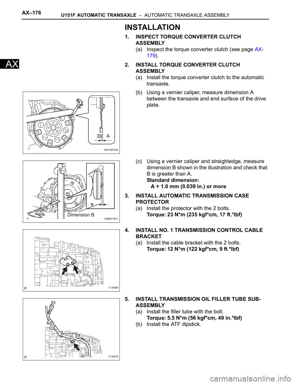
(b) Using a vernier caliper, measure dimension A
between the transaxle and end surface of the drive
plate.
(c) Using a vernier caliper and straightedge, measure
dimension B shown in the illustration and check that
B is greater than A.
Standard dimension:
A + 1.0 mm (0.039 in.) or more
3. INSTALL AUTOMATIC TRANSMISSION CASE
PROTECTOR
(a) Install the protector with the 2 bolts.
Torque: 23 N*m (235 kgf*cm, 17 ft.*lbf)
4. INSTALL NO. 1 TRANSMISSION CONTROL CABLE
BRACKET
(a) Install the cable bracket with the 2 bolts.
Torque: 12 N*m (122 kgf*cm, 9 ft.*lbf)
5. INSTALL TRANSMISSION OIL FILLER TUBE SUB-
ASSEMBLY
(a) Install the filler tube with the bolt.
Torque: 5.5 N*m (56 kgf*cm, 49 in.*lbf)
(b) Install the ATF dipstick.
D031087E02
C065911E01
C134980
C134979
Page 1166 of 2000
AX–178U151F AUTOMATIC TRANSAXLE – AUTOMATIC TRANSAXLE ASSEMBLY
AX
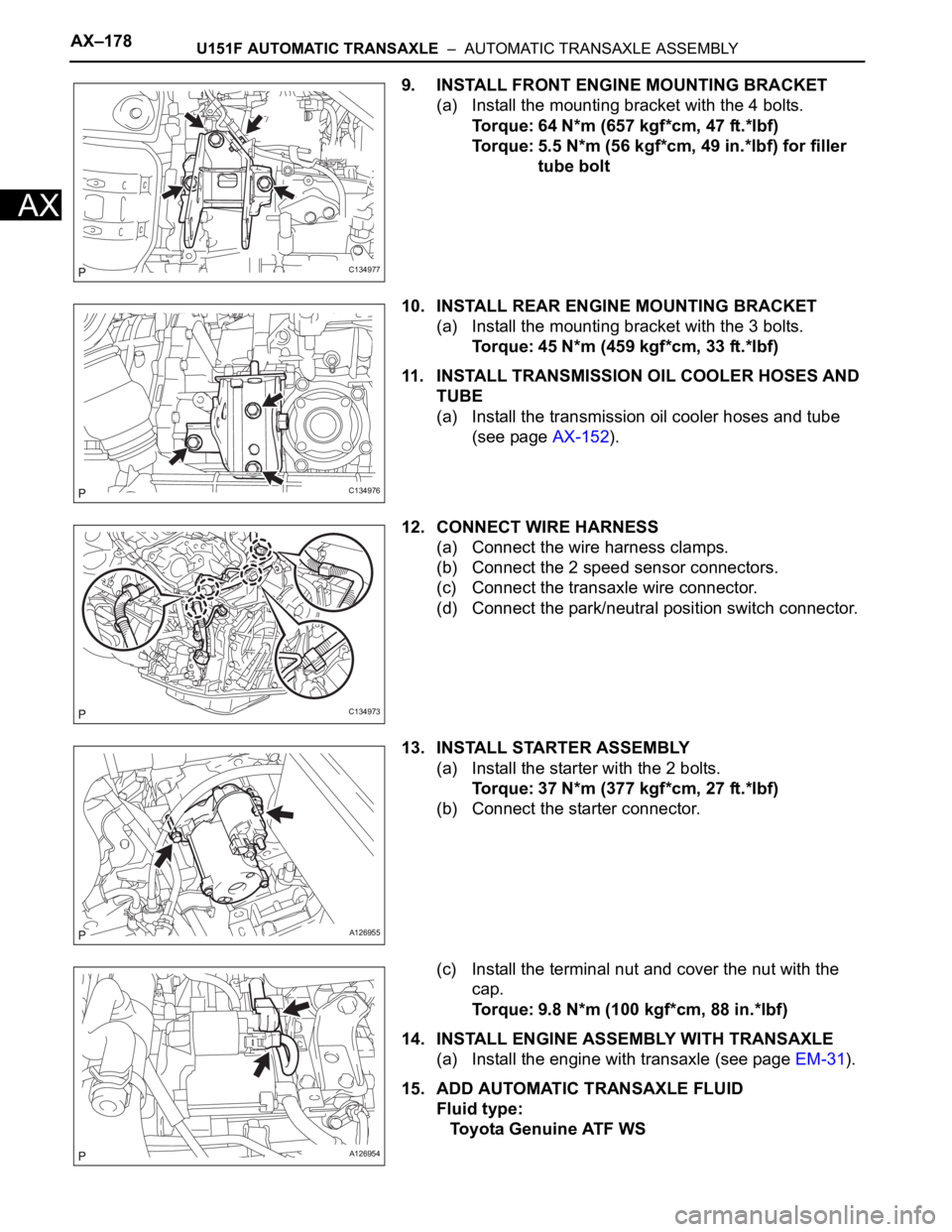
9. INSTALL FRONT ENGINE MOUNTING BRACKET
(a) Install the mounting bracket with the 4 bolts.
Torque: 64 N*m (657 kgf*cm, 47 ft.*lbf)
Torque: 5.5 N*m (56 kgf*cm, 49 in.*lbf) for filler
tube bolt
10. INSTALL REAR ENGINE MOUNTING BRACKET
(a) Install the mounting bracket with the 3 bolts.
Torque: 45 N*m (459 kgf*cm, 33 ft.*lbf)
11. INSTALL TRANSMISSION OIL COOLER HOSES AND
TUBE
(a) Install the transmission oil cooler hoses and tube
(see page AX-152).
12. CONNECT WIRE HARNESS
(a) Connect the wire harness clamps.
(b) Connect the 2 speed sensor connectors.
(c) Connect the transaxle wire connector.
(d) Connect the park/neutral position switch connector.
13. INSTALL STARTER ASSEMBLY
(a) Install the starter with the 2 bolts.
Torque: 37 N*m (377 kgf*cm, 27 ft.*lbf)
(b) Connect the starter connector.
(c) Install the terminal nut and cover the nut with the
cap.
Torque: 9.8 N*m (100 kgf*cm, 88 in.*lbf)
14. INSTALL ENGINE ASSEMBLY WITH TRANSAXLE
(a) Install the engine with transaxle (see page EM-31).
15. ADD AUTOMATIC TRANSAXLE FLUID
Fluid type:
Toyota Genuine ATF WS
C134977
C134976
C134973
A126955
A126954
Page 1172 of 2000
AX–194U151F AUTOMATIC TRANSAXLE – AUTOMATIC TRANSAXLE UNIT
AX
18. REMOVE C-3 ACCUMULATOR PISTON
(a) Remove the spring from the C-3 accumulator
piston.
(b) Apply compressed air (392 kPa, 4.0 kgf/cm
2, 57 psi)
to the oil hole and remove the C-3 accumulator
piston.
NOTICE:
• Applying compressed air may cause the
piston to jump out. When removing the
piston, hold it using a waste cloth.
• Take care not to splash ATF when applying
compressed air.
(c) Remove the O-ring from the C-3 accumulator
piston.
19. REMOVE REVERSE CLUTCH ACCUMULATOR
PISTON
(a) Apply compressed air (392 kPa, 4.0 kgf/cm
2, 57 psi)
to the oil hole and remove the reverse accumulator
piston and spring.
NOTICE:
• Applying compressed air may cause the
piston to jump out. When removing the
piston, hold it using a waste cloth.
• Take care not to splash ATF when applying
compressed air.
(b) Remove the 2 O-rings from the reverse clutch
accumulator piston.
D003555E01
D003556E01
D003902E02
D026401E01
D026402E09
Page 1173 of 2000
U151F AUTOMATIC TRANSAXLE – AUTOMATIC TRANSAXLE UNITAX–195
AX
20. REMOVE B-3 ACCUMULATOR PISTON
(a) Apply compressed air (392 kPa, 4.0 kgf/cm
2, 57 psi)
to the oil hole and remove the B-3 accumulator
piston and 2 springs.
NOTICE:
• Applying compressed air may cause the
piston to jump out. When removing the
piston, hold it using a waste cloth.
• Take care not to splash ATF when applying
compressed air.
(b) Remove the O-ring from the B-3 accumulator
piston.
21. REMOVE MANUAL VALVE LEVER SHAFT RETAINER
SPRING
(a) Using needle-nose pliers, remove the manual valve
lever shaft retainer spring.
22. REMOVE MANUAL DETENT SPRING SUB-
ASSEMBLY
(a) Remove the 2 bolts, manual detent spring and
cover.
23. REMOVE PARKING LOCK PAWL BRACKET
(a) Remove the 2 bolts and parking lock pawl bracket.
D003558E01
D003904E05
D003559E01
D003560E03
C056727E01
Page 1184 of 2000
AX–206U151F AUTOMATIC TRANSAXLE – AUTOMATIC TRANSAXLE UNIT
AX
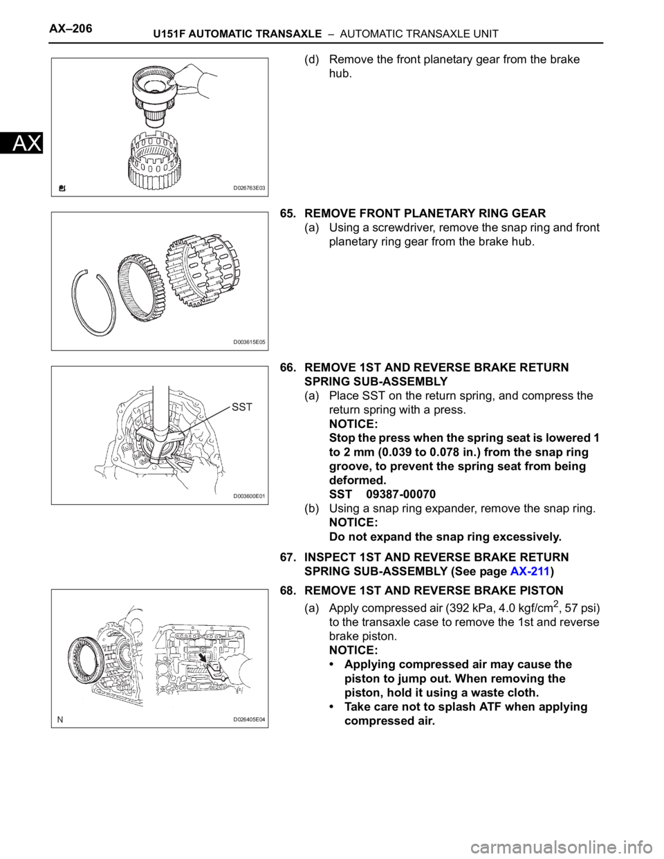
(d) Remove the front planetary gear from the brake
hub.
65. REMOVE FRONT PLANETARY RING GEAR
(a) Using a screwdriver, remove the snap ring and front
planetary ring gear from the brake hub.
66. REMOVE 1ST AND REVERSE BRAKE RETURN
SPRING SUB-ASSEMBLY
(a) Place SST on the return spring, and compress the
return spring with a press.
NOTICE:
Stop the press when the spring seat is lowered 1
to 2 mm (0.039 to 0.078 in.) from the snap ring
groove, to prevent the spring seat from being
deformed.
SST 09387-00070
(b) Using a snap ring expander, remove the snap ring.
NOTICE:
Do not expand the snap ring excessively.
67. INSPECT 1ST AND REVERSE BRAKE RETURN
SPRING SUB-ASSEMBLY (See page AX-211)
68. REMOVE 1ST AND REVERSE BRAKE PISTON
(a) Apply compressed air (392 kPa, 4.0 kgf/cm
2, 57 psi)
to the transaxle case to remove the 1st and reverse
brake piston.
NOTICE:
• Applying compressed air may cause the
piston to jump out. When removing the
piston, hold it using a waste cloth.
• Take care not to splash ATF when applying
compressed air.
D026763E03
D003615E05
D003600E01
D026405E04
Page 1188 of 2000
AX–210U151F AUTOMATIC TRANSAXLE – AUTOMATIC TRANSAXLE UNIT
AX
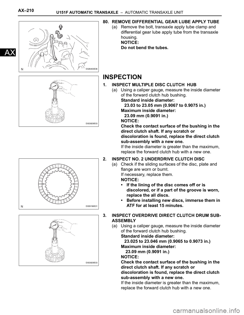
80. REMOVE DIFFERENTIAL GEAR LUBE APPLY TUBE
(a) Remove the bolt, transaxle apply tube clamp and
differential gear lube apply tube from the transaxle
housing.
NOTICE:
Do not bend the tubes.
INSPECTION
1. INSPECT MULTIPLE DISC CLUTCH HUB
(a) Using a caliper gauge, measure the inside diameter
of the forward clutch hub bushing.
Standard inside diameter:
23.03 to 23.05 mm (0.9067 to 0.9075 in.)
Maximum inside diameter:
23.09 mm (0.9091 in.)
NOTICE:
Check the contact surface of the bushing in the
direct clutch shaft. If any scratch or
discoloration is found, replace the direct clutch
sub-assembly with a new one.
If the inside diameter is greater than the maximum,
replace the forward clutch hub with a new one.
2. INSPECT NO. 2 UNDERDRIVE CLUTCH DISC
(a) Check if the sliding surfaces of the disc, plate and
flange are worn or burnt.
If necessary, replace them.
NOTICE:
• If the lining of the disc comes off or is
discolored, or if a part of the groove is worn,
replace the all discs.
• Before installing new discs, immerse them in
ATF for at least 15 minutes.
3. INSPECT OVERDRIVE DIRECT CLUTCH DRUM SUB-
ASSEMBLY
(a) Using a caliper gauge, measure the inside diameter
of the forward clutch hub bushing.
Standard inside diameter:
23.025 to 23.046 mm (0.9065 to 0.9073 in.)
Maximum inside diameter:
23.09 mm (0.9091 in.)
NOTICE:
Check the contact surface of the bushing in the
direct clutch shaft. If any scratch or
discoloration is found, replace the direct clutch
sub-assembly with a new one.
If the inside diameter is greater than the maximum,
replace the forward clutch hub with a new one.
D026400E06
D003829E03
D009196E01
D003829E03
Page 1189 of 2000
U151F AUTOMATIC TRANSAXLE – AUTOMATIC TRANSAXLE UNITAX–211
AX
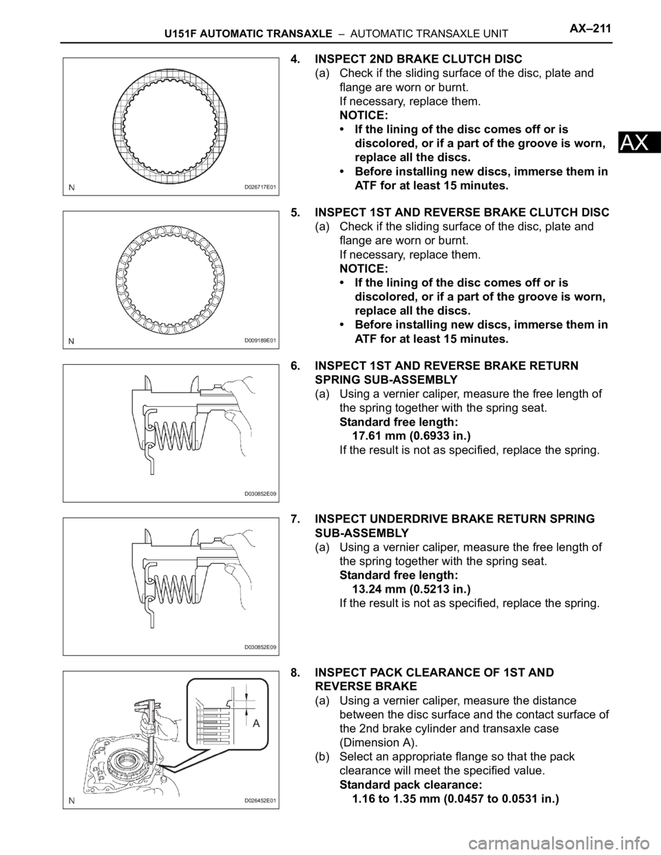
4. INSPECT 2ND BRAKE CLUTCH DISC
(a) Check if the sliding surface of the disc, plate and
flange are worn or burnt.
If necessary, replace them.
NOTICE:
• If the lining of the disc comes off or is
discolored, or if a part of the groove is worn,
replace all the discs.
• Before installing new discs, immerse them in
ATF for at least 15 minutes.
5. INSPECT 1ST AND REVERSE BRAKE CLUTCH DISC
(a) Check if the sliding surface of the disc, plate and
flange are worn or burnt.
If necessary, replace them.
NOTICE:
• If the lining of the disc comes off or is
discolored, or if a part of the groove is worn,
replace all the discs.
• Before installing new discs, immerse them in
ATF for at least 15 minutes.
6. INSPECT 1ST AND REVERSE BRAKE RETURN
SPRING SUB-ASSEMBLY
(a) Using a vernier caliper, measure the free length of
the spring together with the spring seat.
Standard free length:
17.61 mm (0.6933 in.)
If the result is not as specified, replace the spring.
7. INSPECT UNDERDRIVE BRAKE RETURN SPRING
SUB-ASSEMBLY
(a) Using a vernier caliper, measure the free length of
the spring together with the spring seat.
Standard free length:
13.24 mm (0.5213 in.)
If the result is not as specified, replace the spring.
8. INSPECT PACK CLEARANCE OF 1ST AND
REVERSE BRAKE
(a) Using a vernier caliper, measure the distance
between the disc surface and the contact surface of
the 2nd brake cylinder and transaxle case
(Dimension A).
(b) Select an appropriate flange so that the pack
clearance will meet the specified value.
Standard pack clearance:
1.16 to 1.35 mm (0.0457 to 0.0531 in.)
D026717E01
D009189E01
D030852E09
D030852E09
D026452E01