2006 TOYOTA RAV4 Ws atf
[x] Cancel search: Ws atfPage 1120 of 2000
AX–252U151E AUTOMATIC TRANSAXLE – SECOND BRAKE PISTON
AX
REASSEMBLY
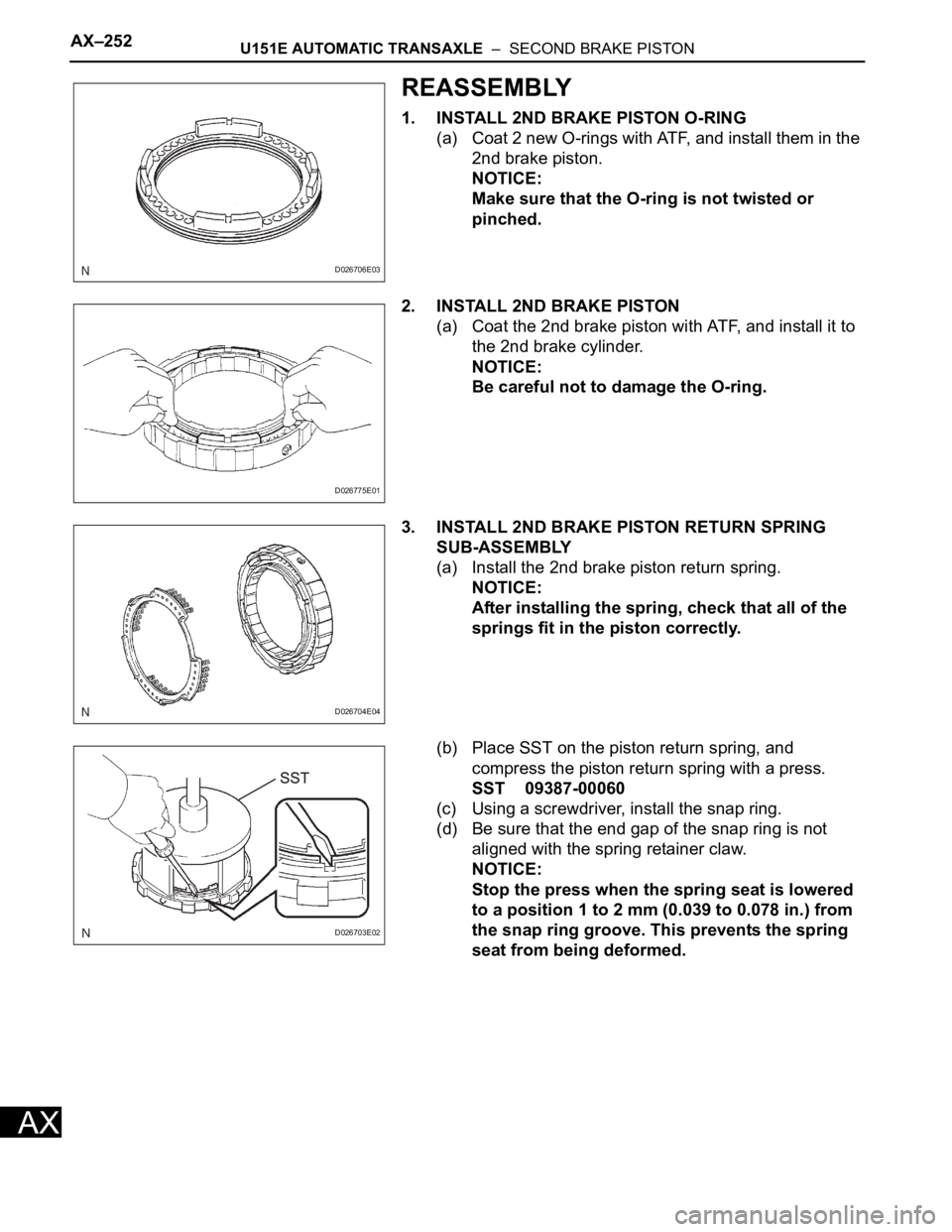
1. INSTALL 2ND BRAKE PISTON O-RING
(a) Coat 2 new O-rings with ATF, and install them in the
2nd brake piston.
NOTICE:
Make sure that the O-ring is not twisted or
pinched.
2. INSTALL 2ND BRAKE PISTON
(a) Coat the 2nd brake piston with ATF, and install it to
the 2nd brake cylinder.
NOTICE:
Be careful not to damage the O-ring.
3. INSTALL 2ND BRAKE PISTON RETURN SPRING
SUB-ASSEMBLY
(a) Install the 2nd brake piston return spring.
NOTICE:
After installing the spring, check that all of the
springs fit in the piston correctly.
(b) Place SST on the piston return spring, and
compress the piston return spring with a press.
SST 09387-00060
(c) Using a screwdriver, install the snap ring.
(d) Be sure that the end gap of the snap ring is not
aligned with the spring retainer claw.
NOTICE:
Stop the press when the spring seat is lowered
to a position 1 to 2 mm (0.039 to 0.078 in.) from
the snap ring groove. This prevents the spring
seat from being deformed.
D026706E03
D026775E01
D026704E04
D026703E02
Page 1122 of 2000
AX–256U151E AUTOMATIC TRANSAXLE – FORWARD CLUTCH
AX
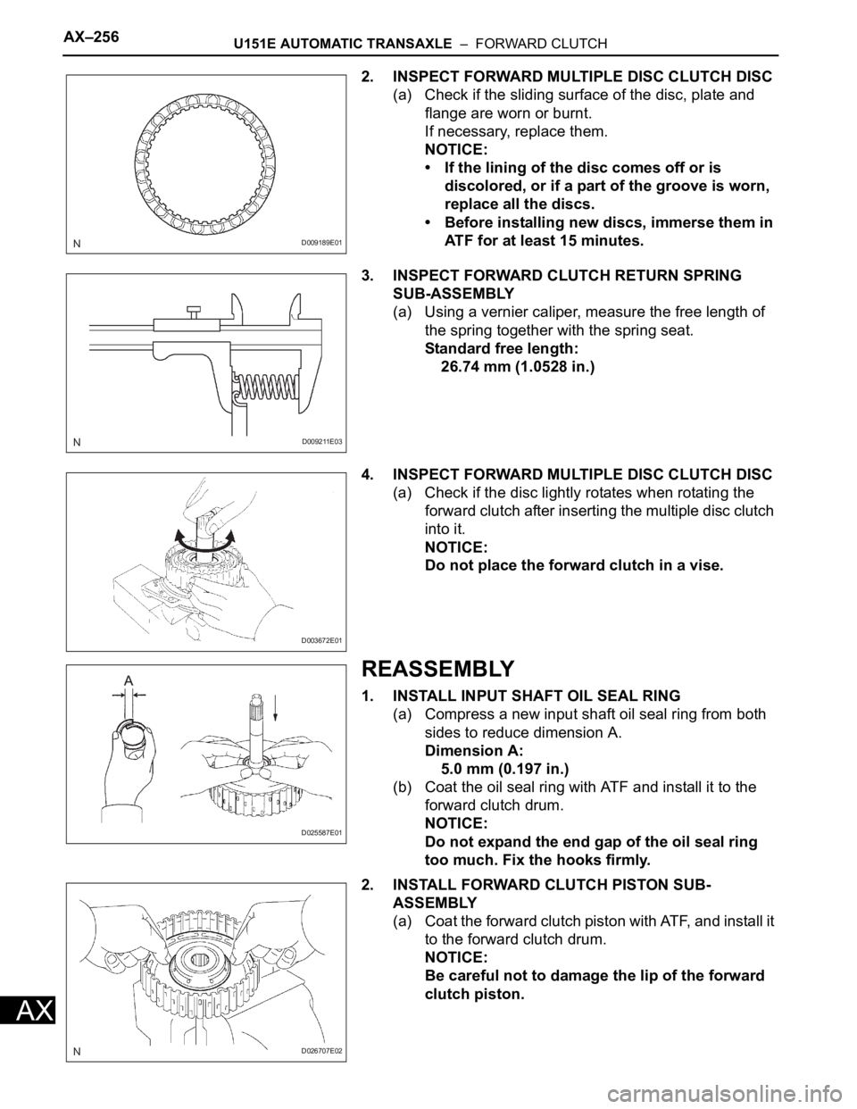
2. INSPECT FORWARD MULTIPLE DISC CLUTCH DISC
(a) Check if the sliding surface of the disc, plate and
flange are worn or burnt.
If necessary, replace them.
NOTICE:
• If the lining of the disc comes off or is
discolored, or if a part of the groove is worn,
replace all the discs.
• Before installing new discs, immerse them in
ATF for at least 15 minutes.
3. INSPECT FORWARD CLUTCH RETURN SPRING
SUB-ASSEMBLY
(a) Using a vernier caliper, measure the free length of
the spring together with the spring seat.
Standard free length:
26.74 mm (1.0528 in.)
4. INSPECT FORWARD MULTIPLE DISC CLUTCH DISC
(a) Check if the disc lightly rotates when rotating the
forward clutch after inserting the multiple disc clutch
into it.
NOTICE:
Do not place the forward clutch in a vise.
REASSEMBLY
1. INSTALL INPUT SHAFT OIL SEAL RING
(a) Compress a new input shaft oil seal ring from both
sides to reduce dimension A.
Dimension A:
5.0 mm (0.197 in.)
(b) Coat the oil seal ring with ATF and install it to the
forward clutch drum.
NOTICE:
Do not expand the end gap of the oil seal ring
too much. Fix the hooks firmly.
2. INSTALL FORWARD CLUTCH PISTON SUB-
ASSEMBLY
(a) Coat the forward clutch piston with ATF, and install it
to the forward clutch drum.
NOTICE:
Be careful not to damage the lip of the forward
clutch piston.
D009189E01
D009211E03
D003672E01
D025587E01
D026707E02
Page 1123 of 2000
U151E AUTOMATIC TRANSAXLE – FORWARD CLUTCHAX–257
AX
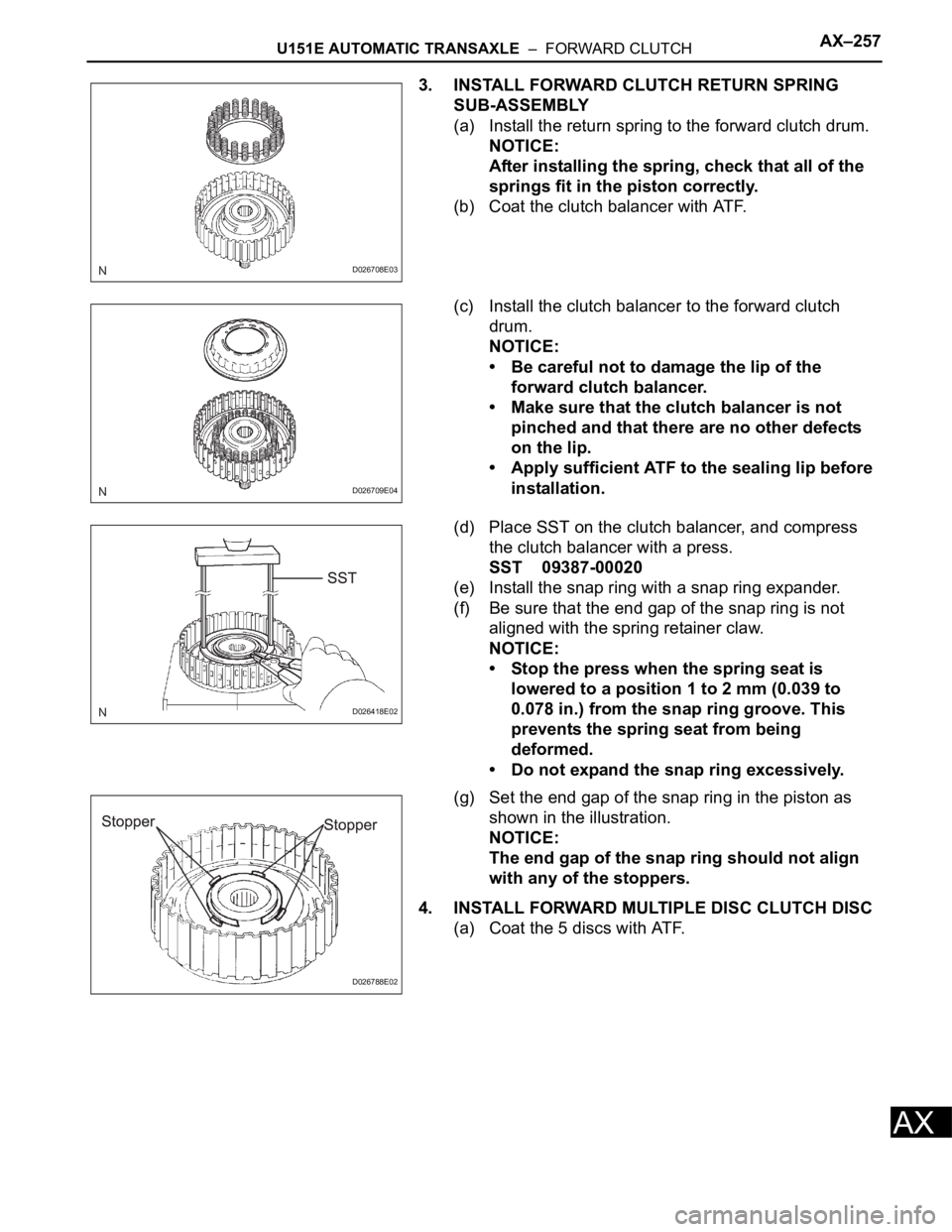
3. INSTALL FORWARD CLUTCH RETURN SPRING
SUB-ASSEMBLY
(a) Install the return spring to the forward clutch drum.
NOTICE:
After installing the spring, check that all of the
springs fit in the piston correctly.
(b) Coat the clutch balancer with ATF.
(c) Install the clutch balancer to the forward clutch
drum.
NOTICE:
• Be careful not to damage the lip of the
forward clutch balancer.
• Make sure that the clutch balancer is not
pinched and that there are no other defects
on the lip.
• Apply sufficient ATF to the sealing lip before
installation.
(d) Place SST on the clutch balancer, and compress
the clutch balancer with a press.
SST 09387-00020
(e) Install the snap ring with a snap ring expander.
(f) Be sure that the end gap of the snap ring is not
aligned with the spring retainer claw.
NOTICE:
• Stop the press when the spring seat is
lowered to a position 1 to 2 mm (0.039 to
0.078 in.) from the snap ring groove. This
prevents the spring seat from being
deformed.
• Do not expand the snap ring excessively.
(g) Set the end gap of the snap ring in the piston as
shown in the illustration.
NOTICE:
The end gap of the snap ring should not align
with any of the stoppers.
4. INSTALL FORWARD MULTIPLE DISC CLUTCH DISC
(a) Coat the 5 discs with ATF.
D026708E03
D026709E04
D026418E02
D026788E02
Page 1134 of 2000

U151F AUTOMATIC TRANSAXLE – AUTOMATIC TRANSAXLE SYSTEMAX–15
AX
ROAD TEST
1. PROBLEM SYMPTOM CONFIRMATION
(a) Based on the result of the customer problem
analysis, try to reproduce the symptoms. If the
problem is that the transaxle does not shift up, shift
down, or the shift point is too high or too low,
conduct the following road test referring to the
automatic shift schedule and simulate the problem
symptoms.
2. ROAD TEST
NOTICE:
Perform the test at the normal operating ATF
temperature of 50 to 80
C (122 to 176F).
(a) D position test:
Move the shift lever to D and fully depress the
accelerator pedal. Check the following:
(1) Check up-shift operation.
Check that the 1
2, 2 3, 3 4 and 4 5th
up-shifts take place at the shift point shown in
the automatic shift schedule (see page SS-49).
HINT:
5th Gear Up-shift Prohibition Control
• Engine coolant temperature is 55
C (131F)
or less and vehicle speed is at 80 km/h (50
mph) or less.
• ATF temperature is -2
C (28F) or less.
4th Gear Up-shift Prohibition Control
• Engine coolant temperature is 47
C (117F)
or less and vehicle speed is at 55 km/h (34
mph) or less.
5th and 4th Gear Lock-up Prohibition Control
• Brake pedal is depressed.
• Accelerator pedal is released.
• Engine coolant temperature is 60
C (140F)
or less.
(2) Check for shift shock and slip.
Check for shock and slip at the 1
2, 2 3, 3
4 and 4 5th up-shifts.
(3) Check for abnormal noise and vibration.
Check for abnormal noise and vibration when
up-shifting from 1
2, 2 3, 3 4 and 4
5th while driving with the shift lever on D, and
check while driving in the lock-up condition.
HINT:
The check for the cause of abnormal noise and
vibration must be done thoroughly as it could
also be due to loss of balance in the differential,
torque converter clutch, etc.
Page 1137 of 2000

AX–18U151F AUTOMATIC TRANSAXLE – AUTOMATIC TRANSAXLE SYSTEM
AX
MECHANICAL SYSTEM TESTS
1. STALL SPEED TEST
HINT:
This test is to check the overall performance of the
engine and transaxle.
NOTICE:
• Do not perform the stall speed test longer than 10
seconds.
• To ensure safety, perform this test in an open and
level area that provides good traction.
• The stall speed test should always be performed
with at least 2 people. One person should observe
the condition of the wheels and wheel chocks
while the other is performing the test.
(a) Connect the intelligent tester to the CAN VIM. Then
connect the CAN VIM to the DLC3.
(b) Run the vehicle until the transmission fluid
temperature has reached 50 to 80
C (122 to 176F).
(c) Allow the engine to idle with the air conditioning
OFF.
(d) Chock all 4 wheels.
(e) Set the parking brake and keep the brake pedal
depressed firmly with your left foot.
(f) Move the shift lever to the D position.
(g) Depress the accelerator pedal as much as possible
with your right foot.
(h) Read the engine rpm (stall speed) and release the
accelerator pedal immediately.
Standard value:
2,450 to 2,750 rpm
Evaluation:
NOTICE:
Perform the test at the normal operating ATF
temperature of 50 to 80
C (122 to 176F).
2. SHIFT TIME LAG TEST
HINT:
This test is to check the condition of the direct clutch,
forward clutch, 1st brake and reverse brake.
(a) Connect the intelligent tester to the CAN VIM. Then
connect the CAN VIM to the DLC3.
(b) Run the vehicle until the transmission fluid
temperature has reached 50 to 80
C (122 to 176F).
Test Result Possible Cause
Stall speed is lower than standard value • Engine power output may be insufficient
• Stator one-way clutch not operating properly
HINT:
If the value is less than the specified value by 600 rpm or more, the
torque converter could be faulty.
Stall speed is higher than standard value • Line pressure is too low
• Forward clutch slipping
• U/D (underdrive) brake slipping
• U/D (underdrive) one-way clutch is not operating properly
• No. 1 one-way clutch not operating properly
• Improper fluid level
Page 1139 of 2000
AX–20U151F AUTOMATIC TRANSAXLE – AUTOMATIC TRANSAXLE SYSTEM
AX
HYDRAULIC TEST
1. PERFORM HYDRAULIC TEST
(a) Measure the line pressure.
NOTICE:
• Perform the test at the normal operating ATF
temperature: 50 to 80
C (122 to 176F).
• The line pressure test should always be
performed with at least 2 people. One person
should observe the condition of the wheels or
wheel chocks while the other is performing
the test.
• Be careful to prevent SST's hose from
interfering with the exhaust pipe.
• This test must be performed after checking
and adjusting the engine.
• Perform the test with the A/C OFF.
• When conducting the stall test, do not
continue for more than 10 seconds.
(1) Warm up the ATF (Automatic Transmission
Fluid).
(2) Lift the vehicle up.
(3) Remove the engine under cover.
(4) Connect the intelligent tester to the DLC3.
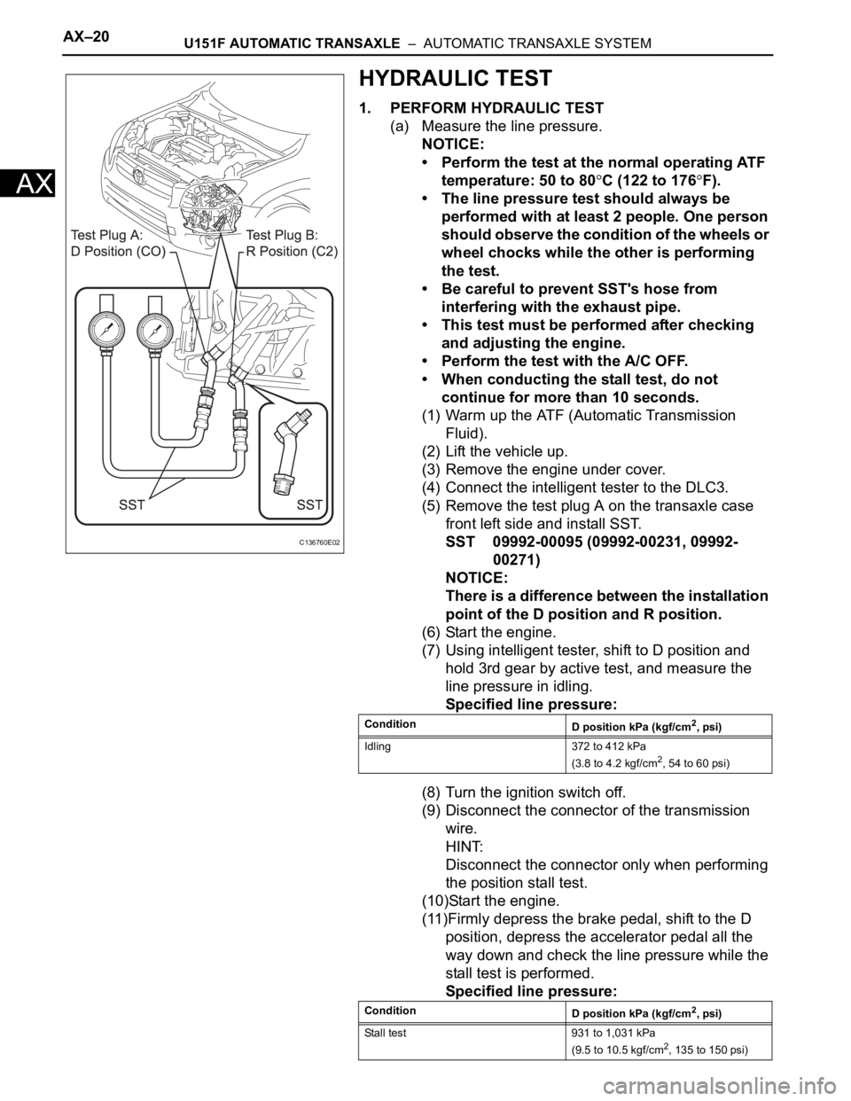
(5) Remove the test plug A on the transaxle case
front left side and install SST.
SST 09992-00095 (09992-00231, 09992-
00271)
NOTICE:
There is a difference between the installation
point of the D position and R position.
(6) Start the engine.
(7) Using intelligent tester, shift to D position and
hold 3rd gear by active test, and measure the
line pressure in idling.
Specified line pressure:
(8) Turn the ignition switch off.
(9) Disconnect the connector of the transmission
wire.
HINT:
Disconnect the connector only when performing
the position stall test.
(10)Start the engine.
(11)Firmly depress the brake pedal, shift to the D
position, depress the accelerator pedal all the
way down and check the line pressure while the
stall test is performed.
Specified line pressure:
C136760E02
Condition
D position kPa (kgf/cm2, psi)
Idling 372 to 412 kPa
(3.8 to 4.2 kgf/cm
2, 54 to 60 psi)
Condition
D position kPa (kgf/cm
2, psi)
Stall test 931 to 1,031 kPa
(9.5 to 10.5 kgf/cm
2, 135 to 150 psi)
Page 1150 of 2000

U151F AUTOMATIC TRANSAXLE – AUTOMATIC TRANSAXLE SYSTEMAX–31
AX
3 (B30-29) - E1 (B30-81) LG - BR 3 shift position switch
signalIgnition switch ON and
transfer shift lever on 310 to 14 V
3 (B30-29) - E1 (B30-81) LG - BR 3 shift position switch
signalIgnition switch ON and
transfer shift lever not on 3Below 1 V
2 (B30-28) - E1 (B30-81) V - BR 2 shift position switch
signalIgnition switch ON and
transfer shift lever on 2
and L10 to 14 V
2 (B30-28) - E1 (B30-81) V - BR 2 shift position switch
signalIgnition switch ON and
transfer shift lever not on 2
and LBelow 1 V
L (A9-26) - E1 (B30-81) V - BR L shift position switch
signalIgnition switch ON and
transfer shift lever on L10 to 14 V
L (A9-26) - E1 (B30-81) V - BR L shift position switch
signalIgnition switch ON and
transfer shift lever not on LBelow 1 V
STP (A9-36) - E1 (B30-81) L - BR Stop light switch signal Brake pedal is depressed Between 10 V and 14 V
STP (A9-36) - E1 (B30-81) L - BR Stop light switch signal Brake pedal is released Below 1 V
SL1+ (B30-16) - SL1-
(B30-17)P - LG SL1 solenoid signal Engine idle speed Pulse generation
(see waveform 1)
SL1+ (B30-16) - SL1-
(B30-17)P - LG SL1 solenoid signal Ignition switch ON Pulse generation
(see waveform 1)
SL1+ (B30-16) - SL1-
(B30-17)P - LG SL1 solenoid signal 1st gear Pulse generation
(see waveform 1)
SL1+ (B30-16) - SL1-
(B30-17)P - LG SL1 solenoid signal Not on 1st gear Below 1 V
SL2+ (B30-12) - SL2-
(B30-13)BR - R SL2 solenoid signal Engine idle speed Pulse generation
(see waveform 2)
SL2+ (B30-12) - SL2-
(B30-13)BR - R SL2 solenoid signal Ignition switch ON Pulse generation
(see waveform 2)
SL2+ (B30-12) - SL2-
(B30-13)BR - R SL2 solenoid signal 1st or 2nd gear Pulse generation
(see waveform 2)
SL2+ (B30-12) - SL2-
(B30-13)BR - R SL2 solenoid signal 3rd, 4th or 5th gear Below 1 V
SL3+ (B30-14) - SL3-
(B30-15)GR - G-R SL3 solenoid signal Engine idle speed Pulse generation
(see waveform 3)
SL3+ (B30-14) - SL3-
(B30-15)GR - G-R SL3 solenoid signal Ignition switch ON Pulse generation
(see waveform 3)
SL3+ (B30-14) - SL3-
(B30-15)GR - G-R SL3 solenoid signal 1st or 2nd gear Pulse generation
(see waveform 3)
SL3+ (B30-14) - SL3-
(B30-15)GR - G-R SL3 solenoid signal 3rd, 4th or 5th gear Below 1 V
DSL (B30-9) - E01 (B30-
22)V - BR DSL solenoid signal Vehicle speed 65 km/h (40
mph), lock-up (ON to OFF)Below 1 V
DSL (B30-9) - E01 (B30-
22)V - BR DSL solenoid signal Vehicle driving under lock-
up positionPulse generation
(see waveform 4)
SLT+ (B30-11) - SLT-
(B30-10)L - W SLT solenoid signal Engine idle speed Pulse generation
(see waveform 5)
SR (B30-8) - E01 (B30-22) G - BR SR solenoid signal Ignition switch ON Below 1 V
SR (B30-8) - E01 (B30-22) G - BR SR solenoid signal 3th, 4th or 5th gear 10 to 14 V
SR (B30-8) - E01 (B30-22) G - BR SR solenoid signal 1st or 2nd gear Below 1 V
S4 (B30-7) - E01 (B30-22) L-B - BR S4 solenoid signal Ignition switch ON Below 1 V
S4 (B30-7) - E01 (B30-22) L-B - BR S4 solenoid signal 5th gear 10 to 14 V
S4 (B30-7) - E01 (B30-22) L-B - BR S4 solenoid signal Not on 5th gear Below 1 V
THO1 (B30-126) - ETHO
(B30-124)Y - B ATF temperature sensor
signalATF temperature 115
C
(239
F) or moreBelow 1.5 V
NT+ (B30-6) - NT- (B30-5) B - G Speed sensor (NT) signal Vehicle speed 20 km/h (12
mph)Pulse generation
(see waveform 6) Symbols (Terminal No.) Wiring Color Terminal Description ConditionSpecified Condition
Page 1162 of 2000
AX–170U151F AUTOMATIC TRANSAXLE – DIFFERENTIAL OIL SEAL
AX
REPLACEMENT
1. REPLACE TRANSAXLE HOUSING OIL SEAL LH
(a) Drain the automatic transaxle fluid.
(1) Remove the drain plug and gasket, and drain
the ATF.
(2) Install a new gasket and drain plug.
Torque: 47 N*m (479 kgf*cm, 35 ft.*lbf)
(b) Remove the front drive shaft LH (see page DS-41).
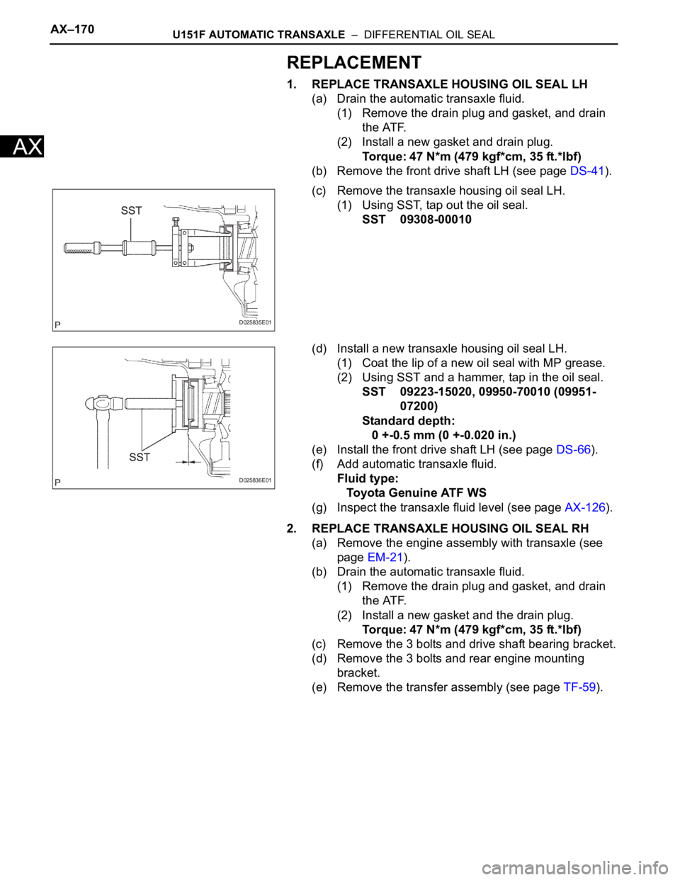
(c) Remove the transaxle housing oil seal LH.
(1) Using SST, tap out the oil seal.
SST 09308-00010
(d) Install a new transaxle housing oil seal LH.
(1) Coat the lip of a new oil seal with MP grease.
(2) Using SST and a hammer, tap in the oil seal.
SST 09223-15020, 09950-70010 (09951-
07200)
Standard depth:
0 +-0.5 mm (0 +-0.020 in.)
(e) Install the front drive shaft LH (see page DS-66).
(f) Add automatic transaxle fluid.
Fluid type:
Toyota Genuine ATF WS
(g) Inspect the transaxle fluid level (see page AX-126).
2. REPLACE TRANSAXLE HOUSING OIL SEAL RH
(a) Remove the engine assembly with transaxle (see
page EM-21).
(b) Drain the automatic transaxle fluid.
(1) Remove the drain plug and gasket, and drain
the ATF.
(2) Install a new gasket and the drain plug.
Torque: 47 N*m (479 kgf*cm, 35 ft.*lbf)
(c) Remove the 3 bolts and drive shaft bearing bracket.
(d) Remove the 3 bolts and rear engine mounting
bracket.
(e) Remove the transfer assembly (see page TF-59).
D025835E01
D025836E01