2006 NISSAN PATROL light
[x] Cancel search: lightPage 928 of 1226
COMPONENT INSPECTION
In-vehicle sensor
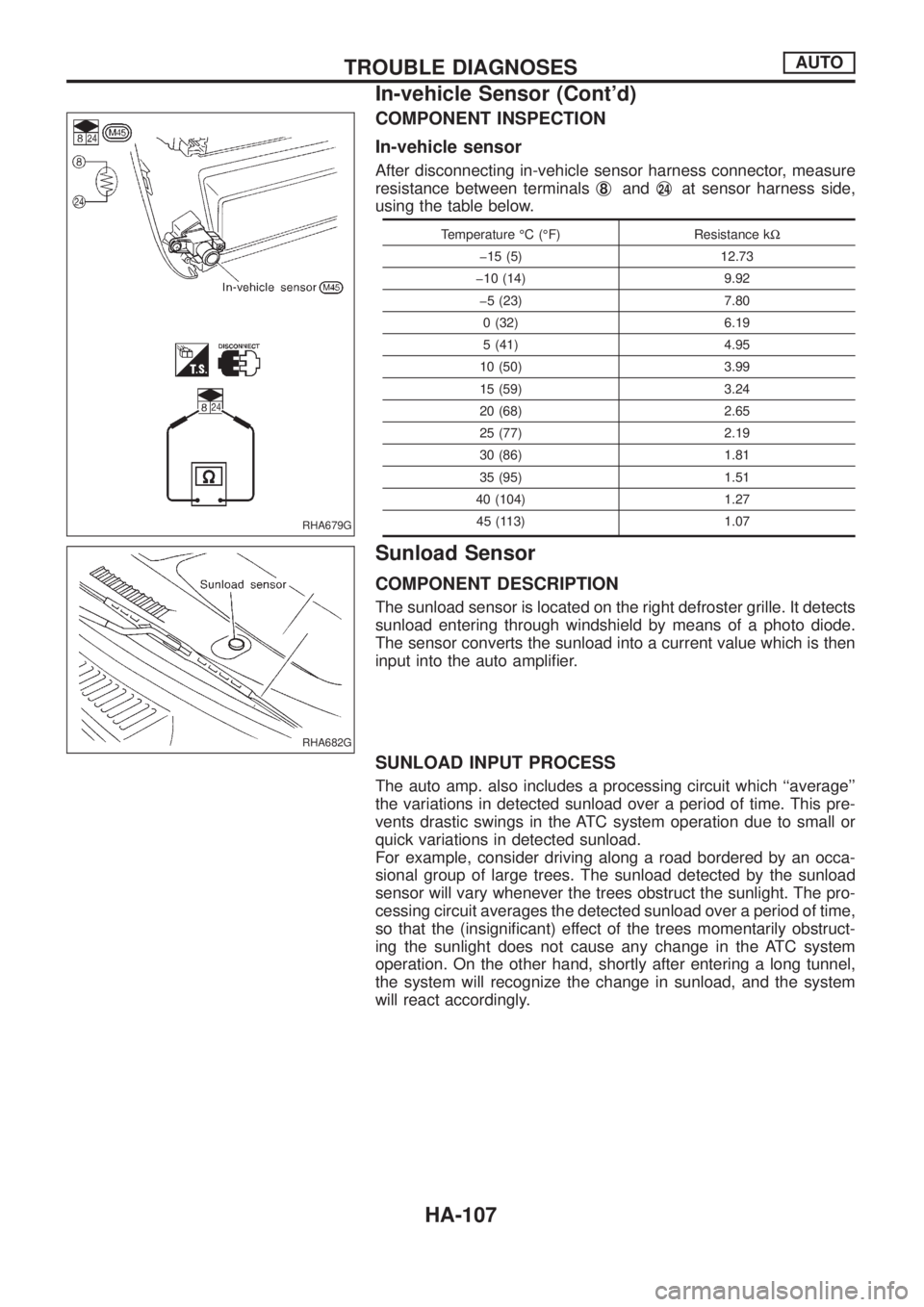
After disconnecting in-vehicle sensor harness connector, measure
resistance between terminalsj
8andj24at sensor harness side,
using the table below.
Temperature ÉC (ÉF) Resistance kW
þ15 (5) 12.73
þ10 (14) 9.92
þ5 (23) 7.80
0 (32) 6.19
5 (41) 4.95
10 (50) 3.99
15 (59) 3.24
20 (68) 2.65
25 (77) 2.19
30 (86) 1.81
35 (95) 1.51
40 (104) 1.27
45 (113) 1.07
Sunload Sensor
COMPONENT DESCRIPTION
The sunload sensor is located on the right defroster grille. It detects
sunload entering through windshield by means of a photo diode.
The sensor converts the sunload into a current value which is then
input into the auto ampli®er.
SUNLOAD INPUT PROCESS
The auto amp. also includes a processing circuit which ``average''
the variations in detected sunload over a period of time. This pre-
vents drastic swings in the ATC system operation due to small or
quick variations in detected sunload.
For example, consider driving along a road bordered by an occa-
sional group of large trees. The sunload detected by the sunload
sensor will vary whenever the trees obstruct the sunlight. The pro-
cessing circuit averages the detected sunload over a period of time,
so that the (insigni®cant) effect of the trees momentarily obstruct-
ing the sunlight does not cause any change in the ATC system
operation. On the other hand, shortly after entering a long tunnel,
the system will recognize the change in sunload, and the system
will react accordingly.
RHA679G
RHA682G
TROUBLE DIAGNOSESAUTO
In-vehicle Sensor (Cont'd)
HA-107
Page 949 of 1226
A
A/C HFC134a (R134a) system service
procedure ..................................................HA-112
A/C HFC134a system service equip-
ment precaution ............................................HA-9
A/C air ¯ow .....................................................HA-13
A/C component layout ....................................HA-12
A/C compressor precaution..............................HA-6
A/C compressor special service tool ...........HA-6, 7
A/C control linkage adjustment (auto
A/C).............................................................HA-77
A/C control operation (manual A/C) ...............HA-16
A/C harness layout (manual A/C) ..................HA-17
A/C lubricant (R134a) ...................................HA-114
A/C relay.........................................................HA-97
A/C self-diagnoses (auto A/C)........................HA-63
A/CCUT - Wiring diagram ............................EC-186
A/T control ....................................................EC-174
ABS sensor rotor ............................................FA-15
ACC/SW - Wiring diagram ...........................EC-105
ACL/SW - Wiring diagram ............................EC-164
ADJRES - Wiring diagram .............................EC-91
APS - Wiring diagram ..................................EC-138
AT/C - Wiring diagram..................................EC-174
AUDIO - Wiring diagram ...............................EL-168
Accelerator position sensor ..........................EC-138
Accelerator position switch...........................EC-164
Accelerator switch (F/C) ...............................EC-105
Adjustment resistor.........................................EC-91
Air bag disposal..............................................RS-17
Air bag ..............................................................RS-8
Air bleeding (hydraulic clutch) ..........................CL-6
Air bleeding for brake system ..........................BR-4
Air cleaner ®lter replacement .........................MA-18
Air conditioner cut control ..............................EC-19
Air ¯ow meter - See Mass air ¯ow
sensor .........................................................EC-73
Air mix door control linkage
adjustment ................................................HA-81
Alternator.........................................................EL-56
Antenna - See Power antenna .....................EL-181
Audio and A/C control removal and
installation - See Instrument panel .............BT-11
Audio .............................................................EL-168
Auto lock free running hub .............................FA-13
Automatic ampli®er .........................................HA-61
Axle housing (rear) ...........................................RA-9
B
BACK/L - Wiring diagram................................EL-78
Back door opener - See Back door ..................BT-6
Back door trim.................................................BT-24
Back door window...........................................BT-45
Back door ..........................................................BT-6Back-up lamp switch (M/T) ..............................MT-4
Back-up lamp ..................................................EL-78
Battery .............................................................EL-37
Baulk ring (M/T)..............................................MT-10
Body alignment ...............................................BT-49
Body mounting ................................................BT-48
Brake booster .................................................BR-15
Brake ¯uid change ...........................................BR-3
Brake ¯uid level and line check .......................BR-3
Brake ¯uid level .............................................MA-23
Brake hydraulic line ..........................................BR-5
Brake inspection ............................................MA-24
Brake master cylinder ....................................BR-12
Brake pedal ....................................................BR-10
Bulb speci®cations ........................................EL-314
Bumper, front ................................................... BT-4
Bumper, rear .....................................................BT-6
C
CD/CHG - Wiring diagram ............................EL-176
CHIME - Wiring diagram...............................EL-136
CIGAR - Wiring diagram ...............................EL-156
CKPS - Wiring diagram ................................EC-143
CLOCK - Wiring diagram ..............................EL-157
CMPS - Wiring diagram .................................EC-68
COMPAS - Wiring diagram ...........................EL-117
CONSULT for ECCS ......................................EC-36
CONSULT general information ........................GI-33
COOL/F - Wiring diagram ............................EC-112
CSPS - Wiring diagram ..................................EC-86
Cab body.........................................................BT-47
Camshaft inspection ......................................EM-36
Camshaft position sensor (PUMP).................EC-68
Center case (Transfer) ....................................TF-10
Charge air cooler fan control .......................EC-177
Charge air temperature sensor ....................EC-121
Chassis and body maintenance ....................MA-20
Cigarette lighter.............................................EL-156
Circuit breaker.................................................EL-14
Clock .............................................................EL-157
Clutch booster...................................................CL-9
Clutch cover ....................................................CL-14
Clutch damper ..................................................CL-7
Clutch disc ......................................................CL-13
Clutch ¯uid level.............................................MA-20
Clutch master cylinder ......................................CL-7
Clutch operating cylinder ..................................CL-8
Clutch pedal ......................................................CL-5
Clutch release bearing ....................................CL-11
Clutch release mechanism .............................CL-11
Clutch withdrawal lever ...................................CL-11
Coil spring (front) ............................................FA-25
Coil spring (rear) ............................................RA-14
Collision diagnosis..........................................RS-45
Combination meter removal and instal-
lation - See Instrument panel ......................BT-11
ALPHABETICAL INDEX
IDX-2
Page 950 of 1226

Combination meter........................................EL-102
Combination switch .........................................EL-57
Combustion chamber replacement ................EM-32
Compass .......................................................EL-116
Compression pressure ...................................EM-10
Compressor special service tool ......................HA-6
Connecting rod...............................................EM-47
Connecting rod...............................................EM-51
Connector inspection .......................................GI-17
Console box - See Instrument panel ..............BT-11
Control lever (Transfer) .....................................TF-9
Control sleeve position sensor .......................EC-86
Coolant mixture ratio ......................................MA-11
Coolant replacement ......................................MA-14
Cooling circuit (engine) .....................................LC-9
Cooling fan control .......................................EC-112
Cooling fan motor .........................................EC-120
Cooling fan relay ..........................................EC-120
Cooling fan......................................................LC-15
Counter gear (M/T).........................................MT-10
Counter gear (Transfer) ..................................TF-11
Coupling sleeve (M/T) ....................................MT-10
Crankcase emission control system -
See Positive crankcase ventilation.............EC-21
Crankcase ventilation system - See
Positive crankcase ventilation ....................EC-21
Crankshaft position sensor (TDC)................EC-143
Crankshaft ......................................................EM-50
Cylinder block ..........................................EM-45, 48
Cylinder head .................................................EM-28
D
D/LOCK - Wiring diagram .............................EL-205
DEF - Wiring diagram ...................................EL-159
DEICER - Wiring diagram.............................EL-167
DTRL - Wiring diagram ...................................EL-67
Data link connector for Consult......................EC-36
Daytime light system.......................................EL-65
Diagnosis sensor unit .....................................RS-12
Diagnostic trouble code (DTC) for
ECCS OBD system ....................................EC-30
Differential carrier assembly...........................PD-31
Differential carrier disassembly ......................PD-14
Differential gear oil replacement ....................MA-22
Dimensions ......................................................GI-38
Dome light - See Interior lamp .......................EL-93
Door glass .........................................................BT-9
Door lock ...........................................................BT-9
Door mirror ......................................................BT-46
Door trim .........................................................BT-18
Door, front .........................................................BT-9
Door, rear ........................................................BT-10
Drive belt inspection ......................................MA-12
Drive chain (Transfer) .....................................TF-11
Drive pinion diff. inspection ............................PD-19
Drive pinion height .........................................PD-27
Drive shaft (front) ............................................FA-23
Dual pressure switch ......................................HA-11Dual pressure switch ......................................HA-97
E
ECCS basic inspection...................................EC-46
ECCS circuit diagram .....................................EC-11
ECCS component parts location ......................EC-8
ECCS on board diagnostic system ................EC-30
ECCS symptom matrix chart..........................EC-48
ECCS system diagram and chart ..................EC-12
ECCS-D control module .........................EC-54, 110
ECM input/output signal .................................EC-54
ECTS - Wiring diagram ..................................EC-78
EGR control (EGRC) - solenoid valve .........EC-155
EGR control valve ........................................EC-161
EGRC/V - Wiring diagram ............................EC-155
Electric governor ....................................EC-95, 148
Electric sunroof .............................................EL-186
Electrical diagnoses.........................................GI-20
Electrical unit.................................................EL-321
Electrical units location .................................EL-269
Electronic fuel injection pump ........................EC-27
Engine compartment .......................................BT-49
Engine coolant temperature sensor
(ECTS) ........................................................EC-78
Engine oil ®lter replacement ..........................MA-14
Engine oil precautions .......................................GI-4
Engine oil replacement ..................................MA-13
Engine outer component parts ........................EM-8
Engine removal ..............................................EM-43
Engine room - See Engine
compartment ...............................................BT-49
Engine serial number ......................................GI-37
Exhaust system inspection ............................MA-20
Exhaust system ................................................FE-3
Exterior ............................................................BT-26
F
FCUT - Wiring diagram ................................EC-129
FTS - Wiring diagram ...................................EC-134
Fan control amp. ............................................HA-88
Final drive disassembly ..................................PD-14
Final drive removal and installation................PD-11
Finisher, interior - See Trim ............................BT-14
Floor trim .........................................................BT-14
Flow charts ......................................................GI-30
Fluids................................................................MA-9
Flywheel (clutch).......................................CL-13, 14
Flywheel runout..............................................EM-52
Fog lamp, rear ................................................EL-80
Fork rod (M/T) ................................................MT-12
Front axle ........................................................FA-10
Front bumper ....................................................BT-4
Front case (Transfer) ......................................TF-10
Front disc brake .............................................BR-20
Front door .........................................................BT-9
ALPHABETICAL INDEX
IDX-3
Page 979 of 1226
Shown below are Pre-delivery Inspection Items required for the new vehicle. It is recommended that
necessary items other than those listed here be added, paying due regard to the conditions in each
country.
Perform applicable items on each model. Consult text of this section for speci®cations.
UNDER HOOD Ð engine off
hRadiator coolant level and coolant hose connec-
tions for leaks
hBattery ¯uid level, speci®c gravity and condi-
tions of battery terminals
hDrive belts tension
hFuel ®lter for water or dusts, and fuel lines and
connections for leaks
hEngine oil level and oil leaks
hClutch and brake reservoir ¯uid level and ¯uid
lines for leaks
hWindshield and rear window washer and head-
lamp cleaner reservoir ¯uid level
hPower steering reservoir ¯uid level and hose
connections for leaks
ON INSIDE AND OUTSIDE
hXRemove front spring/strut spacer (If applicable)
hOperation of all instruments, gauges, lights and
accessories
hOperation of horn(s), wiper and washer
hSteering lock for operation
hCheck air conditioner for gas leaks
hFront and rear seats, and seat belts for opera-
tion
hAll moldings, trims and ®ttings for ®t and align-
ment
hAll windows for operation and alignment
hHood, trunk lid, door panels for ®t and alignment
hLatches, keys and locks for operation
hWeatherstrips for adhesion and ®t
hHeadlamp aiming
hTighten wheel nuts (Inc. inner nuts if applicable)
hTire pressure (Inc. spare tire)
hCheck front wheels for toe-in
hInstall clock/voltmeter/room lamp fuse (If appli-
cable)
h
XInstall deodorizing ®lter to air puri®er (If appli-
cable)
h
XRemove wiper blade protectors (If applicable)
UNDER BODY
hManual transmission/transaxle gear oil, transfer
¯uid and differential gear oil level
hBrake and fuel lines and oil/¯uid reservoirs for
leaks
hTighten bolts and nuts of steering linkage and
gear box, suspension, propeller shafts and drive
shafts
h
XTighten rear body bolts and nuts (Models with
wooden bed only)
ROAD TEST
hClutch operation
hParking brake operation
hService brake operation
hAutomatic transmission/transaxle shift timing
and kickdown
hSteering control and returnability
hEngine performance
hSqueaks and rattles
ENGINE OPERATING AND HOT
hAdjust idle mixture and speed (and ignition tim-
ing*1)
hAutomatic transmission/transaxle ¯uid level
hEngine idling and stop knob operation (Diesel
only)
FINAL INSPECTION
hInstall necessary parts (outside mirror, wheel
covers, seat belts, mat, carpet or mud ¯aps)
hInspect for interior and exterior metal and paint
damage
hCheck for spare tire, jack, tools (wheel chock),
and literature
hWash, clean interior and exterior
*1: Not required on models with a direct ignition system
h
X: Not applicable to this model.
PRE-DELIVERY INSPECTION ITEMS
MA-2
Page 980 of 1226
General maintenance includes those items which should be checked during the normal day-to-day operation
of the vehicle. They are essential if the vehicle is to continue operating properly. The owners can perform the
checks and inspections themselves or they can have their NISSAN dealers do them.
Item Reference pages
OUTSIDE THE VEHICLE
The maintenance items listed here should be performed from time to time, unless otherwise
speci®ed.
TiresCheck the pressure with a gauge periodically when at a service station, including the
spare, and adjust to the speci®ed pressure if necessary. Check carefully for damage, cuts or
excessive wear.Ð
Windshield wiper bladesCheck for cracks or wear if they do not wipe properly. Ð
Doors and engine hoodCheck that all doors, the engine hood, the trunk lid and back door
operate properly. Also ensure that all latches lock securely. Lubricate hinges, latches, rollers and
links if necessary. Make sure that the secondary latch keeps the hood from opening when the
primary latch is released.
When driving in areas using road salt or other corrosive materials, check for lubrication fre-
quently.MA-27
Tire rotationTires should be rotated every 5,000 km (3,000 miles) for 4WD models. MA-25
INSIDE THE VEHICLE
The maintenance items listed here should be checked on a regular basis, such as when per-
forming periodic maintenance, cleaning the vehicle, etc.
LightsMake sure that the headlights, stop lights, tail lights, turn signal lights, and other lights
are all operating properly and installed securely. Also check headlight aim.Ð
Warning lights and chimesMake sure that all warning lights and chimes are operating prop-
erly.Ð
Steering wheelCheck for change in the steering conditions, such as excessive free play, hard
steering or strange noises.
Free play: Less than 35 mm (1.38 in)Ð
Seat beltsCheck that all parts of the seat belt system (e.g. buckles, anchors, adjusters and
retractors) operate properly and smoothly, and are installed securely. Check the belt webbing for
cuts, fraying, wear or damage.MA-27
UNDER THE HOOD AND VEHICLE
The maintenance items listed here should be checked periodically e.g. each time you check the
engine oil or refuel.
Windshield washer ¯uidCheck that there is adequate ¯uid in the tank. Ð
Engine coolant levelCheck the coolant level when the engine is cold. MA-14, 15
Engine oil levelCheck the level after parking the vehicle on a level spot and turning off the
engine.MA-13, 14
Brake and clutch ¯uid levelMake sure that the brake and clutch ¯uid levels are between the
``MAX'' and ``MIN'' lines on the reservoir.MA-20, 23
BatteryCheck the ¯uid level in each cell. It should be between the ``MAX'' and ``MIN'' lines. Ð
GENERAL MAINTENANCE
MA-3
Page 991 of 1226
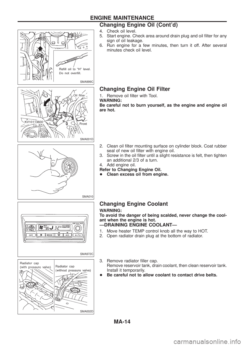
4. Check oil level.
5. Start engine. Check area around drain plug and oil ®lter for any
sign of oil leakage.
6. Run engine for a few minutes, then turn it off. After several
minutes check oil level.
Changing Engine Oil Filter
1. Remove oil ®lter with Tool.
WARNING:
Be careful not to burn yourself, as the engine and engine oil
are hot.
2. Clean oil ®lter mounting surface on cylinder block. Coat rubber
seal of new oil ®lter with engine oil.
3. Screw in the oil ®lter until a slight resistance is felt, then tighten
an additional 2/3 of a turn.
4. Add engine oil.
Refer to Changing Engine Oil.
+Clean excess oil from engine.
Changing Engine Coolant
WARNING:
To avoid the danger of being scalded, never change the cool-
ant when the engine is hot.
ÐDRAINING ENGINE COOLANTÐ
1. Move heater TEMP control knob all the way to HOT.
2. Open radiator drain plug at the bottom of radiator.
3. Remove radiator ®ller cap.
Remove reservoir tank, drain coolant, then clean reservoir tank.
Install it temporarily.
+Be careful not to allow coolant to contact drive belts.
SMA999C
SMA001D
SMA010
SMA972C
SMA002D
ENGINE MAINTENANCE
Changing Engine Oil (Cont'd)
MA-14
Page 994 of 1226
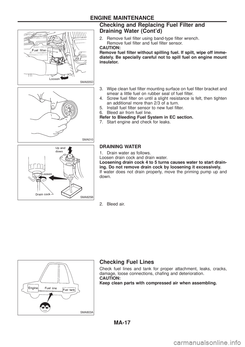
2. Remove fuel ®lter using band-type ®lter wrench.
Remove fuel ®lter and fuel ®lter sensor.
CAUTION:
Remove fuel ®lter without spilling fuel. If spilt, wipe off imme-
diately. Be specially careful not to spill fuel on engine mount
insulator.
3. Wipe clean fuel ®lter mounting surface on fuel ®lter bracket and
smear a little fuel on rubber seal of fuel ®lter.
4. Screw fuel ®lter on until a slight resistance is felt, then tighten
an additional more than 2/3 of a turn.
5. Install fuel ®lter sensor to new fuel ®lter.
6. Bleed air from fuel line.
Refer to Bleeding Fuel System in EC section.
7. Start engine and check for leaks.
DRAINING WATER
1. Drain water as follows.
Loosen drain cock and drain water.
Loosening drain cock 4 to 5 turns causes water to start drain-
ing. Do not remove drain cock by loosening it excessively.
If water does not drain properly, move the priming pump up and
down.
2. Bleed air.
Checking Fuel Lines
Check fuel lines and tank for proper attachment, leaks, cracks,
damage, loose connections, cha®ng and deterioration.
CAUTION:
Keep clean parts with compressed air when assembling.
SMA005D
SMA010
SMA825B
SMA803A
ENGINE MAINTENANCE
Checking and Replacing Fuel Filter and
Draining Water (Cont'd)
MA-17
Page 1000 of 1226
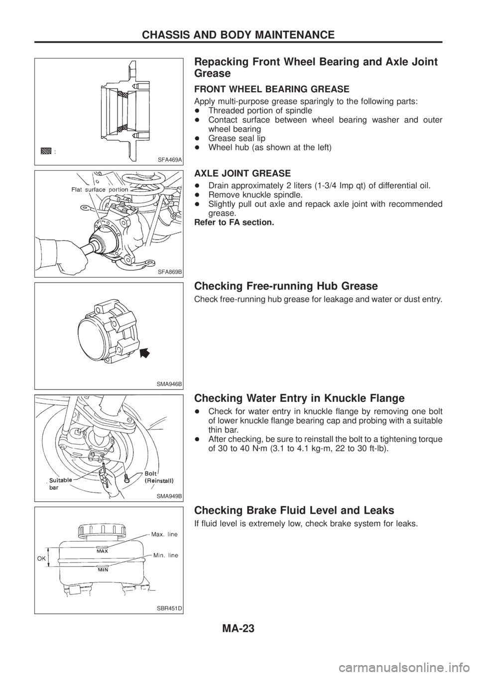
Repacking Front Wheel Bearing and Axle Joint
Grease
FRONT WHEEL BEARING GREASE
Apply multi-purpose grease sparingly to the following parts:
+Threaded portion of spindle
+Contact surface between wheel bearing washer and outer
wheel bearing
+Grease seal lip
+Wheel hub (as shown at the left)
AXLE JOINT GREASE
+Drain approximately 2 liters (1-3/4 Imp qt) of differential oil.
+Remove knuckle spindle.
+Slightly pull out axle and repack axle joint with recommended
grease.
Refer to FA section.
Checking Free-running Hub Grease
Check free-running hub grease for leakage and water or dust entry.
Checking Water Entry in Knuckle Flange
+Check for water entry in knuckle ¯ange by removing one bolt
of lower knuckle ¯ange bearing cap and probing with a suitable
thin bar.
+After checking, be sure to reinstall the bolt to a tightening torque
of 30 to 40 Nzm (3.1 to 4.1 kg-m, 22 to 30 ft-lb).
Checking Brake Fluid Level and Leaks
If ¯uid level is extremely low, check brake system for leaks.
SFA469A
SFA869B
SMA946B
SMA949B
SBR451D
CHASSIS AND BODY MAINTENANCE
MA-23