Page 414 of 1226
Trouble Diagnoses
DAYTIME LIGHT CONTROL UNIT INSPECTION TABLE
Terminal No. ConnectionsINPUT (I)/
OUTPUT (O)Operated conditionVoltage (V)
(Approximate
values)
1Power source for illumi-
nation & tail lampÐÐ12
2Power source for head-
lamp LHÐÐ12
3Power source for head-
lamp RHÐÐ12
4 Headlamp RH OON (daytime light operating*) 12
OFF 0
5 Headlamp LH OON (daytime light operating*) 12
OFF 0
6 Start signal I Ignition switchSTART 12
ON, ACC or OFF 0
7 Power source Ð Ignition switchON or START 12
ACC or OFF 0
8 Alternator ``L'' terminal I EngineRunning 12
Stopped 0
9 Ground Ð Ð Ð
10 Illumination & tail lamp OON (daytime light operating*) 12
OFF 0
11 Lighting switch I1STz2ND position 12
OFF 0
*: Daytime light operating: Lighting switch in ``OFF'' position with engine running.
Bulb Replacement
Refer to ``HEADLAMP'' (EL-63).
Aiming Adjustment
Refer to ``HEADLAMP'' (EL-63).
HEADLAMP Ð Daytime Light System Ð
EL-69
Page 479 of 1226
Electrical Components Inspection
FUEL WARNING LAMP SENSOR CHECK
+It will take a short time for the bulb to light.
NOTE: Inspection for sub fuel warning lamp sensor is the
same as for fuel warning lamp sensor.
OIL PRESSURE SWITCH CHECK
Oil pressure
kPa (bar, kg/cm2, psi)Continuity
Engine startMore than 10 - 20
(0.10 - 0.20, 0.1 - 0.2,1-3)NO
Engine stopLess than 10 - 20
(0.10 - 0.20, 0.1 - 0.2,1-3)YES
Check the continuity between the terminals of oil pressure switch
and body ground.
DIODE CHECK
+Check continuity using an ohmmeter.
+Diode is functioning properly if test results are as shown in the
®gure at left.
NOTE: Speci®cation may vary depending on the type of tester.
Before performing this inspection, be sure to refer to
the instruction manual for the tester to be used.
+Diodes for warning lamps are built into the combination meter
printed circuit.
MEL828F
MEL425F
CEL520
CEL740
WARNING LAMPS
EL-134
Page 480 of 1226

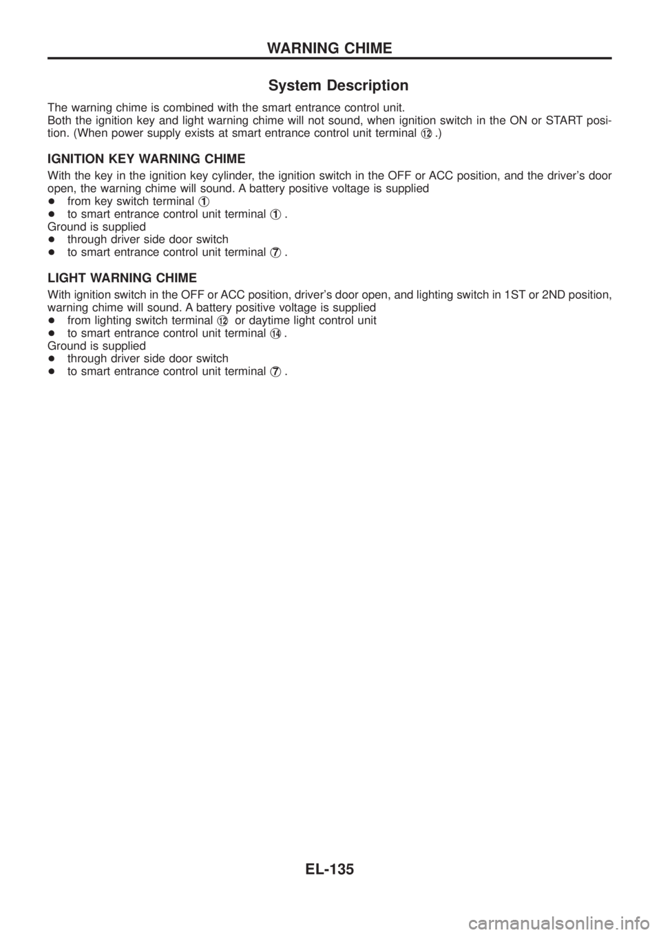
System Description
The warning chime is combined with the smart entrance control unit.
Both the ignition key and light warning chime will not sound, when ignition switch in the ON or START posi-
tion. (When power supply exists at smart entrance control unit terminalj
12.)
IGNITION KEY WARNING CHIME
With the key in the ignition key cylinder, the ignition switch in the OFF or ACC position, and the driver's door
open, the warning chime will sound. A battery positive voltage is supplied
+from key switch terminalj
1
+to smart entrance control unit terminalj1.
Ground is supplied
+through driver side door switch
+to smart entrance control unit terminalj
7.
LIGHT WARNING CHIME
With ignition switch in the OFF or ACC position, driver's door open, and lighting switch in 1ST or 2ND position,
warning chime will sound. A battery positive voltage is supplied
+from lighting switch terminalj
12or daytime light control unit
+to smart entrance control unit terminalj
14.
Ground is supplied
+through driver side door switch
+to smart entrance control unit terminalj
7.
WARNING CHIME
EL-135
Page 483 of 1226
Trouble Diagnoses
SYMPTOM CHART
REFERENCE PAGE EL-138 EL-139 EL-139
SYMPTOM
DIAGNOSTIC PROCEDURE 1
(Lighting switch input signal check)
DIAGNOSTIC PROCEDURE 2
(Key switch input signal check)
DIAGNOSTIC PROCEDURE 3
Light warning chime does not acti-
vate.XX
Ignition key warning chime does not
activate.XX
All warning chimes do not activate.X
DIAGNOSTIC PROCEDURE 1
(Lighting switch input signal check)
CHECK LIGHTING SWITCH INPUT SIG-
NAL.
Check voltage between control unit termi-
nalj
14and ground.
OK
cNG
Check the following.
+7.5A fuse (No.
42,
located in the fuse and
fusible link box) for LHD
models
+Harness for open or
short between control
unit and lighting switch/
daytime light control unit
Go to DIAGNOSTIC PROCEDURE 3.
Condition of lighting
switchVoltage [V]
1ST or 2ND Approx. 12
OFF 0
SEL851UB
.
WARNING CHIME
EL-138
Page 501 of 1226
Wiring Diagram Ð CIGAR Ð
TEL447A
CIGARETTE LIGHTER
EL-156
Page 510 of 1226

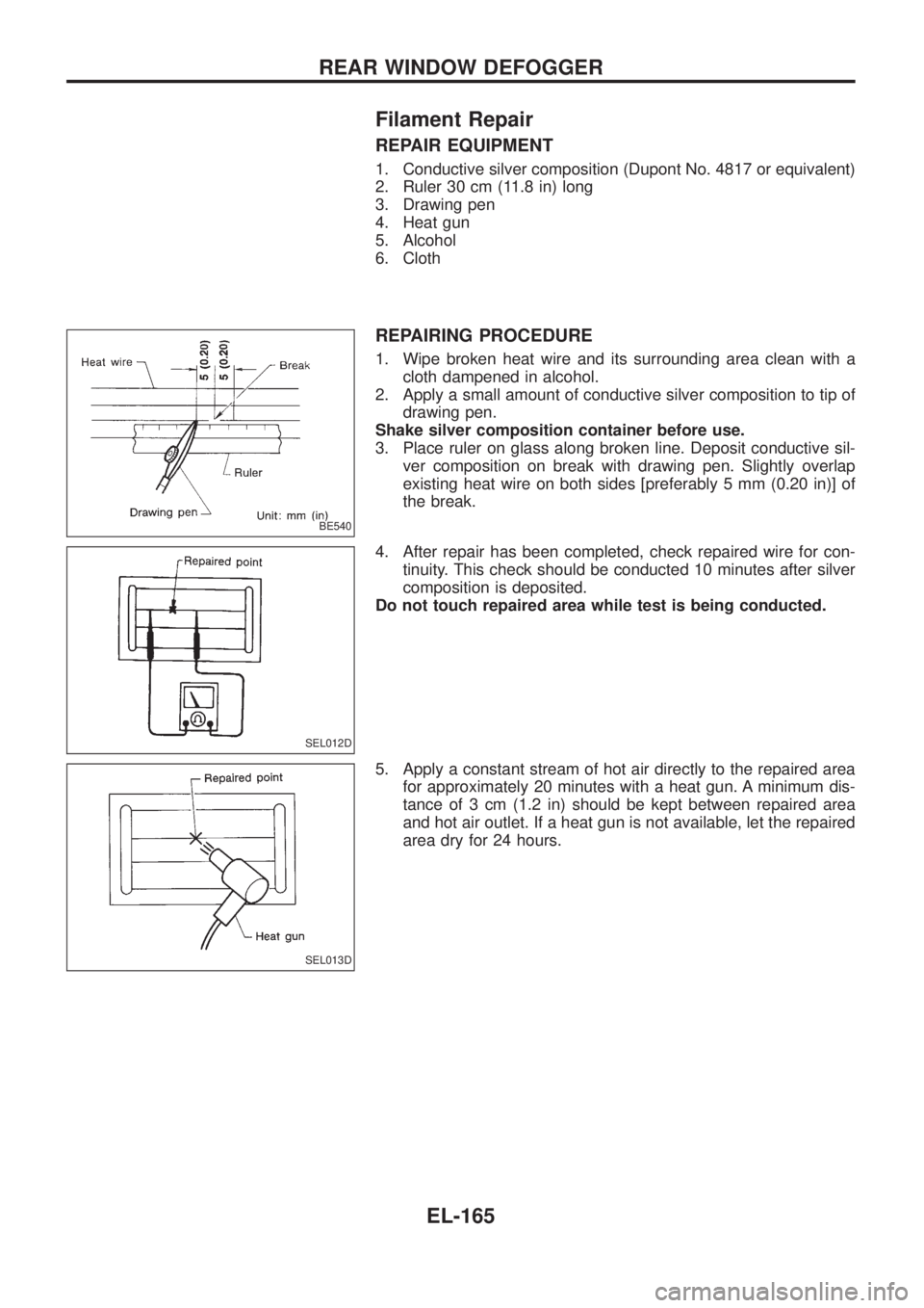
Filament Repair
REPAIR EQUIPMENT
1. Conductive silver composition (Dupont No. 4817 or equivalent)
2. Ruler 30 cm (11.8 in) long
3. Drawing pen
4. Heat gun
5. Alcohol
6. Cloth
REPAIRING PROCEDURE
1. Wipe broken heat wire and its surrounding area clean with a
cloth dampened in alcohol.
2. Apply a small amount of conductive silver composition to tip of
drawing pen.
Shake silver composition container before use.
3. Place ruler on glass along broken line. Deposit conductive sil-
ver composition on break with drawing pen. Slightly overlap
existing heat wire on both sides [preferably 5 mm (0.20 in)] of
the break.
4. After repair has been completed, check repaired wire for con-
tinuity. This check should be conducted 10 minutes after silver
composition is deposited.
Do not touch repaired area while test is being conducted.
5. Apply a constant stream of hot air directly to the repaired area
for approximately 20 minutes with a heat gun. A minimum dis-
tance of 3 cm (1.2 in) should be kept between repaired area
and hot air outlet. If a heat gun is not available, let the repaired
area dry for 24 hours.
BE540
SEL012D
SEL013D
REAR WINDOW DEFOGGER
EL-165
Page 589 of 1226

Trouble Diagnoses
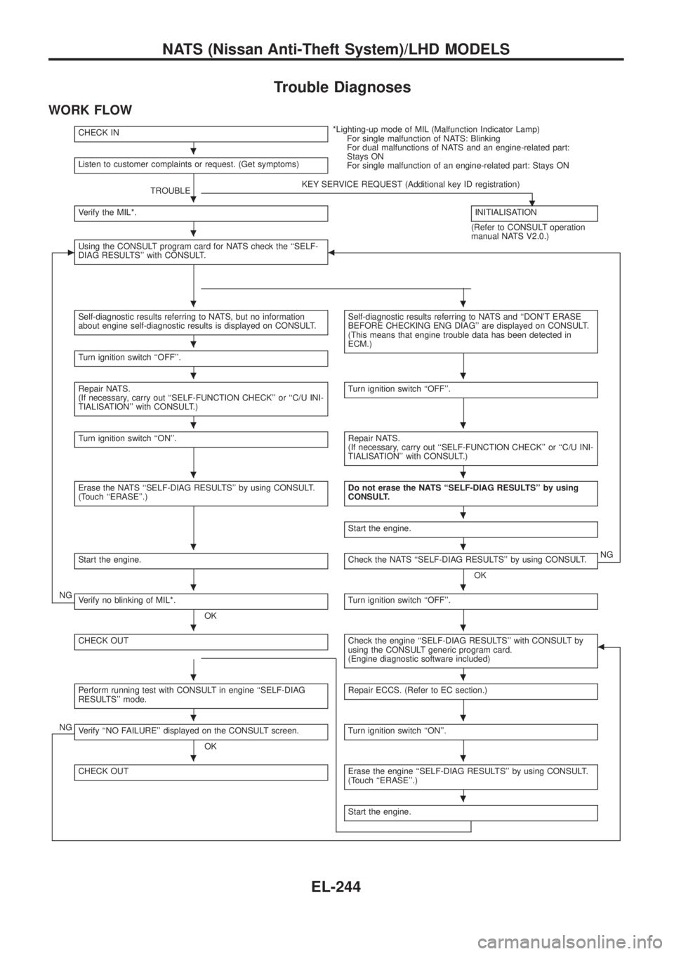
WORK FLOW
CHECK IN*Lighting-up mode of MIL (Malfunction Indicator Lamp)
For single malfunction of NATS: Blinking
For dual malfunctions of NATS and an engine-related part:
Stays ON
For single malfunction of an engine-related part: Stays ON Listen to customer complaints or request. (Get symptoms)
TROUBLEKEY SERVICE REQUEST (Additional key ID registration)
.Verify the MIL*.INITIALISATION
(Refer to CONSULT operation
manual NATS V2.0.)
cUsing the CONSULT program card for NATS check the ``SELF-
DIAG RESULTS'' with CONSULT.b
Self-diagnostic results referring to NATS, but no information
about engine self-diagnostic results is displayed on CONSULT.Self-diagnostic results referring to NATS and ``DON'T ERASE
BEFORE CHECKING ENG DIAG'' are displayed on CONSULT.
(This means that engine trouble data has been detected in
ECM.)
Turn ignition switch ``OFF''.
Repair NATS.
(If necessary, carry out ``SELF-FUNCTION CHECK'' or ``C/U INI-
TIALISATION'' with CONSULT.)Turn ignition switch ``OFF''.
Turn ignition switch ``ON''.Repair NATS.
(If necessary, carry out ``SELF-FUNCTION CHECK'' or ``C/U INI-
TIALISATION'' with CONSULT.)
Erase the NATS ``SELF-DIAG RESULTS'' by using CONSULT.
(Touch ``ERASE''.)Do not erase the NATS ``SELF-DIAG RESULTS'' by using
CONSULT.
Start the engine.
Start the engine.Check the NATS ``SELF-DIAG RESULTS'' by using CONSULT.
OKNG
NGVerify no blinking of MIL*.
OKTurn ignition switch ``OFF''.
CHECK OUTCheck the engine ``SELF-DIAG RESULTS'' with CONSULT by
using the CONSULT generic program card.
(Engine diagnostic software included)b
Perform running test with CONSULT in engine ``SELF-DIAG
RESULTS'' mode.Repair ECCS. (Refer to EC section.)
NGVerify ``NO FAILURE'' displayed on the CONSULT screen.
OKTurn ignition switch ``ON''.
CHECK OUTErase the engine ``SELF-DIAG RESULTS'' by using CONSULT.
(Touch ``ERASE''.)
Start the engine.
.
.
.
..
.
..
..
..
.
..
..
..
..
..
..
.
NATS (Nissan Anti-Theft System)/LHD MODELS
EL-244
Page 590 of 1226

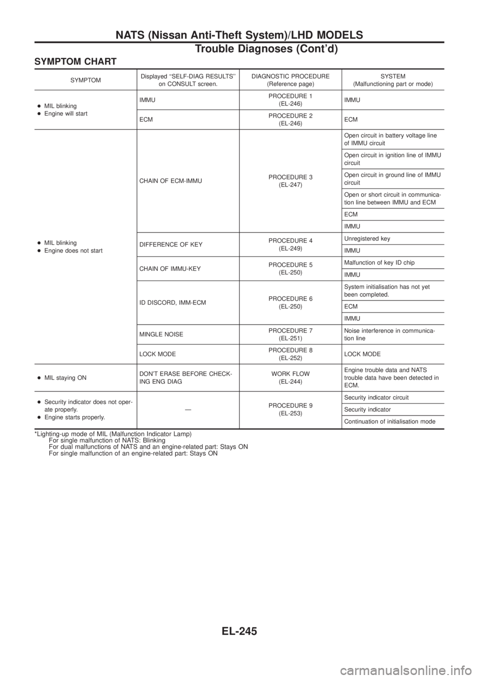
SYMPTOM CHART
SYMPTOMDisplayed ``SELF-DIAG RESULTS''
on CONSULT screen.DIAGNOSTIC PROCEDURE
(Reference page)SYSTEM
(Malfunctioning part or mode)
+MIL blinking
+Engine will startIMMUPROCEDURE 1
(EL-246)IMMU
ECMPROCEDURE 2
(EL-246)ECM
+MIL blinking
+Engine does not startCHAIN OF ECM-IMMUPROCEDURE 3
(EL-247)Open circuit in battery voltage line
of IMMU circuit
Open circuit in ignition line of IMMU
circuit
Open circuit in ground line of IMMU
circuit
Open or short circuit in communica-
tion line between IMMU and ECM
ECM
IMMU
DIFFERENCE OF KEYPROCEDURE 4
(EL-249)Unregistered key
IMMU
CHAIN OF IMMU-KEYPROCEDURE 5
(EL-250)Malfunction of key ID chip
IMMU
ID DISCORD, IMM-ECMPROCEDURE 6
(EL-250)System initialisation has not yet
been completed.
ECM
IMMU
MINGLE NOISEPROCEDURE 7
(EL-251)Noise interference in communica-
tion line
LOCK MODEPROCEDURE 8
(EL-252)LOCK MODE
+MIL staying ONDON'T ERASE BEFORE CHECK-
ING ENG DIAGWORK FLOW
(EL-244)Engine trouble data and NATS
trouble data have been detected in
ECM.
+Security indicator does not oper-
ate properly.
+Engine starts properly.ÐPROCEDURE 9
(EL-253)Security indicator circuit
Security indicator
Continuation of initialisation mode
*Lighting-up mode of MIL (Malfunction Indicator Lamp)
For single malfunction of NATS: Blinking
For dual malfunctions of NATS and an engine-related part: Stays ON
For single malfunction of an engine-related part: Stays ON
NATS (Nissan Anti-Theft System)/LHD MODELS
Trouble Diagnoses (Cont'd)
EL-245