2006 NISSAN PATROL ignition coil
[x] Cancel search: ignition coilPage 53 of 1226

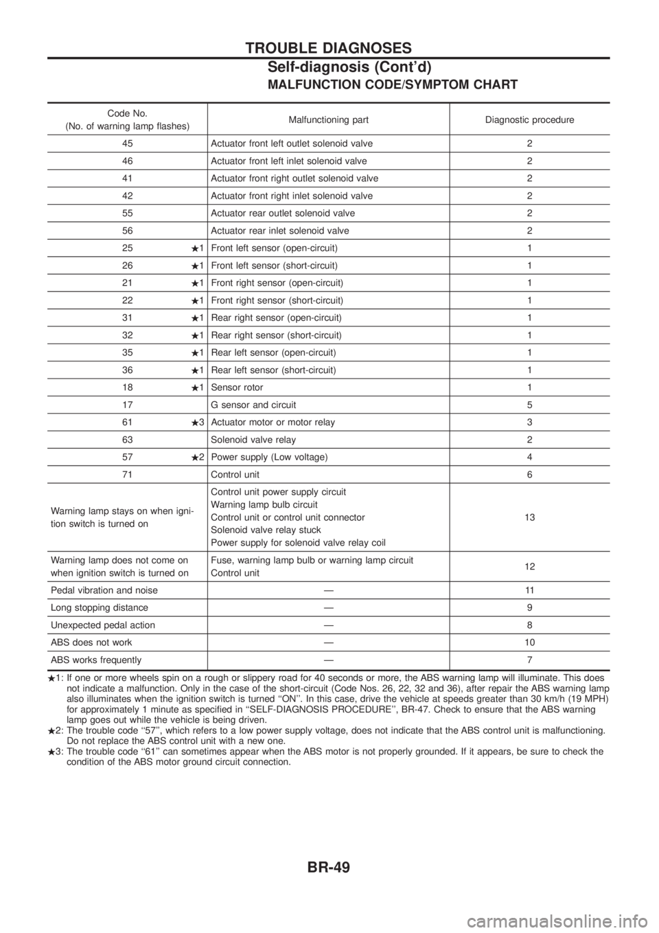
MALFUNCTION CODE/SYMPTOM CHART
Code No.
(No. of warning lamp ¯ashes) Malfunctioning part Diagnostic procedure
45 Actuator front left outlet solenoid valve 2
46 Actuator front left inlet solenoid valve 2
41 Actuator front right outlet solenoid valve 2
42 Actuator front right inlet solenoid valve 2
55 Actuator rear outlet solenoid valve 2
56 Actuator rear inlet solenoid valve 2
25 .1 Front left sensor (open-circuit) 1
26 .1 Front left sensor (short-circuit) 1
21 .1 Front right sensor (open-circuit) 1
22 .1 Front right sensor (short-circuit) 1
31 .1 Rear right sensor (open-circuit) 1
32 .1 Rear right sensor (short-circuit) 1
35 .1 Rear left sensor (open-circuit) 1
36 .1 Rear left sensor (short-circuit) 1
18 .1 Sensor rotor 1
17 G sensor and circuit 5
61 .3 Actuator motor or motor relay 3
63 Solenoid valve relay 2
57 .2 Power supply (Low voltage) 4
71 Control unit 6
Warning lamp stays on when igni-
tion switch is turned on Control unit power supply circuit
Warning lamp bulb circuit
Control unit or control unit connector
Solenoid valve relay stuck
Power supply for solenoid valve relay coil
13
Warning lamp does not come on
when ignition switch is turned on Fuse, warning lamp bulb or warning lamp circuit
Control unit
12
Pedal vibration and noise Ð 11
Long stopping distance Ð 9
Unexpected pedal action Ð 8
ABS does not work Ð 10
ABS works frequently Ð 7
. 1: If one or more wheels spin on a rough or slippery road for 40 seconds or more, the ABS warning lamp will illuminate. This does
not indicate a malfunction. Only in the case of the short-circuit (Code Nos. 26, 22, 32 and 36), after repair the ABS warning lamp
also illuminates when the ignition switch is turned ``ON''. In this case, drive the vehicle at speeds greater than 30 km/h (19 MPH)
for approximately 1 minute as speci®ed in ``SELF-DIAGNOSIS PROCEDURE'', BR-47. Check to ensure that the ABS warning
lamp goes out while the vehicle is being driven.
. 2: The trouble code ``57'', which refers to a low power supply voltage, does not indicate that the ABS control unit is malfunctioning.
Do not replace the ABS control unit with a new one.
. 3: The trouble code ``61'' can sometimes appear when the ABS motor is not properly grounded. If it appears, be sure to check the
condition of the ABS motor ground circuit connection.
TROUBLE DIAGNOSES
Self-diagnosis (Cont'd)
BR-49
Page 247 of 1226

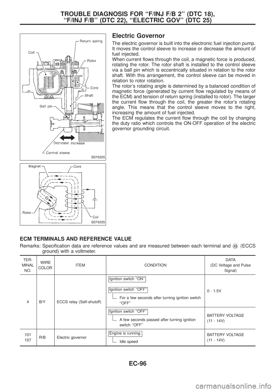
Electric Governor
The electric governor is built into the electronic fuel injection pump.
It moves the control sleeve to increase or decrease the amount of
fuel injected.
When current ¯ows through the coil, a magnetic force is produced,
rotating the rotor. The rotor shaft is installed to the control sleeve
via a ball pin which is eccentrically situated in relation to the rotor
shaft. With this arrangement, the control sleeve can be moved in
relation to rotor rotation.
The rotor's rotating angle is determined by a balanced condition of
magnetic force (generated by current ¯ow regulated by means of
the ECM) and tension of return spring (installed to rotor). The larger
the current ¯ow through the coil, the greater the rotor's rotating
angle. This means that the control sleeve moves to the right,
increasing the amount of fuel injected.
The ECM regulates the current ¯ow through the coil by changing
the duty ratio which controls the ON-OFF operation of the electric
governor grounding circuit.
ECM TERMINALS AND REFERENCE VALUE
Remarks: Speci®cation data are reference values and are measured between each terminal andV43(ECCS
ground) with a voltmeter.
TER-
MINAL
NO.WIRE
COLORITEM CONDITIONDATA
(DC Voltage and Pulse
Signal)
4 B/Y ECCS relay (Self-shutoff)Ignition switch ``ON''
Ignition switch ``OFF''
For a few seconds after turning ignition switch
``OFF''0 - 1.5V
Ignition switch ``OFF''
A few seconds passed after turning ignition
switch ``OFF''BATTERY VOLTAGE
(11 - 14V)
101
107R/B Electric governorEngine is running.
Idle speedBATTERY VOLTAGE
(11 - 14V)
SEF632S
SEF633S
TROUBLE DIAGNOSIS FOR ``F/INJ F/B 2'' (DTC 18),
``F/INJ F/B'' (DTC 22), ``ELECTRIC GOV'' (DTC 25)
EC-96
Page 398 of 1226

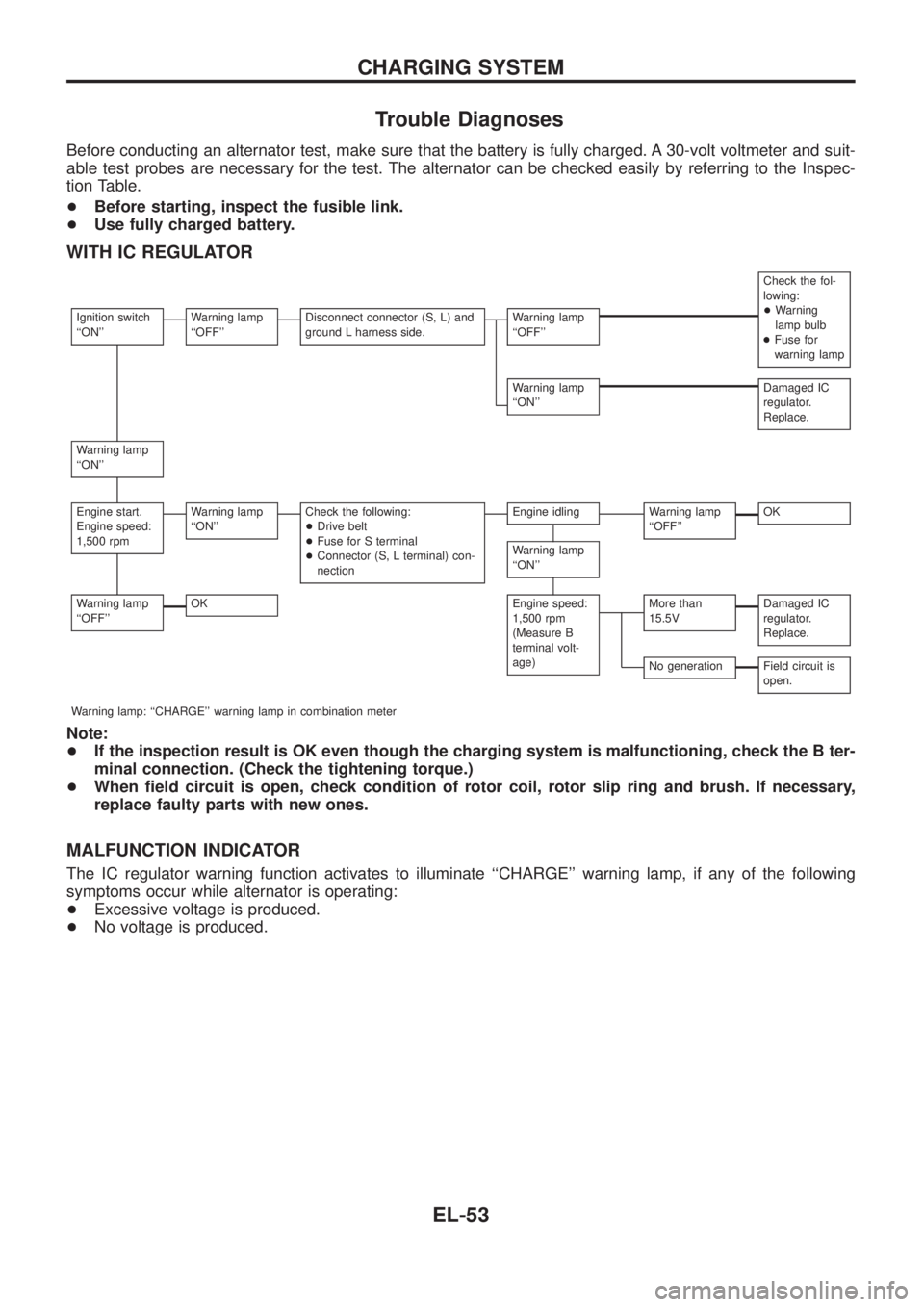
Trouble Diagnoses
Before conducting an alternator test, make sure that the battery is fully charged. A 30-volt voltmeter and suit-
able test probes are necessary for the test. The alternator can be checked easily by referring to the Inspec-
tion Table.
+Before starting, inspect the fusible link.
+Use fully charged battery.
WITH IC REGULATOR
Check the fol-
lowing:
+Warning
lamp bulb
+Fuse for
warning lamp
Ignition switch
``ON''Warning lamp
``OFF''Disconnect connector (S, L) and
ground L harness side.Warning lamp
``OFF''
Warning lamp
``ON''Damaged IC
regulator.
Replace.
Warning lamp
``ON''
Engine start.
Engine speed:
1,500 rpmWarning lamp
``ON''Check the following:
+Drive belt
+Fuse for S terminal
+Connector (S, L terminal) con-
nectionEngine idlingWarning lamp
``OFF''OK
Warning lamp
``ON''
Warning lamp
``OFF''OKEngine speed:
1,500 rpm
(Measure B
terminal volt-
age)More than
15.5VDamaged IC
regulator.
Replace.
No generationField circuit is
open.
Warning lamp: ``CHARGE'' warning lamp in combination meter
Note:
+If the inspection result is OK even though the charging system is malfunctioning, check the B ter-
minal connection. (Check the tightening torque.)
+When ®eld circuit is open, check condition of rotor coil, rotor slip ring and brush. If necessary,
replace faulty parts with new ones.
MALFUNCTION INDICATOR
The IC regulator warning function activates to illuminate ``CHARGE'' warning lamp, if any of the following
symptoms occur while alternator is operating:
+Excessive voltage is produced.
+No voltage is produced.
CHARGING SYSTEM
EL-53
Page 517 of 1226

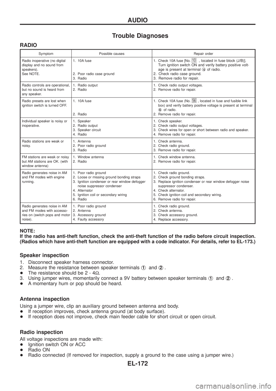
Trouble Diagnoses
RADIO
Symptom Possible causes Repair order
Radio inoperative (no digital
display and no sound from
speakers).
See NOTE.1. 10A fuse
2. Poor radio case ground
3. Radio1. Check 10A fuse [No.
10, located in fuse block (J/B)].
Turn ignition switch ON and verify battery positive volt-
age is present at terminalj
10of radio.
2. Check radio case ground.
3. Remove radio for repair.
Radio controls are operational,
but no sound is heard from
any speaker.1. Radio output
2. Radio1. Check radio output voltages.
2. Remove radio for repair.
Radio presets are lost when
ignition switch is turned OFF.1. 10A fuse
2. Radio1. Check 10A fuse (No.
56, located in fuse and fusible link
box) and verify battery positive voltage is present at terminal
j
6of radio.
2. Remove radio for repair.
Individual speaker is noisy or
inoperative.1. Speaker
2. Radio output
3. Speaker circuit
4. Radio1. Check speaker.
2. Check radio output voltages.
3. Check wires for open or short between radio and speaker.
4. Remove radio for repair.
Radio stations are weak or
noisy.1. Antenna
2. Poor radio ground
3. Radio1. Check antenna.
2. Check radio ground.
3. Remove radio for repair.
FM stations are weak or noisy
but AM stations are OK. (with
window antenna)1. Window antenna
2. Radio1. Check window antenna.
2. Remove radio for repair.
Radio generates noise in AM
and FM modes with engine
running.1. Poor radio ground
2. Loose or missing ground bonding straps
3. Ignition condenser or rear window defogger
noise suppressor condenser
4. Alternator
5. Ignition coil or secondary wiring
6. Radio1. Check radio ground.
2. Check ground bonding straps.
3. Replace ignition condenser or rear window defogger noise
suppressor condenser.
4. Check alternator.
5. Check ignition coil and secondary wiring.
6. Remove radio for repair.
Radio generates noise in AM
and FM modes with accesso-
ries on (switch pops and motor
noise).1. Poor radio ground
2. Antenna
3. Accessory ground
4. Faulty accessory1. Check radio ground.
2. Check antenna.
3. Check accessory ground.
4. Replace accessory.
NOTE:
If the radio has anti-theft function, check the anti-theft function of the radio before circuit inspection.
(Radios which have anti-theft function are equipped with a code indicator. For details, refer to EL-173.)
Speaker inspection
1. Disconnect speaker harness connector.
2. Measure the resistance between speaker terminalsj
1andj2.
+The resistance should be2-4W.
3. Using jumper wires, momentarily connect a 9V battery between speaker terminalsj
1andj2.
+A momentary hum or pop should be heard.
Antenna inspection
Using a jumper wire, clip an auxiliary ground between antenna and body.
+If reception improves, check antenna ground (at body surface).
+If reception does not improve, check main feeder cable for short circuit or open circuit.
Radio inspection
All voltage inspections are made with:
+Ignition switch ON or ACC
+Radio ON
+Radio connected (If removed for inspection, supply a ground to the case using a jumper wire.)
AUDIO
EL-172