2006 NISSAN PATROL key battery
[x] Cancel search: key batteryPage 178 of 1226

Removal
1. Remove battery.
Disconnect electronic injection pump harness connectors.
2. Set No. 1 piston at TDC on its compression stroke.
TDC: Crankshaft pulley notch without painted mark
3. Remove fuel hoses (supply, return and spill) and injection
tubes.
4. Remove air duct and injection pump timing belt cover.
5. Remove injection pump timing belt.
Refer to EM section (``Injection Pump Timing Belt'').
6. Remove injection pump sprocket with Tool.
+Remove key from injection pump shaft and store safely.
SEF663V
SEF664V
SEF665V
ELECTRONIC FUEL INJECTION PUMP
EC-27
Page 185 of 1226
DIAGNOSTIC TEST MODE IÐBULB CHECK
In this mode, the MALFUNCTION INDICATOR LAMP on the instrument panel should stay ON. If it remains
OFF, check the bulb. Refer to EL section (``WARNING LAMPS AND CHIME'') or see EC-188.
DIAGNOSTIC TEST MODE IÐMALFUNCTION WARNING
MALFUNCTION
INDICATOR LAMPCondition
ONWhen the malfunction is detected or the ECM's CPU is malfunctioning. (Refer to ``MIL Illumination'' of the
``DIAGNOSTIC TROUBLE CODE INDEX'', EC-1.)
OFF No malfunction.
+These Diagnostic Trouble Code Numbers are clari®ed in Diagnostic Test Mode II (SELF-DIAGNOSTIC
RESULTS).
DIAGNOSTIC TEST MODE IIÐSELF-DIAGNOSTIC RESULTS
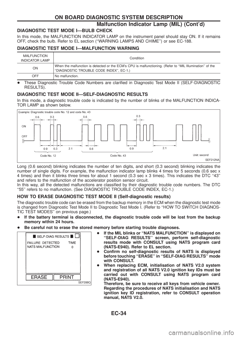
In this mode, a diagnostic trouble code is indicated by the number of blinks of the MALFUNCTION INDICA-
TOR LAMP as shown below.
Long (0.6 second) blinking indicates the number of ten digits, and short (0.3 second) blinking indicates the
number of single digits. For example, the malfunction indicator lamp blinks 4 times for 5 seconds (0.6 sec x
4 times) and then it blinks three times for about 1 second (0.3 sec x 3 times). This indicates the DTC ``43''
and refers to the malfunction of the accelerator position sensor circuit.
In this way, all the detected malfunctions are classi®ed by their diagnostic trouble code numbers. The DTC
``55'' refers to no malfunction. (See DIAGNOSTIC TROUBLE CODE INDEX, EC-1.)
HOW TO ERASE DIAGNOSTIC TEST MODE II (Self-diagnostic results)
The diagnostic trouble code can be erased from the backup memory in the ECM when the diagnostic test mode
is changed from Diagnostic Test Mode II to Diagnostic Test Mode I. (Refer to ``HOW TO SWITCH DIAGNOS-
TIC TEST MODES'' on previous page.)
+If the battery terminal is disconnected, the diagnostic trouble code will be lost from the backup
memory within 24 hours.
+Be careful not to erase the stored memory before starting trouble diagnoses.
+If the MIL blinks or ``NATS MALFUNCTION'' is displayed on
``SELF-DIAG RESULTS'' screen, perform self-diagnostic
results mode with CONSULT using NATS program card
(NATS-E940). Refer to EL section.
+Con®rm no self-diagnostic results of NATS is displayed
before touching ``ERASE'' in ``SELF-DIAG RESULTS'' mode
with CONSULT.
+When replacing ECM, initialisation of NATS V2.0 system
and registration of all NATS V2.0 ignition key IDs must be
carried out with CONSULT using NATS program card
(NATS-E940).
Therefore, be sure to receive all keys from vehicle owner.
Regarding the procedures of NATS initialisation and NATS
ignition key ID registration, refer to CONSULT operation
manual, NATS V2.0.
SEF212NA
SEF288Q
ON BOARD DIAGNOSTIC SYSTEM DESCRIPTION
Malfunction Indicator Lamp (MIL) (Cont'd)
EC-34
Page 445 of 1226
Trouble Diagnoses
DIAGNOSTIC PROCEDURE
SYMPTOM: Front interior room lamp does not turn on when
any door is opened, or timer does not operate
properly.
Does room lamp turn on when room lamp
switch is in ``ON'' position?
Ye s
cNo
Check the following.
+Bulb
+10A fuse [No.
20,
located in the fuse block
(J/B)]
+Harness for open or
short between fuse and
room lamp
+Room lamp ground con-
dition
Does key warning chime operate prop-
erly?
Ye s
cNo
Check ``WARNING
CHIME'' system.
(Refer to EL-135.)
Does power door lock operate using driver
side knob lock switch?
Ye s
cNo
Check ``POWER DOOR
LOCK'' system.
(Refer to EL-204.)
CHECK ROOM LAMP OUTPUT SIGNAL.
1. Turn room lamp switch to ``DOOR''
position.
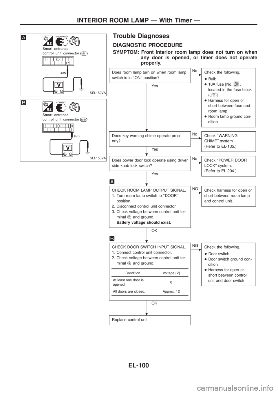
2. Disconnect control unit connector.
3. Check voltage between control unit ter-
minalj
17and ground.
Battery voltage should exist.
OK
cNG
Check harness for open or
short between room lamp
and control unit.
CHECK DOOR SWITCH INPUT SIGNAL.
1. Connect control unit connector.
2. Check voltage between control unit ter-
minalj
10and ground.
OK
cNG
Check the following.
+Door switch
+Door switch ground con-
dition
+Harness for open or
short between control
unit and door switch
Replace control unit.
Condition Voltage [V]
At least one door is
opened.0
All doors are closed. Approx. 12
SEL152VA
SEL153VA
.
.
.
.
.
INTERIOR ROOM LAMP Ð With Timer Ð
EL-100
Page 463 of 1226
Trouble Diagnoses
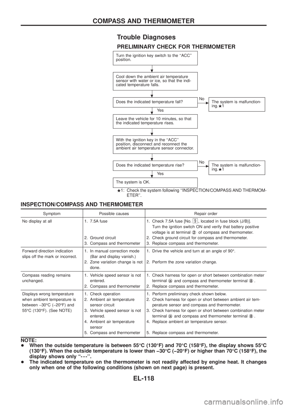
PRELIMINARY CHECK FOR THERMOMETER
Turn the ignition key switch to the ``ACC''
position.
Cool down the ambient air temperature
sensor with water or ice, so that the indi-
cated temperature falls.
Does the indicated temperature fall?
Ye s
cNo
The system is malfunction-
ing..1
Leave the vehicle for 10 minutes, so that
the indicated temperature rises.
With the ignition key in the ``ACC''
position, disconnect and reconnect the
ambient air temperature sensor connector.
Does the indicated temperature rise?
Ye s
cNo
The system is malfunction-
ing..1
The system is OK.
.1: Check the system following ``INSPECTION/COMPASS AND THERMOM-
ETER''.
INSPECTION/COMPASS AND THERMOMETER
Symptom Possible causes Repair order
No display at all 1. 7.5A fuse
2. Ground circuit
3. Compass and thermometer1. Check 7.5A fuse [No.
9, located in fuse block (J/B)].
Turn the ignition switch ON and verify that battery positive
voltage is at terminalj
2of compass and thermometer.
2. Check ground circuit for compass and thermometer.
3. Replace compass and thermometer.
Forward direction indication
slips off the mark or incorrect.1. In manual correction mode
(Bar and display vanish.)
2. Zone variation change is not
done.1. Drive the vehicle and turn at an angle of 90É.
2. Perform the zone variation change.
Compass reading remains
unchanged.1. Vehicle speed sensor is not
entered.
2. Compass and thermometer1. Check harness for open or short between combination meter
terminalj
26and compass and thermometer terminalj8.
2. Replace compass and thermometer.
Displays wrong temperature
when ambient temperature is
between þ30ÉC (þ20ÉF) and
55ÉC (130ÉF). (See NOTE)1. Check operation
2. Ambient air temperature
sensor circuit
3. Vehicle speed sensor is not
entered.
4. Ambient air temperature
sensor
5. Compass and thermometer1. Perform preliminary check shown below.
2. Check harness for open or short between ambient air tem-
perature sensor and compass and thermometer.
3. Check harness for open or short between combination meter
terminalj
26and compass and thermometer terminalj8.
4. Replace ambient air temperature sensor.
5. Replace compass and thermometer.
NOTE:
+When the outside temperature is between 55ÉC (130ÉF) and 70ÉC (158ÉF), the display shows 55ÉC
(130ÉF). When the outside temperature is lower than þ30ÉC (þ20ÉF) or higher than 70ÉC (158ÉF), the
display shows only ``- - -''.
+The indicated temperature on the thermometer is not readily affected by engine heat. It changes
only when one of the following conditions (shown on next page) is present.
.
.
.
.
.
.
COMPASS AND THERMOMETER
EL-118
Page 480 of 1226
System Description
The warning chime is combined with the smart entrance control unit.
Both the ignition key and light warning chime will not sound, when ignition switch in the ON or START posi-
tion. (When power supply exists at smart entrance control unit terminalj
12.)
IGNITION KEY WARNING CHIME
With the key in the ignition key cylinder, the ignition switch in the OFF or ACC position, and the driver's door
open, the warning chime will sound. A battery positive voltage is supplied
+from key switch terminalj
1
+to smart entrance control unit terminalj1.
Ground is supplied
+through driver side door switch
+to smart entrance control unit terminalj
7.
LIGHT WARNING CHIME
With ignition switch in the OFF or ACC position, driver's door open, and lighting switch in 1ST or 2ND position,
warning chime will sound. A battery positive voltage is supplied
+from lighting switch terminalj
12or daytime light control unit
+to smart entrance control unit terminalj
14.
Ground is supplied
+through driver side door switch
+to smart entrance control unit terminalj
7.
WARNING CHIME
EL-135
Page 552 of 1226
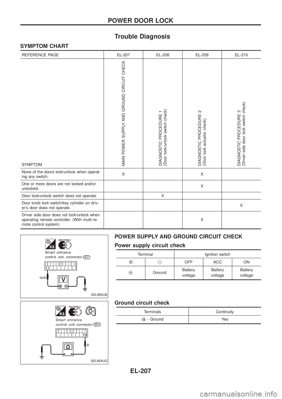
Trouble Diagnosis
SYMPTOM CHART
REFERENCE PAGE EL-207 EL-208 EL-209 EL-210
SYMPTOM
MAIN POWER SUPPLY AND GROUND CIRCUIT CHECK
DIAGNOSTIC PROCEDURE 1
(Door lock/unlock switch check)
DIAGNOSTIC PROCEDURE 2
(Door lock actuator check)
DIAGNOSTIC PROCEDURE 3
(Driver side door lock switch check)
None of the doors lock/unlock when operat-
ing any switch.XX
One or more doors are not locked and/or
unlocked.X
Door lock/unlock switch does not operate. X
Door knob lock switch/key cylinder on driv-
er's door does not operate.X
Driver side door does not lock/unlock when
operating remote controller. (With multi-re-
mote control system)X
POWER SUPPLY AND GROUND CIRCUIT CHECK
Power supply circuit check
Terminal Ignition switch
Å@OFF ACC ON
j
11GroundBattery
voltageBattery
voltageBattery
voltage
Ground circuit check
Terminals Continuity
j
18- Ground Yes
SEL860UB
SEL854UD
POWER DOOR LOCK
EL-207
Page 558 of 1226
Power door lock/unlock operation by lock knob
+With lock knob on driver or passenger door setting to LOCK while all doors are closed will lock all doors.
When one or more door is opened, with lock knob on passenger door setting to LOCK will lock
passenger door only. (Power door lock system will not operate.)
+With lock knob on driver or passenger door setting to UNLOCK while all doors are closed will unlock all
doors.
Lock knob operation cannot control super lock.
Key reminder system
+If the ignition key is in the ignition key cylinder and any door is open, setting lock/unlock switch or lock
knob on driver or passenger door to ``LOCK'' locks the door once but then immediately unlocks all doors.
System initialisation
+System initialisation is required when battery cables are reconnected. Conduct one of the followings to
release super lock once;
Ð insert the key into ignition key cylinder and turn it to ON.
Ð LOCK/UNLOCK operation using door key cylinder.
POWER DOOR LOCK Ð Super Lock Ð
System Description (Cont'd)
EL-213
Page 577 of 1226
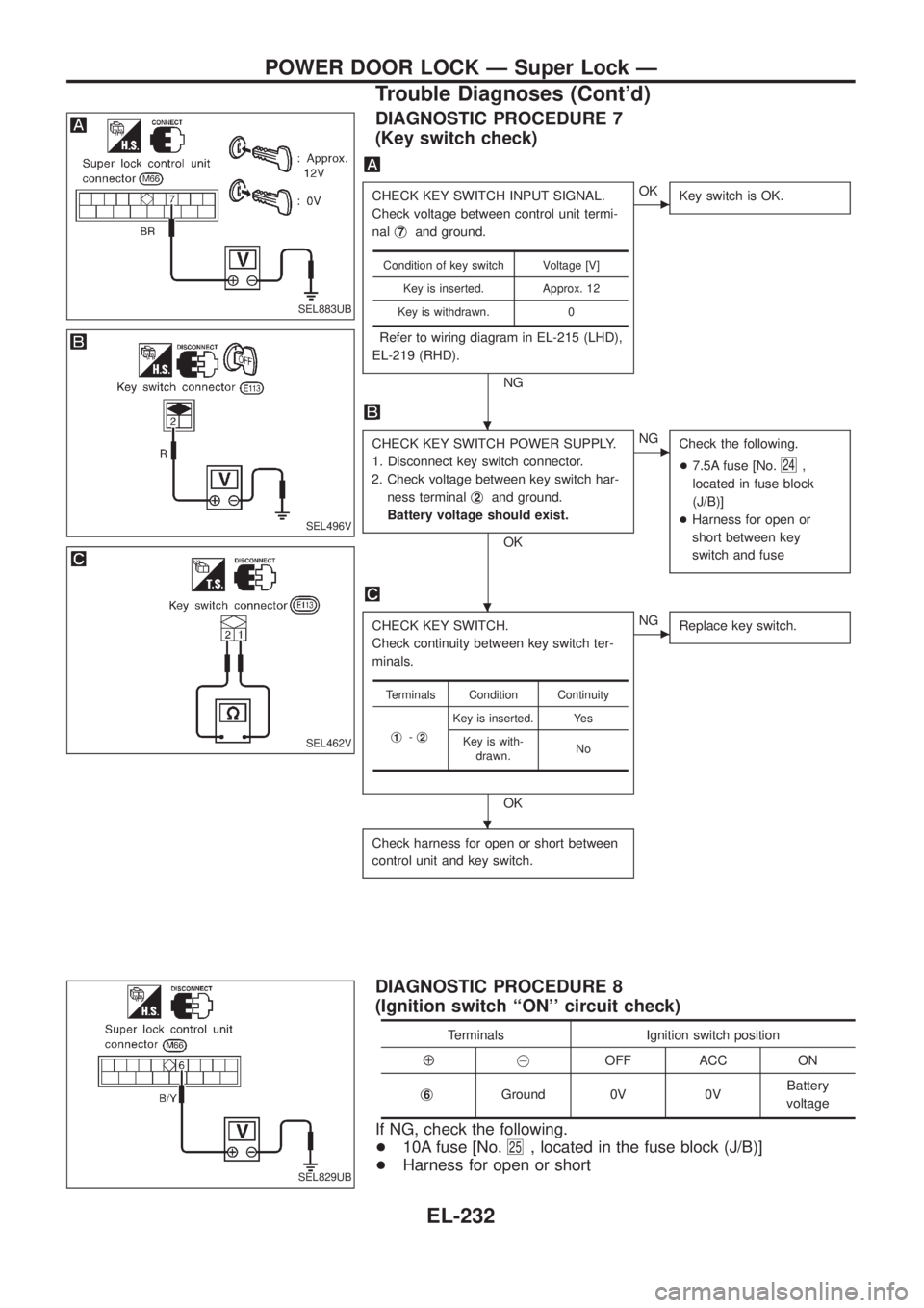
DIAGNOSTIC PROCEDURE 7
(Key switch check)
CHECK KEY SWITCH INPUT SIGNAL.
Check voltage between control unit termi-
nalj
7and ground.
Refer to wiring diagram in EL-215 (LHD),
EL-219 (RHD).
NG
cOK
Key switch is OK.
CHECK KEY SWITCH POWER SUPPLY.
1. Disconnect key switch connector.
2. Check voltage between key switch har-
ness terminalj
2and ground.
Battery voltage should exist.
OK
cNG
Check the following.
+7.5A fuse [No.
24,
located in fuse block
(J/B)]
+Harness for open or
short between key
switch and fuse
CHECK KEY SWITCH.
Check continuity between key switch ter-
minals.
OK
cNG
Replace key switch.
Check harness for open or short between
control unit and key switch.
Condition of key switch Voltage [V]
Key is inserted. Approx. 12
Key is withdrawn. 0
Terminals Condition Continuity
j
1-j2
Key is inserted. Yes
Key is with-
drawn.No
DIAGNOSTIC PROCEDURE 8
(Ignition switch ``ON'' circuit check)
Terminals Ignition switch position
Å@OFF ACC ON
j
6Ground 0V 0VBattery
voltage
If NG, check the following.
+10A fuse [No.
25, located in the fuse block (J/B)]
+Harness for open or short
SEL883UB
SEL496V
SEL462V
SEL829UB
.
.
.
POWER DOOR LOCK Ð Super Lock Ð
Trouble Diagnoses (Cont'd)
EL-232