2006 NISSAN PATROL air suspension
[x] Cancel search: air suspensionPage 1 of 1226

Edition: February 1998
Release: February 1998 (01)
Publication No.: SM8E-0Y61E0E
Reference No.: 7711346063GENERAL INFORMATIONGI
MAINTENANCEMA
ENGINE MECHANICALEM
ENGINE LUBRICATION &
COOLING SYSTEMSLC
ENGINE CONTROL SYSTEMEC
ACCELERATOR CONTROL,
FUEL & EXHAUST SYSTEMFE
CLUTCHCL
MANUAL TRANSMISSIONMT
AUTOMATIC TRANSMISSIONAT
TRANSFERTF
PROPELLER SHAFT &
DIFFERENTIAL CARRIERPD
FRONT AXLE & FRONT SUSPENSIONFA
REAR AXLE & REAR SUSPENSIONRA
BRAKE SYSTEMBR
STEERING SYSTEMST
RESTRAINT SYSTEMRS
BODY & TRIMBT
HEATER & AIR CONDITIONERHA
ELECTRICAL SYSTEMEL
ALPHABETICAL INDEXIDX
PATROL GR
MODEL Y61 SERIES
NISSAN EUROPE S.A.S.
1998 NISSAN EUROPE S.A.S.
Produced in The Netherlands
Not to be reproduced in whole or in part
without the prior written permission of
Nissan Europe S.A.S., Paris, France.
QUICK REFERENCE INDEX
Page 6 of 1226
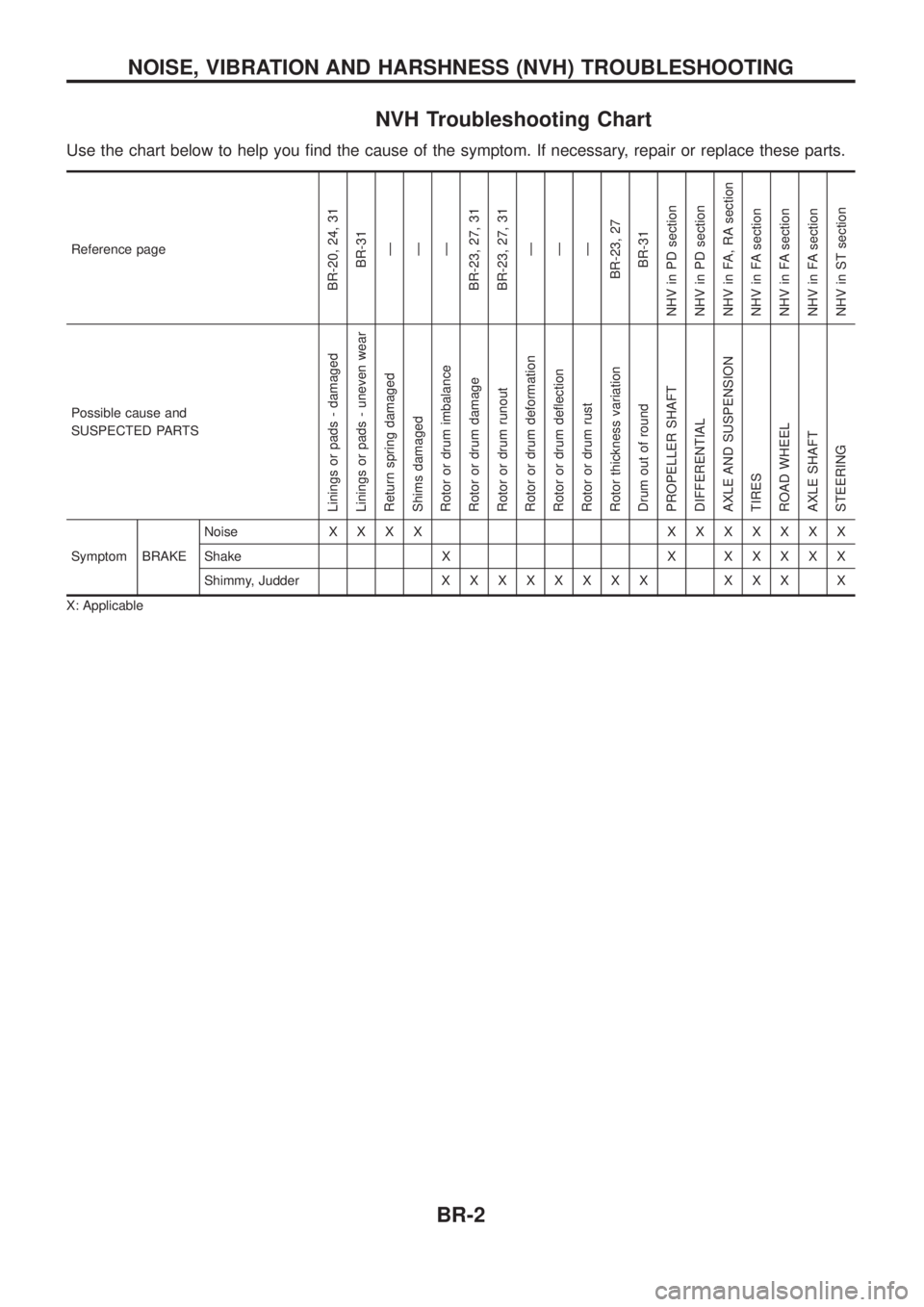
NVH Troubleshooting Chart
Use the chart below to help you ®nd the cause of the symptom. If necessary, repair or replace these parts.
Reference page
BR-20, 24, 31BR-31Ð
Ð
Ð
BR-23, 27, 31
BR-23, 27, 31 Ð
Ð
Ð
BR-23, 27 BR-31
NHV in PD section
NHV in PD section
NHV in FA, RA section
NHV in FA section
NHV in FA section
NHV in FA section
NHV in ST section
Possible cause and
SUSPECTED PARTS
Linings or pads - damaged
Linings or pads - uneven wear
Return spring damaged
Shims damaged
Rotor or drum imbalance
Rotor or drum damage
Rotor or drum runout
Rotor or drum deformation
Rotor or drum de¯ection
Rotor or drum rust
Rotor thickness variation
Drum out of round
PROPELLER SHAFT
DIFFERENTIAL
AXLE AND SUSPENSION
TIRES
ROAD WHEEL
AXLE SHAFT
STEERING
Symptom BRAKE Noise
XXXX XXXXXXX
Shake X X X X X X X
Shimmy, Judder X X XXXXXX XXX X
X: Applicable
NOISE, VIBRATION AND HARSHNESS (NVH) TROUBLESHOOTING
BR-2
Page 11 of 1226

1. Ensure vehicle is unladen condition*.* Fuel, radiator coolant and engine oil full. Spare tire, jack,hand tools and mats in designated positions.
2. Have a driver sit in the driver's seat and one person sit on the rear end. Then have the person on the rear end slowly get off
the vehicle. This is necessary to stabilize suspension de¯ec-
tion.
3. Gradually depress brake pedal and attach a lever to the stop- per bolt, then adjust length ``L'' as follows:Length ``L'': Approx. 175.2 - 178.2 mm (6.90 - 7.02 in)
4. Remove front LH tire.
5. Connect tool to air bleeders on front LH brake caliper and rear LH or RH brake wheel cylinder.
6. Install front LH tire.
Before installing front LH tire, con®rm the tool is not touching
the front LH wheel.
7. Bleed air from Tool.
8. Raise front brake pressure to 4,904 kPa (49.0 bar, 50 kg/cm
2,
711 psi) and 9,807 kPa (98.1 bar, 100 kg/cm2, 1,422 psi) and
check rear brake pressure. Rear brake pressure: Refer to table on next page.
SBR287E
SBR822BA
SBR823BA
SBR377D
BRAKE HYDRAULIC LINE/CONTROL VALVE
Load Sensing Valve (Cont'd)
BR-7
Page 345 of 1226
BULB SPECIFICATIONS............................................314
Headlamp.................................................................314
Exterior Lamp ..........................................................314
Interior Lamp............................................................314
WIRING DIAGRAM CODES (CELL CODES) .............315
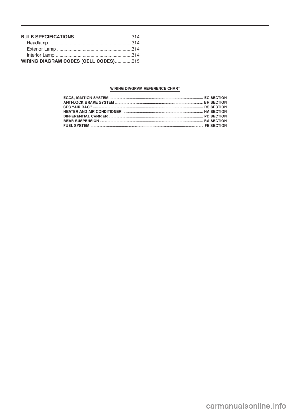
WIRING DIAGRAM REFERENCE CHART
ECCS, IGNITION SYSTEM ........................................................................\
................... EC SECTION
ANTI-LOCK BRAKE SYSTEM ........................................................................\
.............. BR SECTION
SRS ``AIR BAG'' ........................................................................\
.................................... RS SECT ION
HEATER AND AIR CONDITIONER ........................................................................\
...... HA SECTION
DIFFERENTIAL CARRIER ........................................................................\
.................... PD SECTION
REAR SUSPENSION ........................................................................\
............................. RA SECTION
FUEL SYSTEM ........................................................................\
....................................... FE SECT ION
Page 736 of 1226
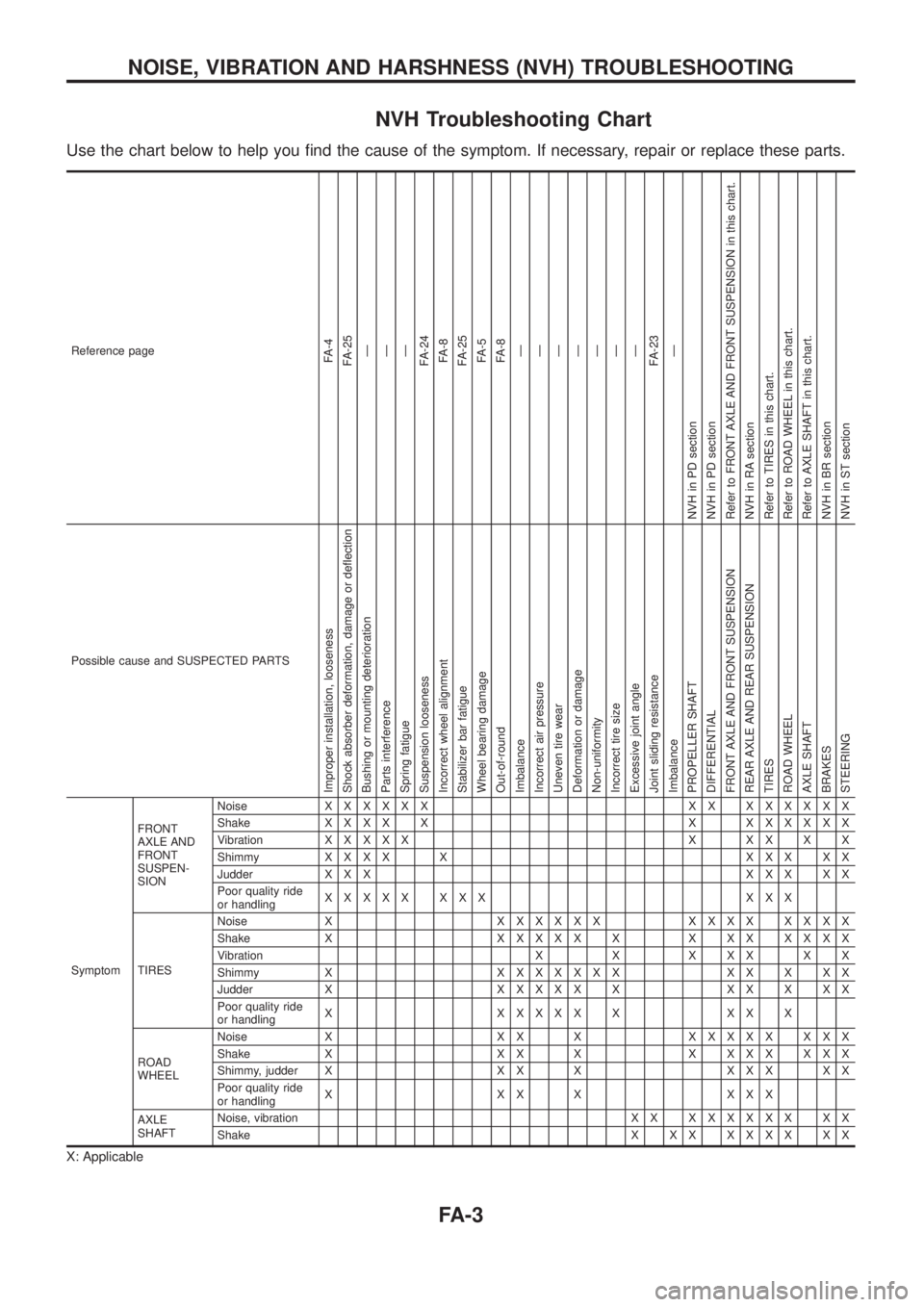
NVH Troubleshooting Chart
Use the chart below to help you ®nd the cause of the symptom. If necessary, repair or replace these parts.
Reference pageFA-4
FA-25
Ð
Ð
Ð
FA-24
FA-8
FA-25
FA-5
FA-8
Ð
Ð
Ð
Ð
Ð
Ð
Ð
FA-23
Ð
NVH in PD section
NVH in PD section
Refer to FRONT AXLE AND FRONT SUSPENSION in this chart.
NVH in RA section
Refer to TIRES in this chart.
Refer to ROAD WHEEL in this chart.
Refer to AXLE SHAFT in this chart.
NVH in BR section
NVH in ST section
Possible cause and SUSPECTED PARTS
Improper installation, looseness
Shock absorber deformation, damage or de¯ection
Bushing or mounting deterioration
Parts interference
Spring fatigue
Suspension looseness
Incorrect wheel alignment
Stabilizer bar fatigue
Wheel bearing damage
Out-of-round
Imbalance
Incorrect air pressure
Uneven tire wear
Deformation or damage
Non-uniformity
Incorrect tire size
Excessive joint angle
Joint sliding resistance
Imbalance
PROPELLER SHAFT
DIFFERENTIAL
FRONT AXLE AND FRONT SUSPENSION
REAR AXLE AND REAR SUSPENSION
TIRES
ROAD WHEEL
AXLE SHAFT
BRAKES
STEERING
SymptomFRONT
AXLE AND
FRONT
SUSPEN-
SIONNoiseXXXXXX XX XXXXXX
ShakeXXXX X X XXXXXX
VibrationXXXXX X XX X X
ShimmyXXXX X XXX XX
Judder X X XXXX XX
Poor quality ride
or handlingXXXXX XXX XXX
TIRESNoise XXXXXXX XXXX XXXX
Shake XXXXXX X X XX XXXX
Vibration X X X X X X X
Shimmy XXXXXXXX XX X XX
Judder XXXXXX X XX X XX
Poor quality ride
or handlingX XXXXX X XX X
ROAD
WHEELNoise X X X XXXXXX XXX
Shake X X X X X X X X X X X
Shimmy, judder X X X X X X X X X
Poor quality ride
or handlingX XX X XXX
AXLE
SHAFTNoise, vibration X XXXXXXX XX
ShakeX XX XXXX XX
X: Applicable
NOISE, VIBRATION AND HARSHNESS (NVH) TROUBLESHOOTING
FA-3
Page 758 of 1226
Shock Absorber
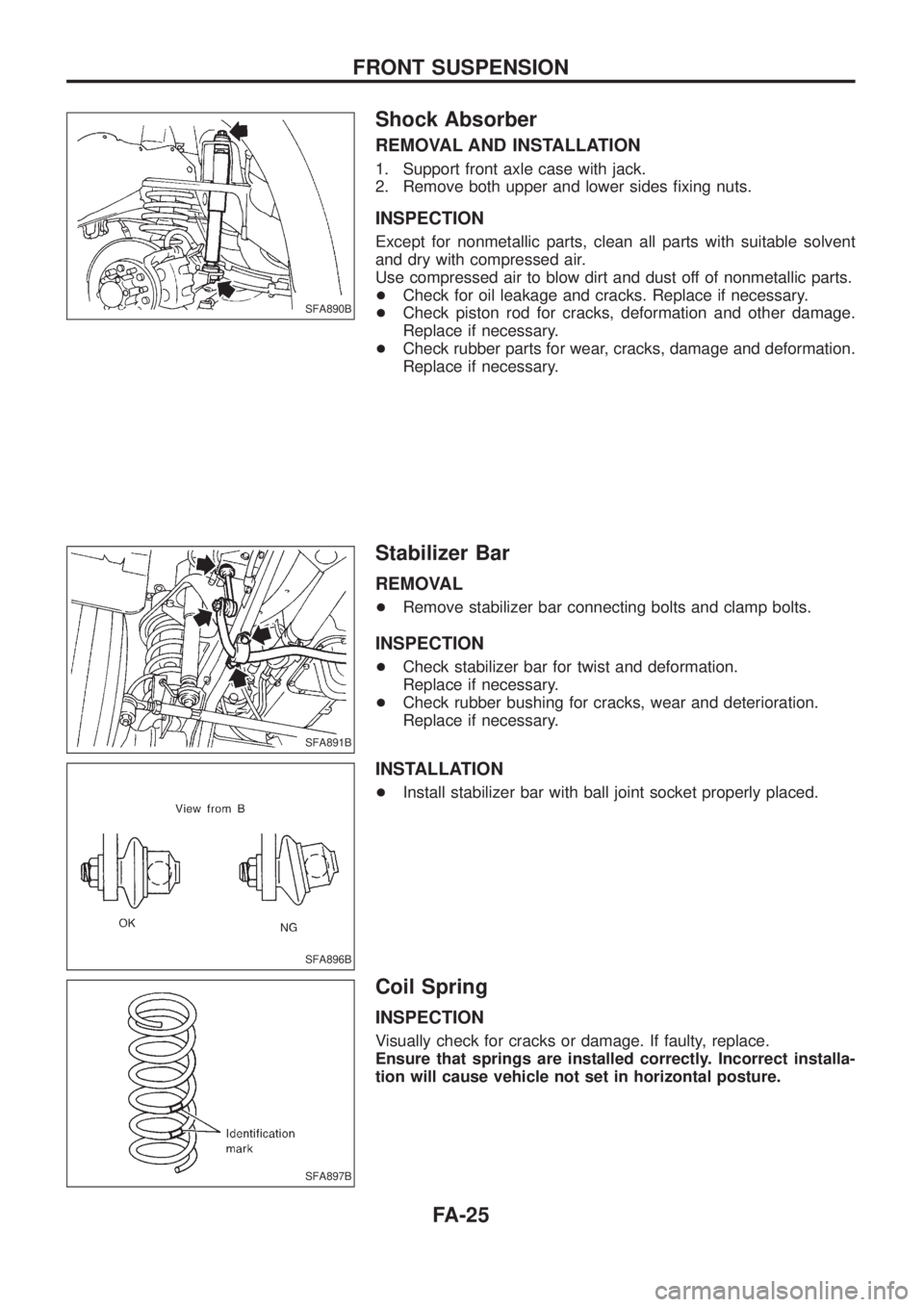
REMOVAL AND INSTALLATION
1. Support front axle case with jack.
2. Remove both upper and lower sides ®xing nuts.
INSPECTION
Except for nonmetallic parts, clean all parts with suitable solvent
and dry with compressed air.
Use compressed air to blow dirt and dust off of nonmetallic parts.
+Check for oil leakage and cracks. Replace if necessary.
+Check piston rod for cracks, deformation and other damage.
Replace if necessary.
+Check rubber parts for wear, cracks, damage and deformation.
Replace if necessary.
Stabilizer Bar
REMOVAL
+Remove stabilizer bar connecting bolts and clamp bolts.
INSPECTION
+Check stabilizer bar for twist and deformation.
Replace if necessary.
+Check rubber bushing for cracks, wear and deterioration.
Replace if necessary.
INSTALLATION
+Install stabilizer bar with ball joint socket properly placed.
Coil Spring
INSPECTION
Visually check for cracks or damage. If faulty, replace.
Ensure that springs are installed correctly. Incorrect installa-
tion will cause vehicle not set in horizontal posture.
SFA890B
SFA891B
SFA896B
SFA897B
FRONT SUSPENSION
FA-25
Page 951 of 1226

Front drive shaft (Transfer) .............................TF-11
Front ®nal drive disassembly (4WD) ..............PD-14
Front ®nal drive removal and installa-
tion (4WD)...................................................PD-11
Front passenger air bag.............................RS-8, 14
Front seat belt ..................................................RS-2
Front seat ........................................................BT-32
Front suspension ............................................FA-24
Front washer .................................................EL-141
Front wiper ....................................................EL-141
Fuel cut control (at no load & high
engine speed) .............................................EC-20
Fuel cut solenoid valve ................................EC-129
Fuel ®ller lid.......................................................BT-6
Fuel ®lter replacement ...................................MA-16
Fuel gauge ....................................................EL-102
Fuel injection system......................................EC-15
Fuel line inspection ........................................MA-17
Fuel precautions ................................................GI-5
Fuel temperature sensor ..............................EC-134
Fuse block.....................................................EL-319
Fuse ................................................................EL-14
Fusible link ......................................................EL-14
G
GLOW - Wiring diagram...............................EC-150
GOVNR - Wiring diagram ..............................EC-95
Garage jack and safety stand .........................GI-39
Gauges..........................................................EL-102
Gear components (M/T) .................................MT-10
Glass .................................................................BT-9
Glow plug .............................................EC-150, 154
Glow relay ............................................EC-150, 154
Grease .............................................................MA-9
Ground distribution..........................................EL-15
H
H/AIM - Wiring diagram ..................................EL-71
H/LAMP - Wiring diagram ...............................EL-61
HEAT UP - Wiring diagram ..........................EC-182
HFC134a (R134a) system service
procedure ..................................................HA-112
HLC - Wiring diagram ...................................EL-153
HORN - Wiring diagram................................EL-155
Harness connector inspection .........................GI-17
Harness connector ............................................EL-2
Harness layout ..............................................EL-275
Headlamp aiming control ................................EL-70
Headlamp leveler - See Headlamp
aiming control ..............................................EL-70
Headlamp wiper ............................................EL-153
Headlamp ........................................................EL-61
Headlining - See Roof trim .............................BT-20
Heat up switch..............................................EC-182
Heated seat.....................................................BT-34Hood..................................................................BT-4
Horn ..............................................................EL-155
How to erase DTC for ECCS OBD
system ........................................................EC-30
I
IATS - Wiring diagram ..................................EC-121
IC/FAN - Wiring diagram ..............................EC-177
ILL - Wiring diagram .......................................EL-87
INT/L - Wiring diagram..................................EL-101
Identi®cation plate............................................GI-37
Idle speed inspection .....................................MA-19
Idle speed .......................................................EC-46
Illumination ......................................................EL-86
In vehicle sensor ..........................................HA-105
Injection nozzle inspection .............................MA-18
Injection nozzle...............................................EC-22
Injection timing control valve ........................EC-100
Instrument panel .............................................BT-11
Intake door control linkage adjustment ..........HA-84
Intake door motor ...........................................HA-25
Intake sensor ................................................HA-111
Interior lamp ....................................................EL-93
Interior .............................................................BT-14
J
Jacking points ..................................................GI-39
Joint connector (J/C).....................................EL-322
Journal bearing assembly (propeller
shaft) .............................................................PD-8
Journal bearing disassembly (propeller
shaft) .............................................................PD-7
Junction box (J/B) .........................................EL-319
L
LSV (Load sensing valve) ................................BR-6
Lifting points ....................................................GI-40
Limited slip diff. adjustment............................PD-23
Limited slip diff. assembly ..............................PD-24
Limited slip diff. disassembly .........................PD-21
Limited slip diff. inspection .............................PD-21
Location of electrical units ............................EL-269
Lock, door .........................................................BT-9
Lubricant (R134a) A/C ..................................HA-114
Lubricants.........................................................MA-9
Lubrication circuit (engine) ...............................LC-3
Lubrication-locks, hinges and hood
latches ........................................................MA-27
Luggage compartment trim .............................BT-14
Luggage room lamp ........................................EL-93
ALPHABETICAL INDEX
IDX-4
Page 979 of 1226
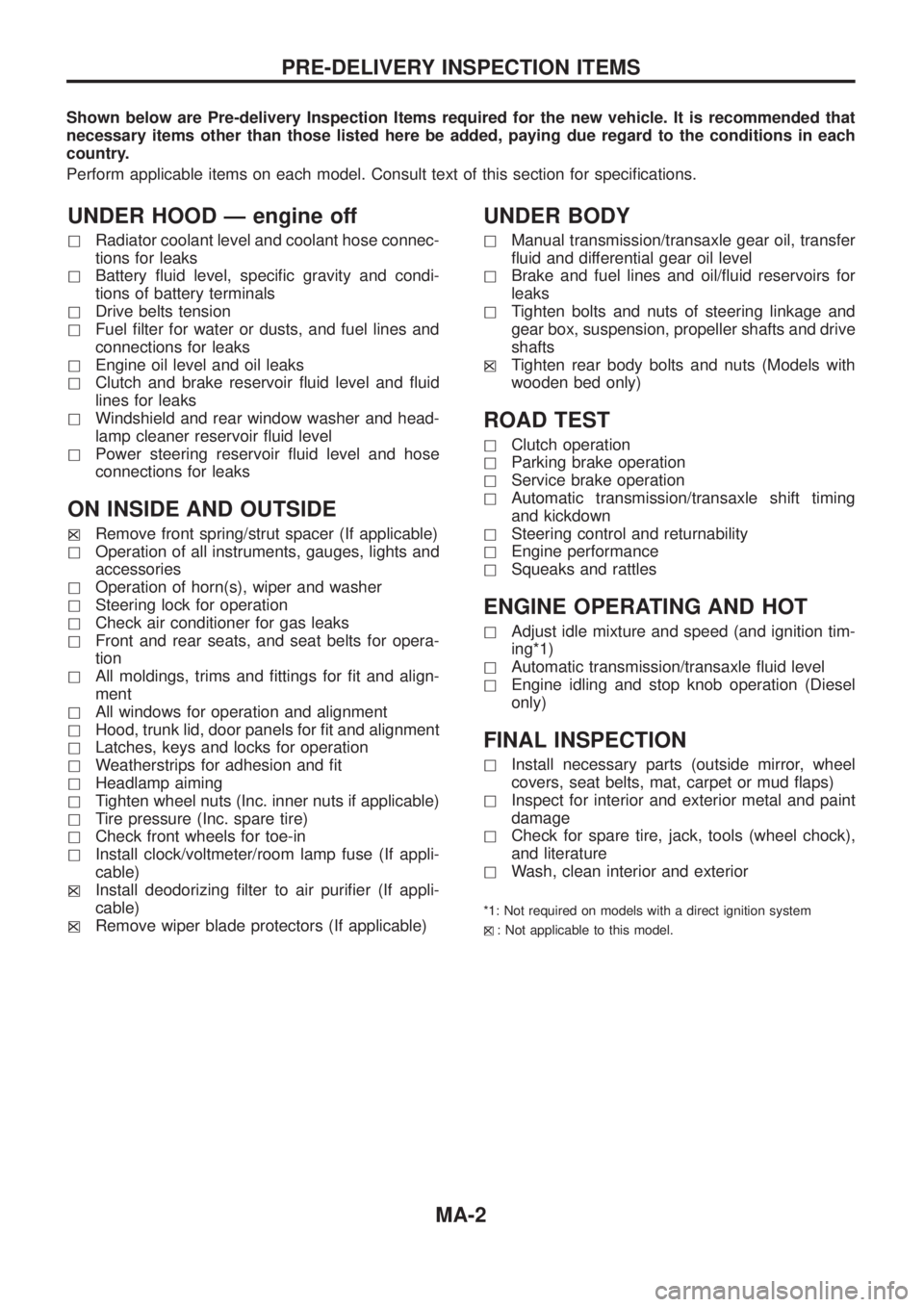
Shown below are Pre-delivery Inspection Items required for the new vehicle. It is recommended that
necessary items other than those listed here be added, paying due regard to the conditions in each
country.
Perform applicable items on each model. Consult text of this section for speci®cations.
UNDER HOOD Ð engine off
hRadiator coolant level and coolant hose connec-
tions for leaks
hBattery ¯uid level, speci®c gravity and condi-
tions of battery terminals
hDrive belts tension
hFuel ®lter for water or dusts, and fuel lines and
connections for leaks
hEngine oil level and oil leaks
hClutch and brake reservoir ¯uid level and ¯uid
lines for leaks
hWindshield and rear window washer and head-
lamp cleaner reservoir ¯uid level
hPower steering reservoir ¯uid level and hose
connections for leaks
ON INSIDE AND OUTSIDE
hXRemove front spring/strut spacer (If applicable)
hOperation of all instruments, gauges, lights and
accessories
hOperation of horn(s), wiper and washer
hSteering lock for operation
hCheck air conditioner for gas leaks
hFront and rear seats, and seat belts for opera-
tion
hAll moldings, trims and ®ttings for ®t and align-
ment
hAll windows for operation and alignment
hHood, trunk lid, door panels for ®t and alignment
hLatches, keys and locks for operation
hWeatherstrips for adhesion and ®t
hHeadlamp aiming
hTighten wheel nuts (Inc. inner nuts if applicable)
hTire pressure (Inc. spare tire)
hCheck front wheels for toe-in
hInstall clock/voltmeter/room lamp fuse (If appli-
cable)
h
XInstall deodorizing ®lter to air puri®er (If appli-
cable)
h
XRemove wiper blade protectors (If applicable)
UNDER BODY
hManual transmission/transaxle gear oil, transfer
¯uid and differential gear oil level
hBrake and fuel lines and oil/¯uid reservoirs for
leaks
hTighten bolts and nuts of steering linkage and
gear box, suspension, propeller shafts and drive
shafts
h
XTighten rear body bolts and nuts (Models with
wooden bed only)
ROAD TEST
hClutch operation
hParking brake operation
hService brake operation
hAutomatic transmission/transaxle shift timing
and kickdown
hSteering control and returnability
hEngine performance
hSqueaks and rattles
ENGINE OPERATING AND HOT
hAdjust idle mixture and speed (and ignition tim-
ing*1)
hAutomatic transmission/transaxle ¯uid level
hEngine idling and stop knob operation (Diesel
only)
FINAL INSPECTION
hInstall necessary parts (outside mirror, wheel
covers, seat belts, mat, carpet or mud ¯aps)
hInspect for interior and exterior metal and paint
damage
hCheck for spare tire, jack, tools (wheel chock),
and literature
hWash, clean interior and exterior
*1: Not required on models with a direct ignition system
h
X: Not applicable to this model.
PRE-DELIVERY INSPECTION ITEMS
MA-2