2006 NISSAN PATROL steering wheel adjustment
[x] Cancel search: steering wheel adjustmentPage 760 of 1226
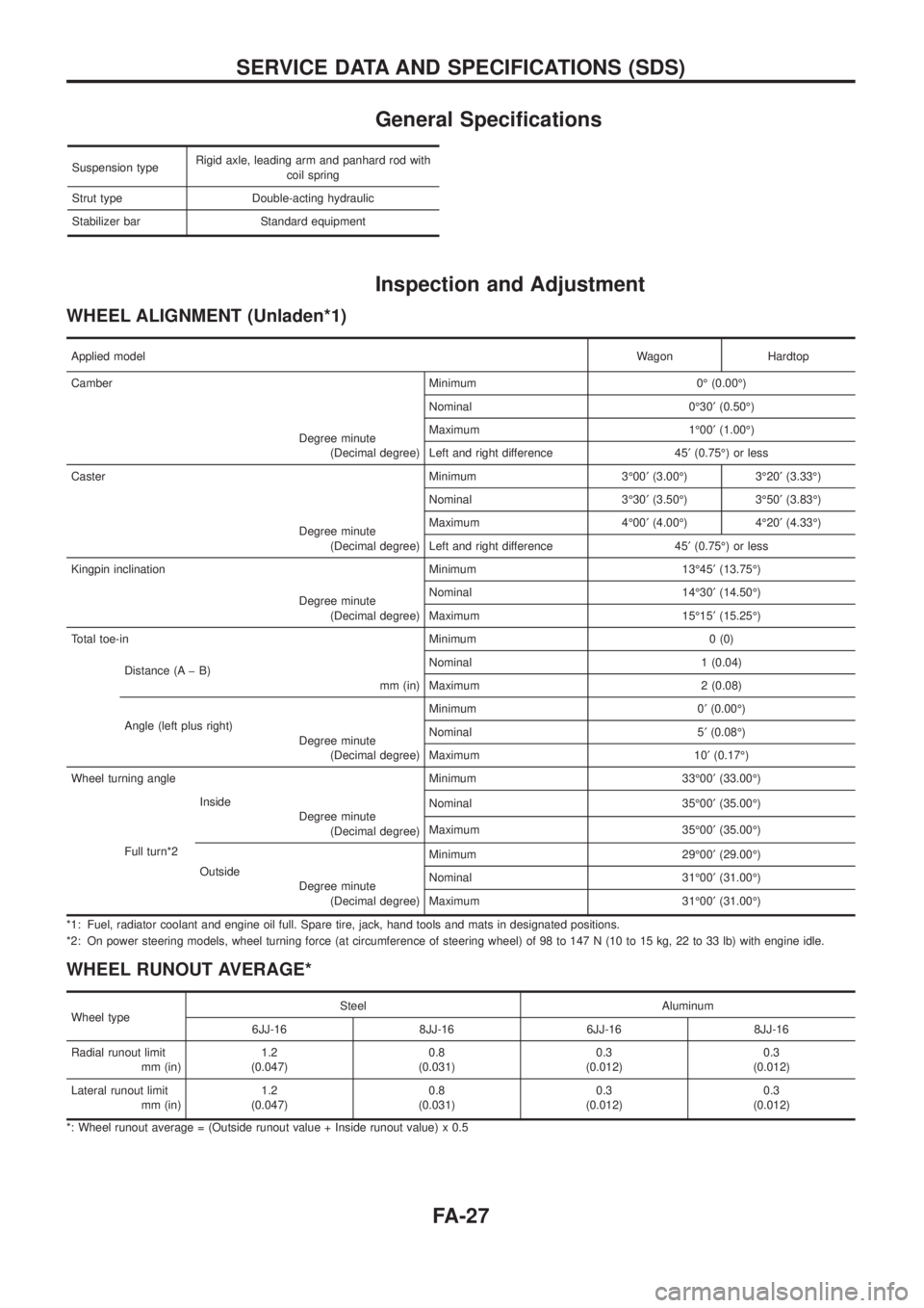
General Speci®cations
Suspension typeRigid axle, leading arm and panhard rod with
coil spring
Strut type Double-acting hydraulic
Stabilizer bar Standard equipment
Inspection and Adjustment
WHEEL ALIGNMENT (Unladen*1)
Applied modelWagon Hardtop
Camber Minimum 0É (0.00É)
Degree minute
(Decimal degree)Nominal 0É30¢(0.50É)
Maximum 1É00¢(1.00É)
Left and right difference 45¢(0.75É) or less
Caster Minimum 3É00¢(3.00É) 3É20¢(3.33É)
Degree minute
(Decimal degree)Nominal 3É30¢(3.50É) 3É50¢(3.83É)
Maximum 4É00¢(4.00É) 4É20¢(4.33É)
Left and right difference 45¢(0.75É) or less
Kingpin inclination Minimum 13É45¢(13.75É)
Degree minute
(Decimal degree)Nominal 14É30¢(14.50É)
Maximum 15É15¢(15.25É)
Total toe-in Minimum 0 (0)
Distance (A þ B)
mm (in)Nominal 1 (0.04)
Maximum 2 (0.08)
Angle (left plus right)
Degree minute
(Decimal degree)Minimum 0¢(0.00É)
Nominal 5¢(0.08É)
Maximum 10¢(0.17É)
Wheel turning angle Minimum 33É00¢(33.00É)
Full turn*2Inside
Degree minute
(Decimal degree)Nominal 35É00¢(35.00É)
Maximum 35É00¢(35.00É)
Outside
Degree minute
(Decimal degree)Minimum 29É00¢(29.00É)
Nominal 31É00¢(31.00É)
Maximum 31É00¢(31.00É)
*1: Fuel, radiator coolant and engine oil full. Spare tire, jack, hand tools and mats in designated positions.
*2: On power steering models, wheel turning force (at circumference of steering wheel) of 98 to 147 N (10 to 15 kg, 22 to 33 lb) with engine idle.
WHEEL RUNOUT AVERAGE*
Wheel typeSteel Aluminum
6JJ-16 8JJ-16 6JJ-16 8JJ-16
Radial runout limit
mm (in)1.2
(0.047)0.8
(0.031)0.3
(0.012)0.3
(0.012)
Lateral runout limit
mm (in)1.2
(0.047)0.8
(0.031)0.3
(0.012)0.3
(0.012)
*: Wheel runout average = (Outside runout value + Inside runout value) x 0.5
SERVICE DATA AND SPECIFICATIONS (SDS)
FA-27
Page 780 of 1226
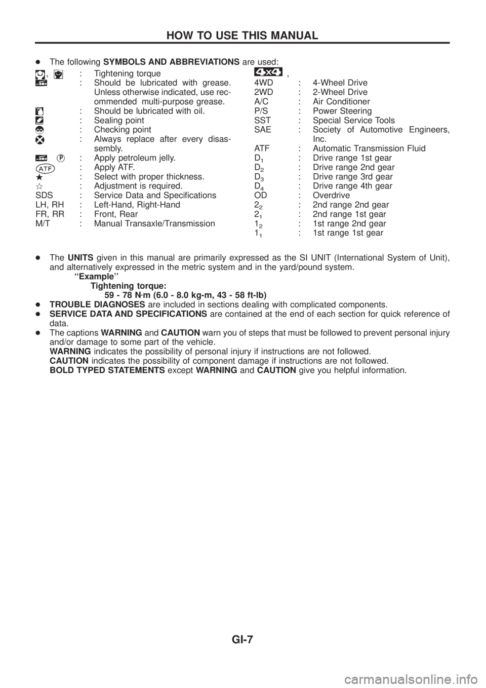
+The followingSYMBOLS AND ABBREVIATIONSare used:
,: Tightening torque
: Should be lubricated with grease.
Unless otherwise indicated, use rec-
ommended multi-purpose grease.
: Should be lubricated with oil.
: Sealing point
: Checking point
: Always replace after every disas-
sembly.
jP: Apply petroleum jelly.
: Apply ATF.
.: Select with proper thickness.
>: Adjustment is required.
SDS : Service Data and Speci®cations
LH, RH : Left-Hand, Right-Hand
FR, RR : Front, Rear
M/T : Manual Transaxle/Transmission
,
4WD : 4-Wheel Drive
2WD : 2-Wheel Drive
A/C : Air Conditioner
P/S : Power Steering
SST : Special Service Tools
SAE : Society of Automotive Engineers,
Inc.
ATF : Automatic Transmission Fluid
D
1: Drive range 1st gear
D
2: Drive range 2nd gear
D
3: Drive range 3rd gear
D
4: Drive range 4th gear
OD : Overdrive
2
2: 2nd range 2nd gear
2
1: 2nd range 1st gear
1
2: 1st range 2nd gear
1
1: 1st range 1st gear
+TheUNITSgiven in this manual are primarily expressed as the SI UNIT (International System of Unit),
and alternatively expressed in the metric system and in the yard/pound system.
``Example''
Tightening torque:
59-78Nzm (6.0 - 8.0 kg-m, 43 - 58 ft-lb)
+TROUBLE DIAGNOSESare included in sections dealing with complicated components.
+SERVICE DATA AND SPECIFICATIONSare contained at the end of each section for quick reference of
data.
+The captionsWARNINGandCAUTIONwarn you of steps that must be followed to prevent personal injury
and/or damage to some part of the vehicle.
WARNINGindicates the possibility of personal injury if instructions are not followed.
CAUTIONindicates the possibility of component damage if instructions are not followed.
BOLD TYPED STATEMENTSexceptWARNINGandCAUTIONgive you helpful information.
HOW TO USE THIS MANUAL
GI-7
Page 983 of 1226
![NISSAN PATROL 2006 Service Manual Chassis and Body Services
Annual driving distance below 30,000 km (18,000 miles)
Abbreviations: R = Replace, I = Inspect, and correct or replace as necessary, L = Lubricate,T=Tighten.
[ ]: At the spec NISSAN PATROL 2006 Service Manual Chassis and Body Services
Annual driving distance below 30,000 km (18,000 miles)
Abbreviations: R = Replace, I = Inspect, and correct or replace as necessary, L = Lubricate,T=Tighten.
[ ]: At the spec](/manual-img/5/57368/w960_57368-982.png)
Chassis and Body Services
Annual driving distance below 30,000 km (18,000 miles)
Abbreviations: R = Replace, I = Inspect, and correct or replace as necessary, L = Lubricate,T=Tighten.
[ ]: At the speci®ed mileage only
MAINTENANCE OPERATIONMAINTENANCE INTERVAL
Reference
page Perform either at number of kilometers (miles) or months,
whichever comes ®rst.km x 1,000 10 20 30 40 50 60 70 80 90
(Miles x 1,000) (6) (12) (18) (24) (30) (36) (42) (48) (54)
Months 6 12 18 24 30 36 42 48 54
CHASSIS AND BODY Underhood and under vehicle
Brake & clutch ¯uid (For level & leaks).I I I I MA-23, 20
Brake ¯uid.R R MA-24
Brake booster vacuum hoses, connections & check valve I I MA-24
Power steering ¯uid & lines (For level & leaks) I I I I MA-26
Brake & clutch systemsI I I I MA-24, 20
Manual transmission oil (For leaks) I I I I MA-20
Manual transmission oil[R] MA-20
Transfer ¯uidI I R I MA-21
Limited slip differential (LSD) gear oil (For level & leaks).*1 I I R I MA-22
Steering gear & linkage, axle & suspension parts, propeller shaft & exhaust system.I I I I MA-26, 20 *2
Greasing points of propeller shaftLLLLMA-21
Drive shafts & steering damper.IIII *3
Body mounting bolts & nutsTTTT *4
Outside and Inside
Wheel alignment (If necessary, rotate & balance wheels) I I I I MA-25, *5
Brake pads, discs & other brake components.I I I I MA-24
Front wheel bearing grease I R I R MA-22
Axle joint in knuckle ¯angeL L MA-23
Free running hub greaseI I I I MA-23
Headlamp aimingIIII *6
Foot brake, parking brake & clutch (For free play, stroke & operation) I I I I *7
Ventilation air ®lterRRR*8
Body corrosionAnnually MA-28
Air bag systemSee NOTE (1) *9
NOTE: (1) Inspect after 10 years, then every 2 years.
(2) Maintenance items with ``.'' should be performed more frequently according to ``Maintenance Under Severe Driv-
ing Conditions''.
*1: Including differential gear with differential lock
*2: ``Front Axle and Front Suspension Parts'' in FA section, ``Rear Axle and Rear Suspension Parts'' in RA section
*3: ``FRONT AXLE Ð Drive Shaft'' in FA section
*4: ``CAB BODY'' in BT section
*5: ``Front Wheel Alignment'' in FA section
*6: ``Aiming Adjustment'' in EL section
*7: ``Brake Pedal and Bracket'' in BR section, ``Adjusting Clutch Pedal'' in CL section
*8: ``Ventilation air ®lter'' in HA section
*9: ``Maintenance Items'' in RS section
PERIODIC MAINTENANCE
MA-6
Page 984 of 1226
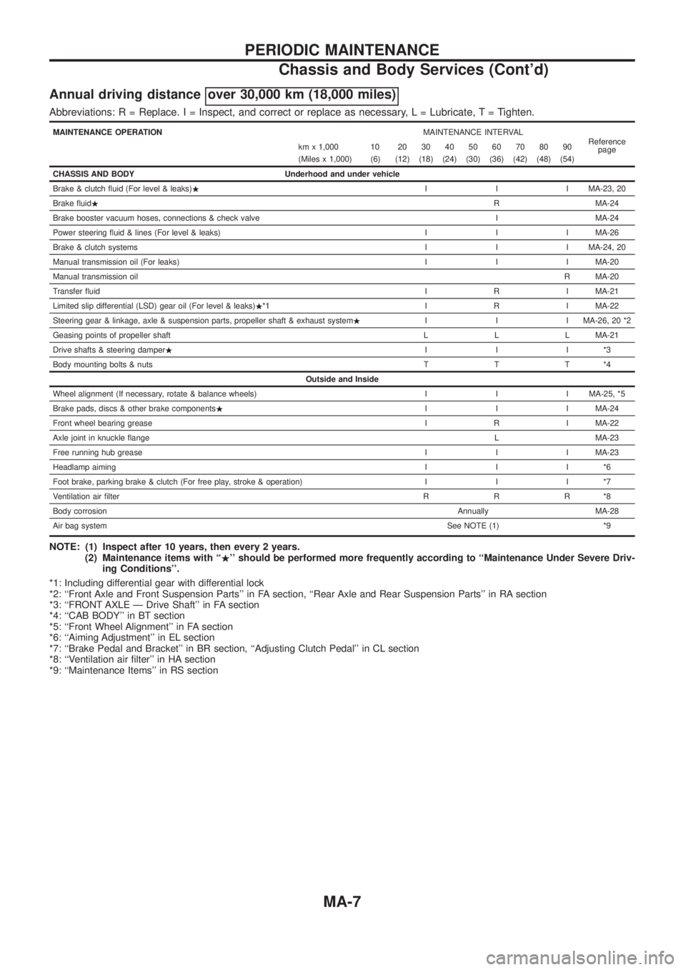
Annual driving distance over 30,000 km (18,000 miles)
Abbreviations: R = Replace. I = Inspect, and correct or replace as necessary, L = Lubricate,T=Tighten.
MAINTENANCE OPERATIONMAINTENANCE INTERVAL
Reference
page km x 1,000 10 20 30 40 50 60 70 80 90
(Miles x 1,000) (6) (12) (18) (24) (30) (36) (42) (48) (54)
CHASSIS AND BODY Underhood and under vehicle
Brake & clutch ¯uid (For level & leaks).I I I MA-23, 20
Brake ¯uid.R MA-24
Brake booster vacuum hoses, connections & check valve I MA-24
Power steering ¯uid & lines (For level & leaks) I I I MA-26
Brake & clutch systemsI I I MA-24, 20
Manual transmission oil (For leaks) I I I MA-20
Manual transmission oilR MA-20
Transfer ¯uidI R I MA-21
Limited slip differential (LSD) gear oil (For level & leaks).*1 I R I MA-22
Steering gear & linkage, axle & suspension parts, propeller shaft & exhaust system.I I I MA-26, 20 *2
Geasing points of propeller shaft L L L MA-21
Drive shafts & steering damper.III*3
Body mounting bolts & nutsTTT*4
Outside and Inside
Wheel alignment (If necessary, rotate & balance wheels) I I I MA-25, *5
Brake pads, discs & other brake components.I I I MA-24
Front wheel bearing greaseI R I MA-22
Axle joint in knuckle ¯angeL MA-23
Free running hub greaseI I I MA-23
Headlamp aimingIII*6
Foot brake, parking brake & clutch (For free play, stroke & operation) I I I *7
Ventilation air ®lterRRR*8
Body corrosionAnnually MA-28
Air bag systemSee NOTE (1) *9
NOTE: (1) Inspect after 10 years, then every 2 years.
(2) Maintenance items with ``.'' should be performed more frequently according to ``Maintenance Under Severe Driv-
ing Conditions''.
*1: Including differential gear with differential lock
*2: ``Front Axle and Front Suspension Parts'' in FA section, ``Rear Axle and Rear Suspension Parts'' in RA section
*3: ``FRONT AXLE Ð Drive Shaft'' in FA section
*4: ``CAB BODY'' in BT section
*5: ``Front Wheel Alignment'' in FA section
*6: ``Aiming Adjustment'' in EL section
*7: ``Brake Pedal and Bracket'' in BR section, ``Adjusting Clutch Pedal'' in CL section
*8: ``Ventilation air ®lter'' in HA section
*9: ``Maintenance Items'' in RS section
PERIODIC MAINTENANCE
Chassis and Body Services (Cont'd)
MA-7
Page 1006 of 1226
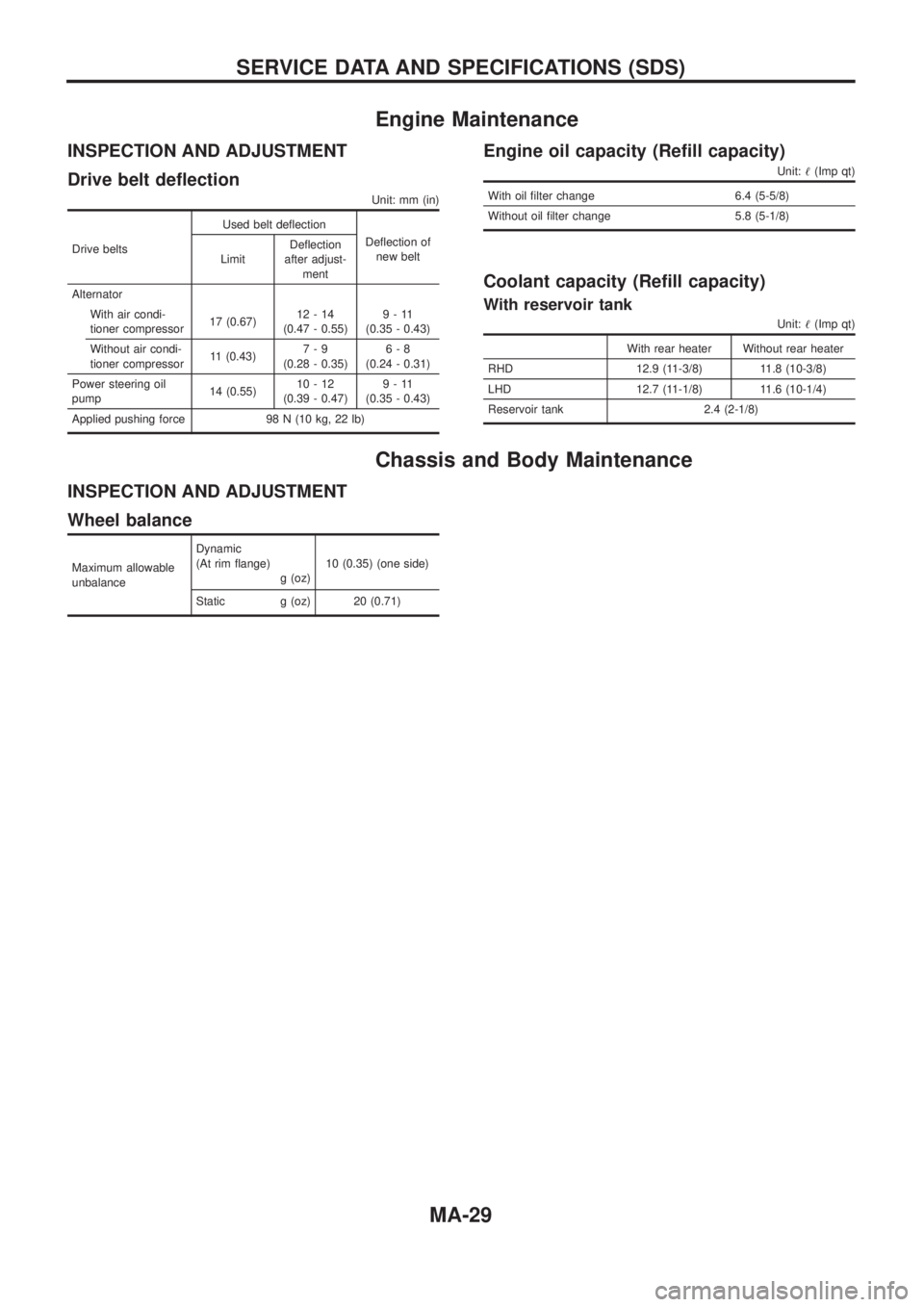
Engine Maintenance
INSPECTION AND ADJUSTMENT
Drive belt de¯ection
Unit: mm (in)
Drive beltsUsed belt de¯ection
De¯ection of
new belt
LimitDe¯ection
after adjust-
ment
Alternator
With air condi-
tioner compressor17 (0.67)12-14
(0.47 - 0.55)9-11
(0.35 - 0.43)
Without air condi-
tioner compressor11 (0.43)7-9
(0.28 - 0.35)6-8
(0.24 - 0.31)
Power steering oil
pump14 (0.55)10-12
(0.39 - 0.47)9-11
(0.35 - 0.43)
Applied pushing force 98 N (10 kg, 22 lb)
Engine oil capacity (Re®ll capacity)
Unit:!(Imp qt)
With oil ®lter change 6.4 (5-5/8)
Without oil ®lter change 5.8 (5-1/8)
Coolant capacity (Re®ll capacity)
With reservoir tank
Unit:!(Imp qt)
With rear heater Without rear heater
RHD 12.9 (11-3/8) 11.8 (10-3/8)
LHD 12.7 (11-1/8) 11.6 (10-1/4)
Reservoir tank 2.4 (2-1/8)
Chassis and Body Maintenance
INSPECTION AND ADJUSTMENT
Wheel balance
Maximum allowable
unbalanceDynamic
(At rim ¯ange)
g (oz)10 (0.35) (one side)
Static g (oz) 20 (0.71)
SERVICE DATA AND SPECIFICATIONS (SDS)
MA-29
Page 1169 of 1226
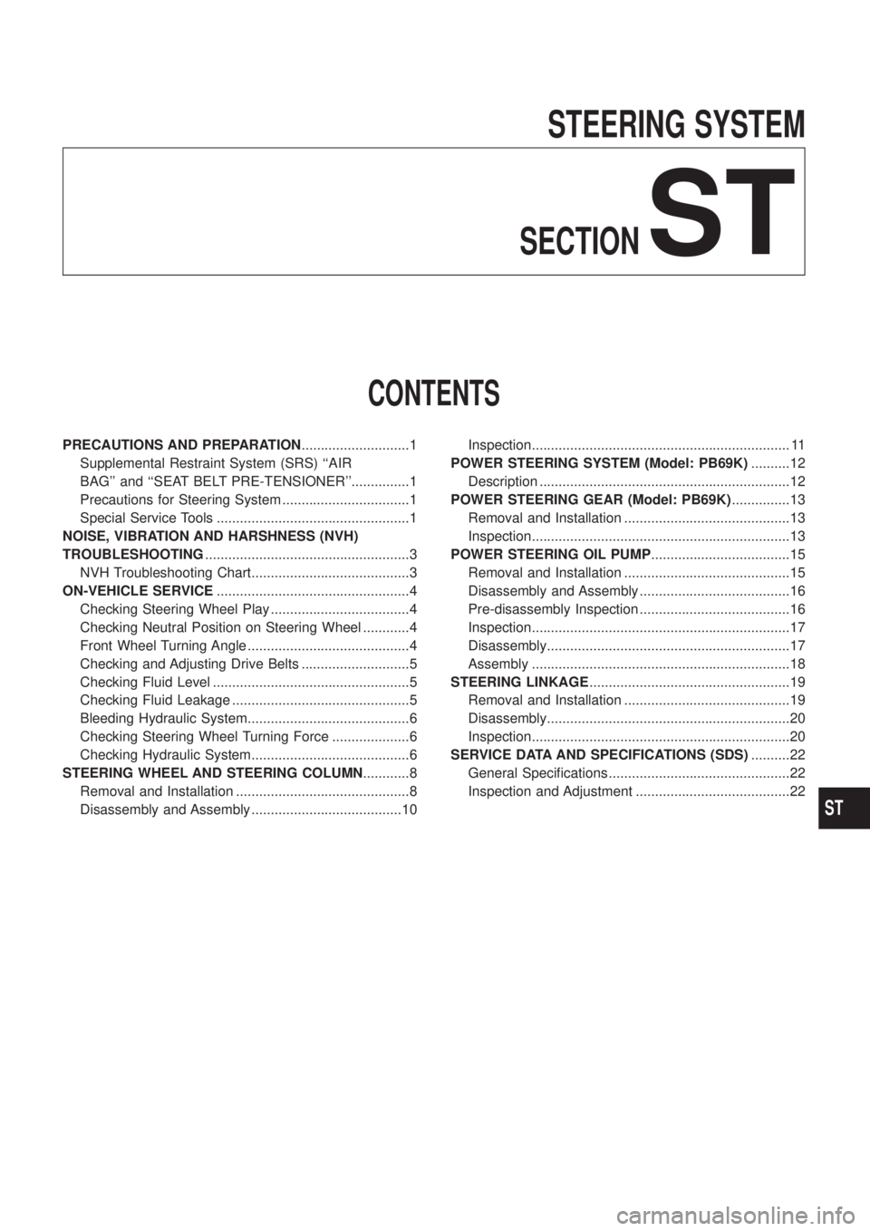
STEERING SYSTEM
SECTION
ST
CONTENTS
PRECAUTIONS AND PREPARATION............................1
Supplemental Restraint System (SRS) ``AIR
BAG'' and ``SEAT BELT PRE-TENSIONER''...............1
Precautions for Steering System .................................1
Special Service Tools ..................................................1
NOISE, VIBRATION AND HARSHNESS (NVH)
TROUBLESHOOTING.....................................................3
NVH Troubleshooting Chart.........................................3
ON-VEHICLE SERVICE..................................................4
Checking Steering Wheel Play ....................................4
Checking Neutral Position on Steering Wheel ............4
Front Wheel Turning Angle ..........................................4
Checking and Adjusting Drive Belts ............................5
Checking Fluid Level ...................................................5
Checking Fluid Leakage ..............................................5
Bleeding Hydraulic System..........................................6
Checking Steering Wheel Turning Force ....................6
Checking Hydraulic System.........................................6
STEERING WHEEL AND STEERING COLUMN............8
Removal and Installation .............................................8
Disassembly and Assembly .......................................10Inspection................................................................... 11
POWER STEERING SYSTEM (Model: PB69K)..........12
Description .................................................................12
POWER STEERING GEAR (Model: PB69K)...............13
Removal and Installation ...........................................13
Inspection...................................................................13
POWER STEERING OIL PUMP....................................15
Removal and Installation ...........................................15
Disassembly and Assembly .......................................16
Pre-disassembly Inspection .......................................16
Inspection...................................................................17
Disassembly...............................................................17
Assembly ...................................................................18
STEERING LINKAGE....................................................19
Removal and Installation ...........................................19
Disassembly...............................................................20
Inspection...................................................................20
SERVICE DATA AND SPECIFICATIONS (SDS)..........22
General Speci®cations ...............................................22
Inspection and Adjustment ........................................22
ST
Page 1191 of 1226
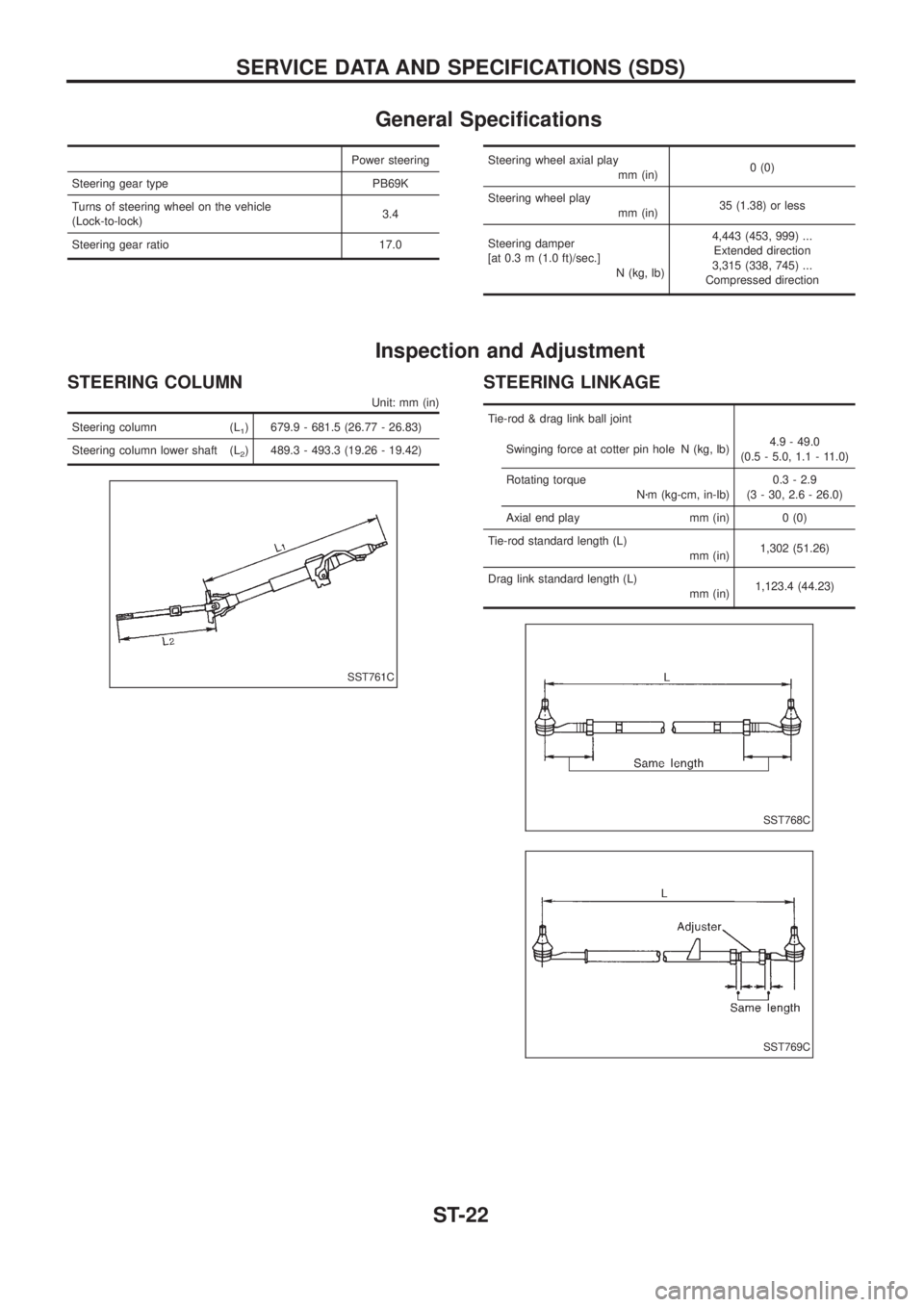
General Speci®cations
Power steering
Steering gear type PB69K
Turns of steering wheel on the vehicle
(Lock-to-lock)3.4
Steering gear ratio 17.0Steering wheel axial play
mm (in)0 (0)
Steering wheel play
mm (in)35 (1.38) or less
Steering damper
[at 0.3 m (1.0 ft)/sec.]
N (kg, lb)4,443 (453, 999) ...
Extended direction
3,315 (338, 745) ...
Compressed direction
Inspection and Adjustment
STEERING COLUMN
Unit: mm (in)
Steering column (L1) 679.9 - 681.5 (26.77 - 26.83)
Steering column lower shaft (L
2) 489.3 - 493.3 (19.26 - 19.42)
STEERING LINKAGE
Tie-rod & drag link ball joint
Swinging force at cotter pin hole N (kg, lb)4.9 - 49.0
(0.5 - 5.0, 1.1 - 11.0)
Rotating torque
Nzm (kg-cm, in-lb)0.3 - 2.9
(3 - 30, 2.6 - 26.0)
Axial end play mm (in) 0 (0)
Tie-rod standard length (L)
mm (in)1,302 (51.26)
Drag link standard length (L)
mm (in)1,123.4 (44.23)
SST761C
SST768C
SST769C
SERVICE DATA AND SPECIFICATIONS (SDS)
ST-22
Page 1192 of 1226
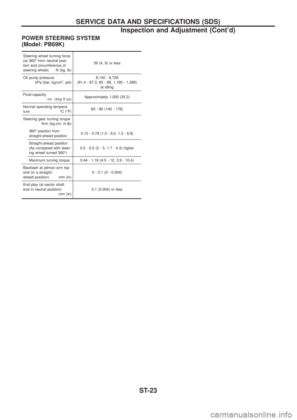
POWER STEERING SYSTEM
(Model: PB69K)
Steering wheel turning force
(at 360É from neutral posi-
tion and circumference of
steering wheel) N (kg, lb)39 (4, 9) or less
Oil pump pressure
kPa (bar, kg/cm
2, psi)8,140 - 8,728
(81.4 - 87.3, 83 - 89, 1,180 - 1,266)
at idling
Fluid capacity
m!(Imp ¯ oz)Approximately 1,000 (35.2)
Normal operating tempera-
ture ÉC (ÉF)60 - 80 (140 - 176)
Steering gear turning torque
Nzm (kg-cm, in-lb)
360É position from
straight-ahead position0.15 - 0.78 (1.5 - 8.0, 1.3 - 6.9)
Straight-ahead position
(As compared with steer-
ing wheel turned 360É)0.2 - 0.5 (2 - 5, 1.7 - 4.3) higher
Maximum turning torque 0.44 - 1.18 (4.5 - 12, 3.9 - 10.4)
Backlash at pitman arm top
end (in a straight-
ahead position) mm (in)0 - 0.1 (0 - 0.004)
End play (at sector shaft
end in neutral position)
mm (in)0.1 (0.004) or less
SERVICE DATA AND SPECIFICATIONS (SDS)
Inspection and Adjustment (Cont'd)
ST-23