Page 12 of 1226

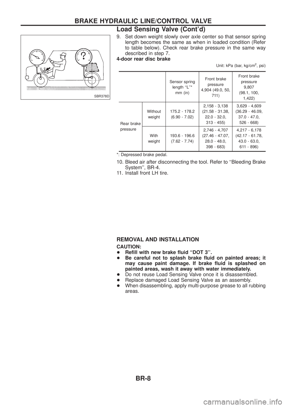
9. Set down weight slowly over axle center so that sensor springlength becomes the same as when in loaded condition (Refer
to table below). Check rear brake pressure in the same way
described in step 7.
4-door rear disc brake
Unit: kPa (bar, kg/cm2, psi)
Sensor spring
length ``L''* mm (in) Front brake
pressure
4,904 (49.0, 50, 711) Front brake
pressure 9,807
(98.1, 100, 1,422)
Rear brake
pressure Without
weight 175.2 - 178.2
(6.90 - 7.02) 2,158 - 3,138
(21.58 - 31.38, 22.0 - 32.0,313 - 455) 3,629 - 4,609
(36.29 - 46.09, 37.0 - 47.0,526 - 668)
With
weight 193.6 - 196.6
(7.62 - 7.74) 2,746 - 4,707
(27.46 - 47.07, 28.0 - 48.0,398 - 683) 4,217 - 6,178
(42.17 - 61.78, 43.0 - 63.0,611 - 896)
*: Depressed brake pedal.
10. Bleed air after disconnecting the tool. Refer to ``Bleeding Brake System'', BR-4.
11. Install front LH tire.
REMOVAL AND INSTALLATION
CAUTION:
+ Re®ll with new brake ¯uid ``DOT 3''.
+ Be careful not to splash brake ¯uid on painted areas; it
may cause paint damage. If brake ¯uid is splashed on
painted areas, wash it away with water immediately.
+ Do not reuse Load Sensing Valve once it is disassembled.
+ Replace damaged Load Sensing Valve as an assembly.
+ When disassembling, apply multi-purpose grease to all rubbing
areas.
SBR378D
BRAKE HYDRAULIC LINE/CONTROL VALVE
Load Sensing Valve (Cont'd)
BR-8
Page 39 of 1226

G SENSOR
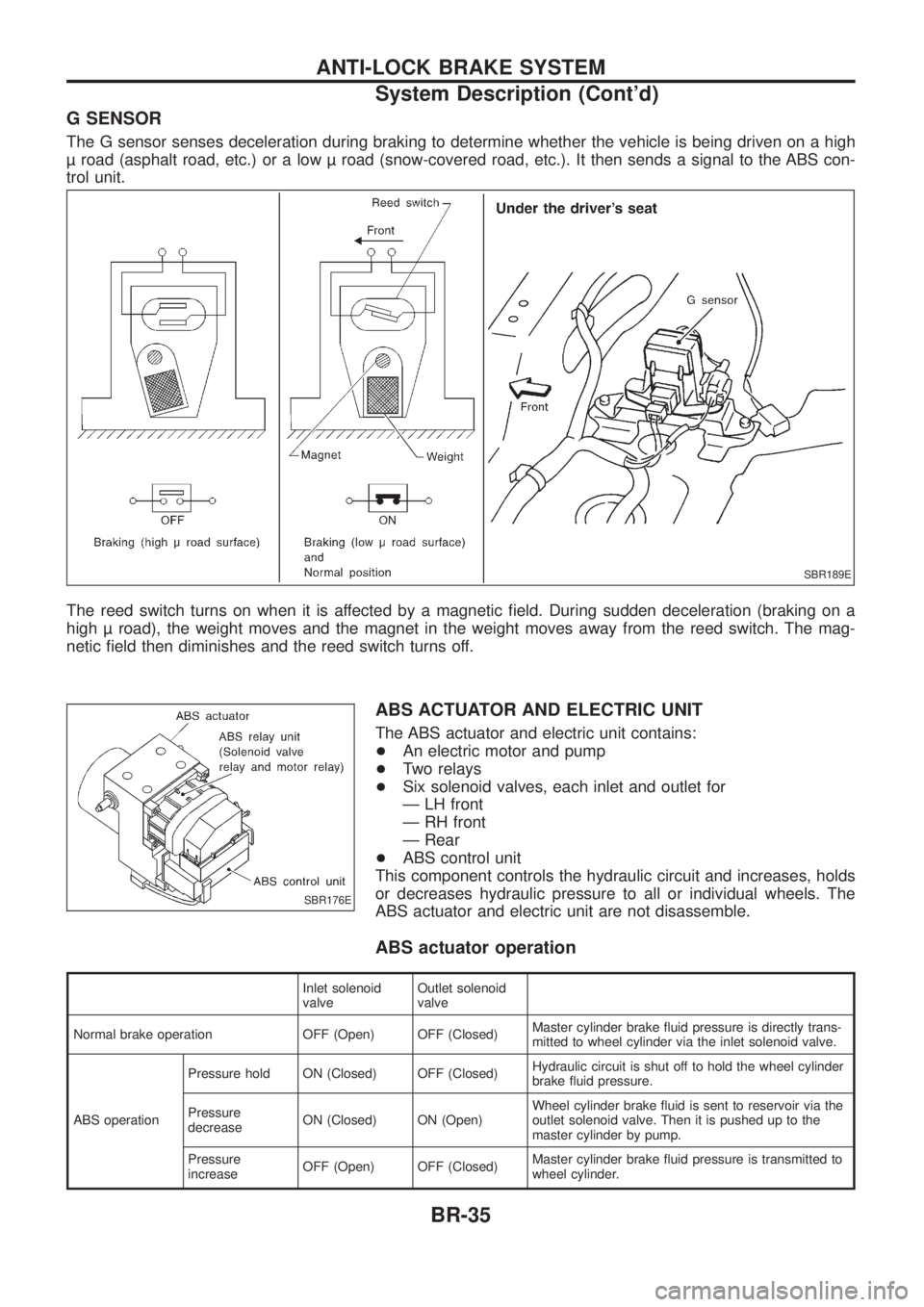
The G sensor senses deceleration during braking to determine whether the vehicle is being driven on a high
road (asphalt road, etc.) or a low road (snow-covered road, etc.). It then sends a signal to the ABS con-
trol unit.
The reed switch turns on when it is affected by a magnetic ®eld. During sudden deceleration (braking on a
high road), the weight moves and the magnet in the weight moves away from the reed switch. The mag-
netic ®eld then diminishes and the reed switch turns off.
ABS ACTUATOR AND ELECTRIC UNIT
The ABS actuator and electric unit contains:
+An electric motor and pump
+ Two relays
+ Six solenoid valves, each inlet and outlet for
Ð LH front
Ð RH front
Ð Rear
+ ABS control unit
This component controls the hydraulic circuit and increases, holds
or decreases hydraulic pressure to all or individual wheels. The
ABS actuator and electric unit are not disassemble.
ABS actuator operation
Inlet solenoid
valve Outlet solenoid
valve
Normal brake operation OFF (Open) OFF (Closed) Master cylinder brake ¯uid pressure is directly trans-
mitted to wheel cylinder via the inlet solenoid valve.
ABS operation Pressure hold ON (Closed) OFF (Closed)
Hydraulic circuit is shut off to hold the wheel cylinder
brake ¯uid pressure.
Pressure
decrease ON (Closed) ON (Open) Wheel cylinder brake ¯uid is sent to reservoir via the
outlet solenoid valve. Then it is pushed up to the
master cylinder by pump.
Pressure
increase OFF (Open) OFF (Closed) Master cylinder brake ¯uid pressure is transmitted to
wheel cylinder.
SBR189E
SBR176E
ANTI-LOCK BRAKE SYSTEM
System Description (Cont'd)
BR-35
Page 175 of 1226
4. Clean spray hole of nozzle body by using Tool.
To prevent spray hole from canting, always clean it by start-
ing with inner side and working towards outside.
5. Decarbonate nozzle needle tip by using Tool.
6. Check needle sinking.
(1) Pull needle about halfway out from body and then release it.
(2) Needle should sink into body very smoothly from just its own
weight.
(3) Repeat this test and rotate needle slightly each time.
If needle fails to sink smoothly from any position, replace both
needle and body as a unit.
Assembly (No.2-4nozzles)
Assemble in the reverse order of disassembly, observing the fol-
lowing.
If nozzle body is not installed properly, Tool cannot be
removed and nozzle body may be damaged.
Holder to nozzle nut:
: 78-98Nzm (8.0 - 10.0 kg-m, 58 - 72 ft-lb)
SEF833
SEF834
SEF835
SEF671A
INJECTION NOZZLE
Cleaning (No.2-4nozzles) (Cont'd)
EC-24
Page 408 of 1226

Bulb Replacement
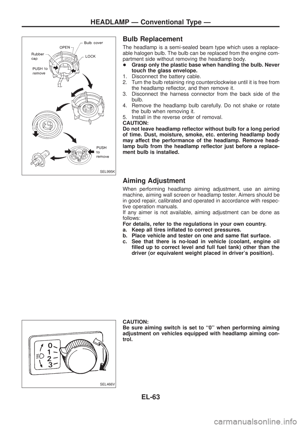
The headlamp is a semi-sealed beam type which uses a replace-
able halogen bulb. The bulb can be replaced from the engine com-
partment side without removing the headlamp body.
+Grasp only the plastic base when handling the bulb. Never
touch the glass envelope.
1. Disconnect the battery cable.
2. Turn the bulb retaining ring counterclockwise until it is free from
the headlamp re¯ector, and then remove it.
3. Disconnect the harness connector from the back side of the
bulb.
4. Remove the headlamp bulb carefully. Do not shake or rotate
the bulb when removing it.
5. Install in the reverse order of removal.
CAUTION:
Do not leave headlamp re¯ector without bulb for a long period
of time. Dust, moisture, smoke, etc. entering headlamp body
may affect the performance of the headlamp. Remove head-
lamp bulb from the headlamp re¯ector just before a replace-
ment bulb is installed.
Aiming Adjustment
When performing headlamp aiming adjustment, use an aiming
machine, aiming wall screen or headlamp tester. Aimers should be
in good repair, calibrated and operated in accordance with respec-
tive operation manuals.
If any aimer is not available, aiming adjustment can be done as
follows:
For details, refer to the regulations in your own country.
a. Keep all tires in¯ated to correct pressures.
b. Place vehicle and tester on one and same ¯at surface.
c. See that there is no-load in vehicle (coolant, engine oil
®lled up to correct level and full fuel tank) other than the
driver (or equivalent weight placed in driver's position).
CAUTION:
Be sure aiming switch is set to ``0'' when performing aiming
adjustment on vehicles equipped with headlamp aiming con-
trol.
SEL995K
SEL466V
HEADLAMP Ð Conventional Type Ð
EL-63
Page 775 of 1226

General Precautions
+Do not operate the engine for an extended period of time with-
out proper exhaust ventilation.
Keep the work area well ventilated and free of any in¯ammable
materials. Special care should be taken when handling any
in¯ammable or poisonous materials, such as gasoline, refriger-
ant gas, etc. When working in a pit or other enclosed area, be
sure to properly ventilate the area before working with hazard-
ous materials.
Do not smoke while working on the vehicle.
+Before jacking up the vehicle, apply wheel chocks or other tire
blocks to the wheels to prevent the vehicle from moving. After
jacking up the vehicle, support the vehicle weight with safety
stands at the points designated for proper lifting before work-
ing on the vehicle.
These operations should be done on a level surface.
+When removing a heavy component such as the engine or
transaxle/transmission, be careful not to lose your balance and
drop it. Also, do not allow it to strike adjacent parts, especially
the brake tubes and master cylinder.
+Before starting repairs which do not require battery power:
Turn off ignition switch.
Disconnect the negative battery terminal.
+To prevent serious burns:
Avoid contact with hot metal parts.
Do not remove the radiator cap when the engine is hot.
+Before servicing the vehicle:
Protect fenders, upholstery and carpeting with appropriate cov-
ers.
Take caution that keys, buckles or buttons do not scratch paint.
SGI285
SGI231
SEF289H
SGI233
SGI234
PRECAUTIONS
GI-2
Page 787 of 1226
DETECTABLE LINES AND NON-DETECTABLE LINES
In some wiring diagrams, two kinds of lines, representing wires,
with different weight are used.
+A line with regular weight (wider line) represents a ``detectable
line for DTC (Diagnostic Trouble Code)''. A ``detectable line for
DTC'' is a circuit in which ECM (Engine Control Module) can
detect its malfunctions with the on board diagnostic system.
+A line with less weight (thinner line) represents a ``non-detect-
able line for DTC''. A ``non-detectable line for DTC'' is a circuit
in which ECM cannot detect its malfunctions with the on board
diagnostic system.
SGI862-A
HOW TO READ WIRING DIAGRAMS
Description (Cont'd)
GI-14
Page 829 of 1226
Tool name Description Note
Service hoses
+High side hose
+Low side hose
+Utility hose
NT201
Hose color:
+Low hose: Blue with black stripe
+High hose: Red with black stripe
+Utility hose: Yellow with black stripe or
green with black stripe
Hose ®tting to gauge:
+1/2²-16 ACME
Service couplers
+High side coupler
+Low side coupler
NT202
Hose ®tting to service hose:
+M14 x 1.5 ®tting is optional or
permanently attached.
Refrigerant weight scale
NT200
For measuring of refrigerant
Fitting size: Thread size
+1/2²-16 ACME
Vacuum pump
(Including the isolator
valve)
NT203
Capacity:
+Air displacement: 4 CFM
+Micron rating: 20 microns
+Oil capacity: 482 g (17 oz)
Fitting size: Thread size
+1/2²-16 ACME
PRECAUTIONS AND PREPARATIONMANUAL AND AUTO
HFC-134a (R-134a) Service Tools and
Equipment (Cont'd)
HA-8
Page 831 of 1226

SERVICE COUPLERS
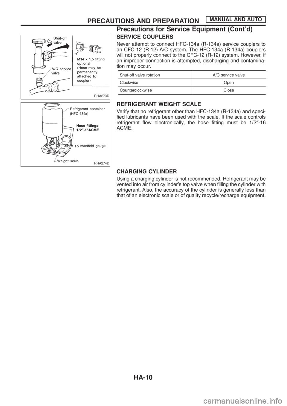
Never attempt to connect HFC-134a (R-134a) service couplers to
an CFC-12 (R-12) A/C system. The HFC-134a (R-134a) couplers
will not properly connect to the CFC-12 (R-12) system. However, if
an improper connection is attempted, discharging and contamina-
tion may occur.
Shut-off valve rotation A/C service valve
Clockwise Open
Counterclockwise Close
REFRIGERANT WEIGHT SCALE
Verify that no refrigerant other than HFC-134a (R-134a) and speci-
®ed lubricants have been used with the scale. If the scale controls
refrigerant ¯ow electronically, the hose ®tting must be 1/2²-16
ACME.
CHARGING CYLINDER
Using a charging cylinder is not recommended. Refrigerant may be
vented into air from cylinder's top valve when ®lling the cylinder with
refrigerant. Also, the accuracy of the cylinder is generally less than
that of an electronic scale or of quality recycle/recharge equipment.
RHA273D
RHA274D
PRECAUTIONS AND PREPARATIONMANUAL AND AUTO
Precautions for Service Equipment (Cont'd)
HA-10