2006 NISSAN PATROL remove seats
[x] Cancel search: remove seatsPage 92 of 1226
Side and Floor Trim
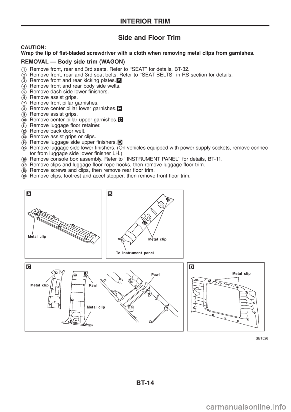
CAUTION:
Wrap the tip of ¯at-bladed screwdriver with a cloth when removing metal clips from garnishes.
REMOVAL Ð Body side trim (WAGON)
V1Remove front, rear and 3rd seats. Refer to ``SEAT'' for details, BT-32.
V2Remove front, rear and 3rd seat belts. Refer to ``SEAT BELTS'' in RS section for details.
V3Remove front and rear kicking plates.
V4Remove front and rear body side welts.
V5Remove dash side lower ®nishers.
V6Remove assist grips.
V7Remove front pillar garnishes.
V8Remove center pillar lower garnishes.
V9Remove assist grips.
V10Remove center pillar upper garnishes.
V11Remove luggage ¯oor retainer.
V12Remove back door welt.
V13Remove assist grips or clips.
V14Remove luggage side upper ®nishers.
V15Remove luggage side lower ®nishers. (On vehicles equipped with power supply sockets, remove connec-
tor from luggage side lower ®nisher LH.)
V16Remove console box assembly. Refer to ``INSTRUMENT PANEL'' for details, BT-11.
V17Remove clips and luggage ¯oor rope hooks, then remove luggage ¯oor trim.
V18Remove screws and clips, then remove rear ¯oor trim.
V19Remove clips, footrest and accel stopper, then remove front ¯oor trim.
SBT526
INTERIOR TRIM
BT-14
Page 94 of 1226
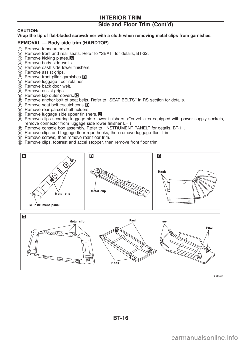
CAUTION:
Wrap the tip of ¯at-bladed screwdriver with a cloth when removing metal clips from garnishes.
REMOVAL Ð Body side trim (HARDTOP)
V1Remove tonneau cover.
V2Remove front and rear seats. Refer to ``SEAT'' for details, BT-32.
V3Remove kicking plates.
V4Remove body side welts.
V5Remove dash side lower ®nishers.
V6Remove assist grips.
V7Remove front pillar garnishes.
V8Remove luggage ¯oor retainer.
V9Remove back door welt.
V10Remove assist grips.
V11Remove lap outer covers.
V12Remove anchor bolt of seat belts. Refer to ``SEAT BELTS'' in RS section for details.
V13Remove seat belt escutcheons.
V14Remove rear parcel shelf holders.
V15Remove luggage side upper ®nishers.
V16Remove clips securing luggage side lower ®nishers. (On vehicles equipped with power supply sockets,
remove connector from luggage side lower ®nisher LH.)
V17Remove console box assembly. Refer to ``INSTRUMENT PANEL'' for details, BT-11.
V18Remove clips and luggage ¯oor rope hooks, then remove luggage ¯oor trim.
V19Remove screws, then remove rear ¯oor trim.
V20Remove clips, footrest and accel stopper, then remove front ¯oor trim.
SBT528
INTERIOR TRIM
Side and Floor Trim (Cont'd)
BT-16
Page 98 of 1226

Roof Trim
REMOVAL Ð Headlining (WAGON)
V1Remove front, rear and 3rd seats. Refer to ``SEAT'' for details, BT-32.
V2Remove front, rear and 3rd seat belts. Refer to ``SEAT BELTS'' in RS section for details.
V3Remove body side trim. Refer to ``Side and Floor Trim'' for details, BT-14.
V4Remove roof console assembly, then disconnect connectors.
V5Remove inside mirror assembly.
V6Remove sun visors.
V7Remove interior lamp assembly.
V8Remove luggage room lamp assembly.
V9Remove assist grips.
V10Remove clips securing headlining.
V11Remove rear headlining from vehicle through either back door.
V12Remove front headlining from vehicle through either back door.
SBT531
INTERIOR TRIM
BT-20
Page 100 of 1226
REMOVAL Ð Headlining (HARDTOP)
V1Remove front and rear seats. Refer to ``SEAT'' for details, BT-32.
V2Remove front and rear seat belts. Refer to ``SEAT BELTS'' in RS section for details.
V3Remove body side trim. Refer to ``Side and Floor Trim'' for details, BT-14.
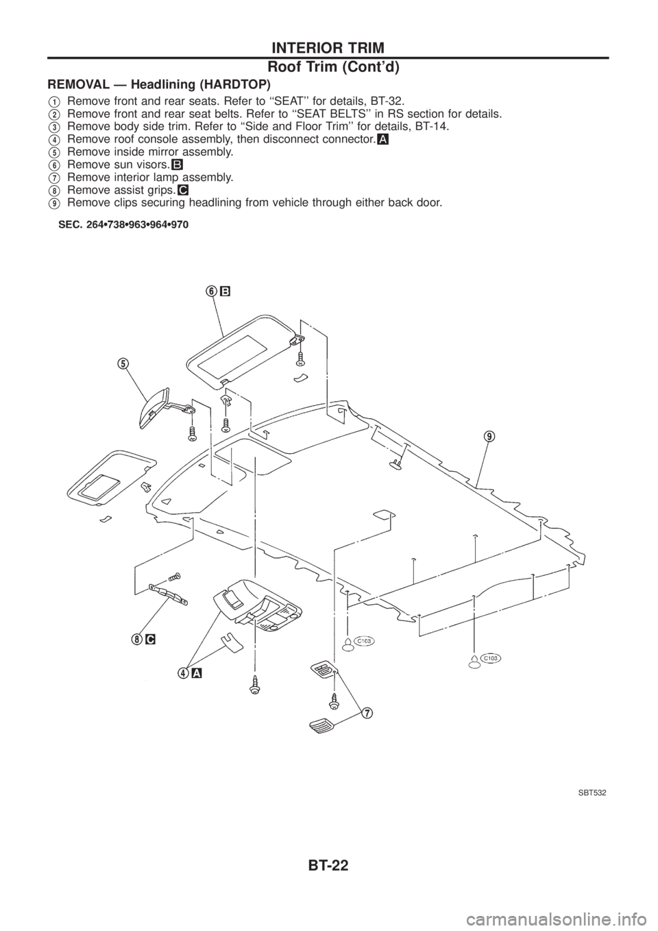
V4Remove roof console assembly, then disconnect connector.
V5Remove inside mirror assembly.
V6Remove sun visors.
V7Remove interior lamp assembly.
V8Remove assist grips.
V9Remove clips securing headlining from vehicle through either back door.
SBT532
INTERIOR TRIM
Roof Trim (Cont'd)
BT-22
Page 689 of 1226
VALVE OIL SEAL
1. Remove timing belts.
2. Remove camshaft sprocket and back covers.
3. Remove camshaft brackets by loosening bracket nuts from
center to outside in two or three stages.
4. Remove camshaft oil seals and camshaft.
5. Remove valve lifters and mark order No. on each lifter.
6. Replace valve oil seal according to the following procedure.
When replacing valve oil seal, set the corresponding piston at
TDC. Failure to do so causes the valve to drop into the cylin-
der.
1) Set No. 1 cylinder at TDC.
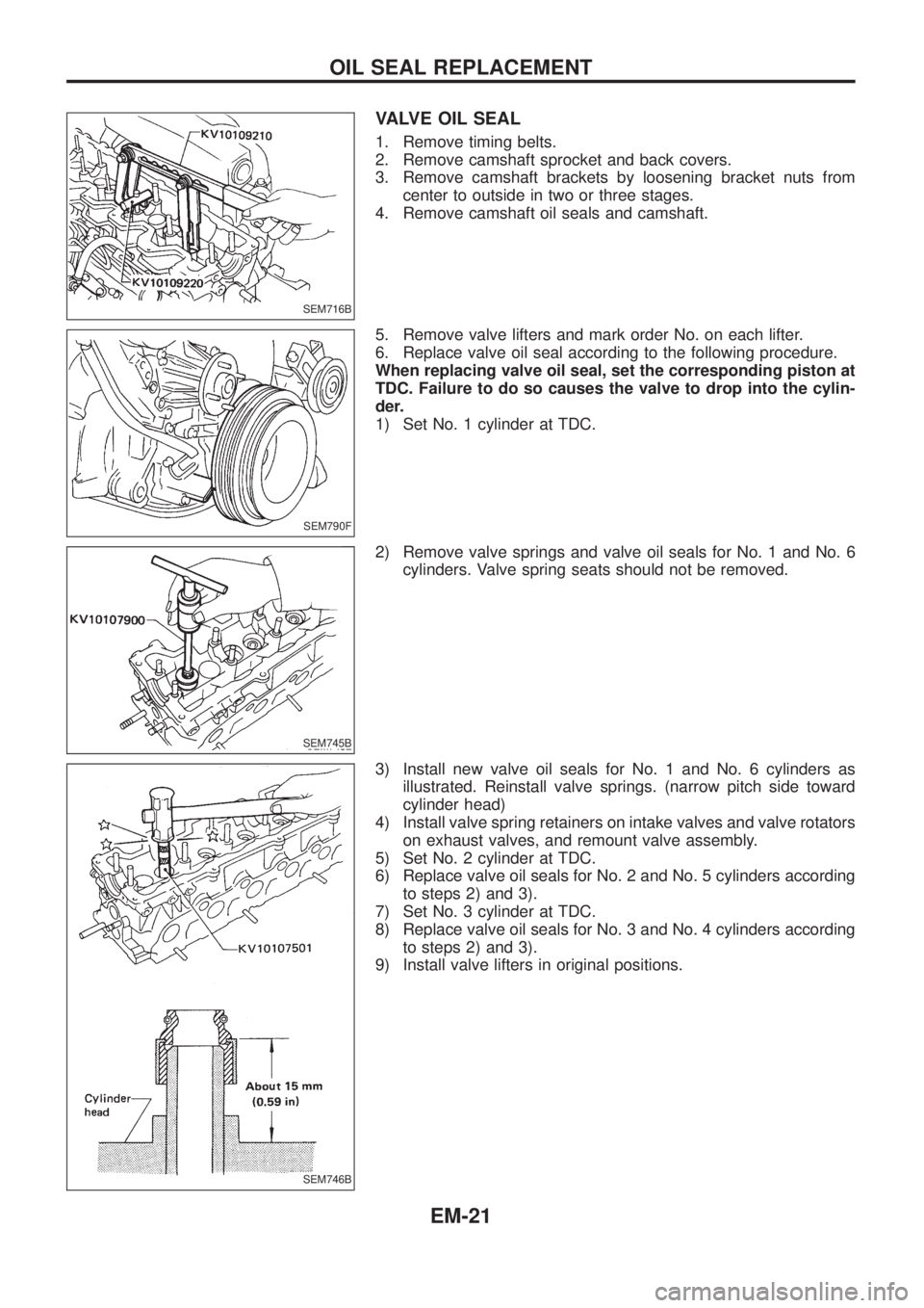
2) Remove valve springs and valve oil seals for No. 1 and No. 6
cylinders. Valve spring seats should not be removed.
3) Install new valve oil seals for No. 1 and No. 6 cylinders as
illustrated. Reinstall valve springs. (narrow pitch side toward
cylinder head)
4) Install valve spring retainers on intake valves and valve rotators
on exhaust valves, and remount valve assembly.
5) Set No. 2 cylinder at TDC.
6) Replace valve oil seals for No. 2 and No. 5 cylinders according
to steps 2) and 3).
7) Set No. 3 cylinder at TDC.
8) Replace valve oil seals for No. 3 and No. 4 cylinders according
to steps 2) and 3).
9) Install valve lifters in original positions.
SEM716B
SEM790F
SEM745B
SEM746B
OIL SEAL REPLACEMENT
EM-21
Page 701 of 1226
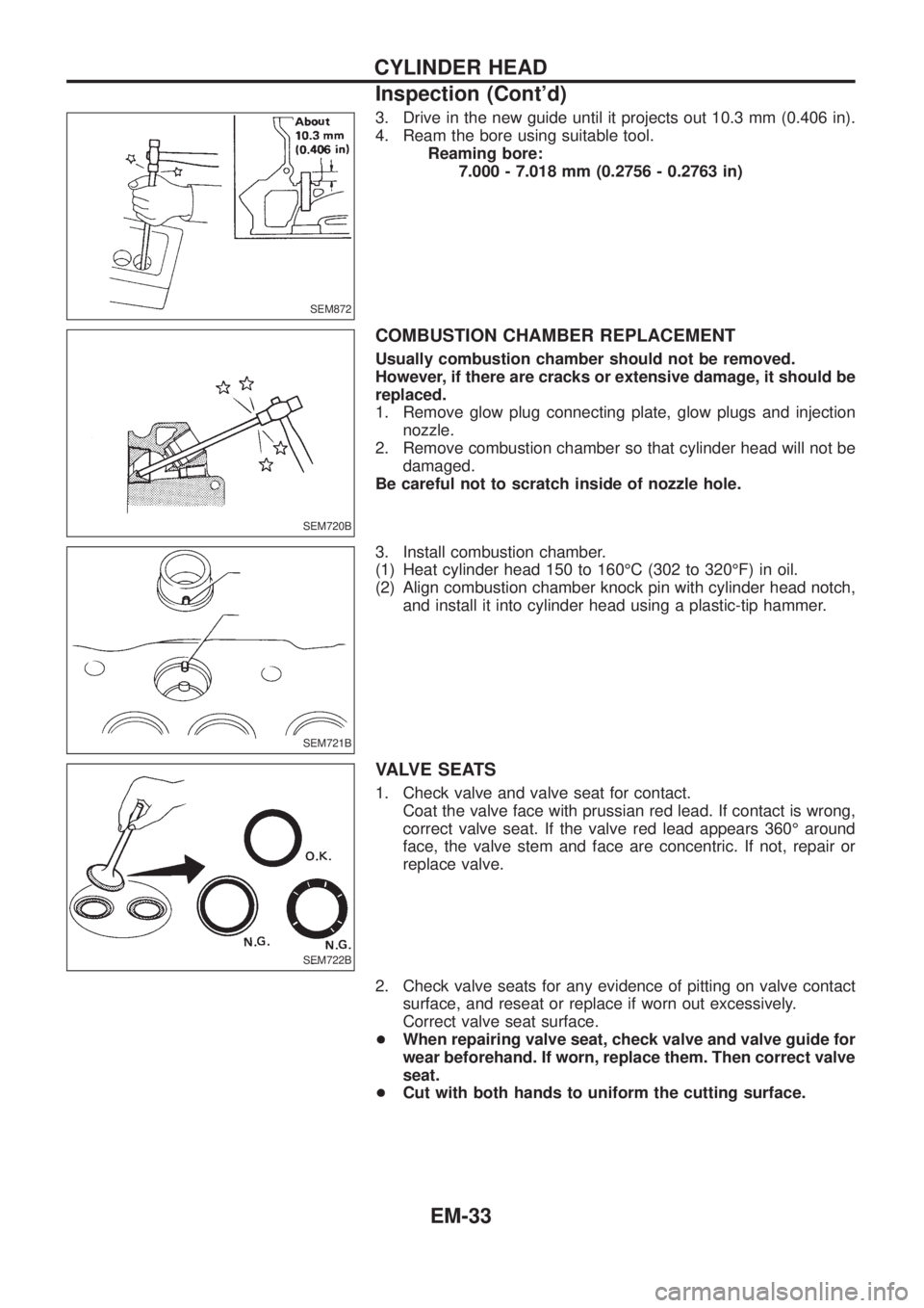
3. Drive in the new guide until it projects out 10.3 mm (0.406 in).
4. Ream the bore using suitable tool.
Reaming bore:
7.000 - 7.018 mm (0.2756 - 0.2763 in)
COMBUSTION CHAMBER REPLACEMENT
Usually combustion chamber should not be removed.
However, if there are cracks or extensive damage, it should be
replaced.
1. Remove glow plug connecting plate, glow plugs and injection
nozzle.
2. Remove combustion chamber so that cylinder head will not be
damaged.
Be careful not to scratch inside of nozzle hole.
3. Install combustion chamber.
(1) Heat cylinder head 150 to 160ÉC (302 to 320ÉF) in oil.
(2) Align combustion chamber knock pin with cylinder head notch,
and install it into cylinder head using a plastic-tip hammer.
VALVE SEATS
1. Check valve and valve seat for contact.
Coat the valve face with prussian red lead. If contact is wrong,
correct valve seat. If the valve red lead appears 360É around
face, the valve stem and face are concentric. If not, repair or
replace valve.
2. Check valve seats for any evidence of pitting on valve contact
surface, and reseat or replace if worn out excessively.
Correct valve seat surface.
+When repairing valve seat, check valve and valve guide for
wear beforehand. If worn, replace them. Then correct valve
seat.
+Cut with both hands to uniform the cutting surface.
SEM872
SEM720B
SEM721B
SEM722B
CYLINDER HEAD
Inspection (Cont'd)
EM-33
Page 702 of 1226
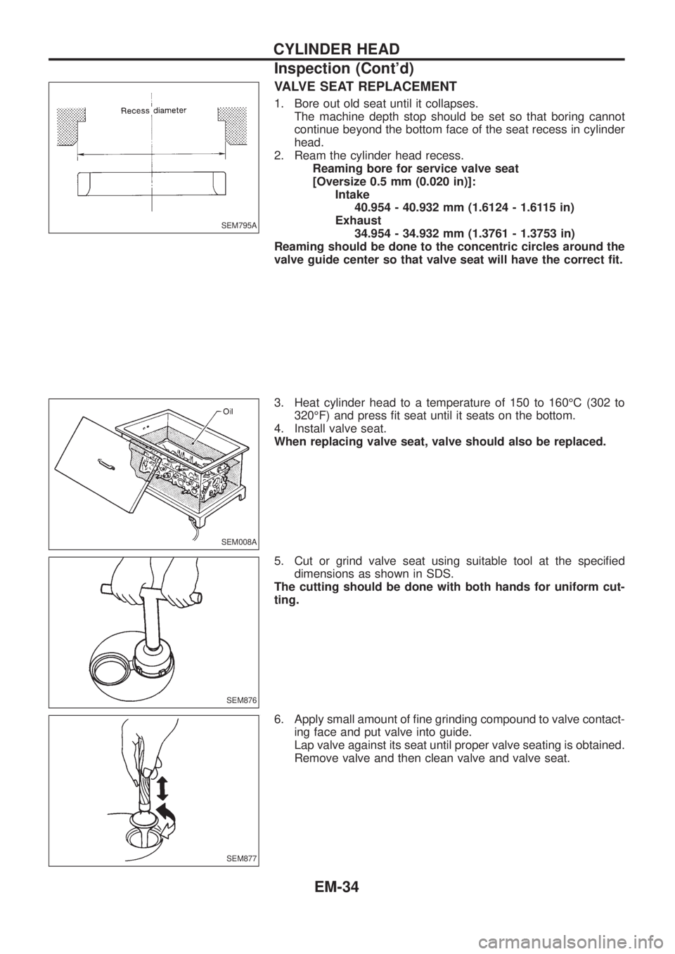
VALVE SEAT REPLACEMENT
1. Bore out old seat until it collapses.
The machine depth stop should be set so that boring cannot
continue beyond the bottom face of the seat recess in cylinder
head.
2. Ream the cylinder head recess.
Reaming bore for service valve seat
[Oversize 0.5 mm (0.020 in)]:
Intake
40.954 - 40.932 mm (1.6124 - 1.6115 in)
Exhaust
34.954 - 34.932 mm (1.3761 - 1.3753 in)
Reaming should be done to the concentric circles around the
valve guide center so that valve seat will have the correct ®t.
3. Heat cylinder head to a temperature of 150 to 160ÉC (302 to
320ÉF) and press ®t seat until it seats on the bottom.
4. Install valve seat.
When replacing valve seat, valve should also be replaced.
5. Cut or grind valve seat using suitable tool at the speci®ed
dimensions as shown in SDS.
The cutting should be done with both hands for uniform cut-
ting.
6. Apply small amount of ®ne grinding compound to valve contact-
ing face and put valve into guide.
Lap valve against its seat until proper valve seating is obtained.
Remove valve and then clean valve and valve seat.
SEM795A
SEM008A
SEM876
SEM877
CYLINDER HEAD
Inspection (Cont'd)
EM-34
Page 979 of 1226
Shown below are Pre-delivery Inspection Items required for the new vehicle. It is recommended that
necessary items other than those listed here be added, paying due regard to the conditions in each
country.
Perform applicable items on each model. Consult text of this section for speci®cations.
UNDER HOOD Ð engine off
hRadiator coolant level and coolant hose connec-
tions for leaks
hBattery ¯uid level, speci®c gravity and condi-
tions of battery terminals
hDrive belts tension
hFuel ®lter for water or dusts, and fuel lines and
connections for leaks
hEngine oil level and oil leaks
hClutch and brake reservoir ¯uid level and ¯uid
lines for leaks
hWindshield and rear window washer and head-
lamp cleaner reservoir ¯uid level
hPower steering reservoir ¯uid level and hose
connections for leaks
ON INSIDE AND OUTSIDE
hXRemove front spring/strut spacer (If applicable)
hOperation of all instruments, gauges, lights and
accessories
hOperation of horn(s), wiper and washer
hSteering lock for operation
hCheck air conditioner for gas leaks
hFront and rear seats, and seat belts for opera-
tion
hAll moldings, trims and ®ttings for ®t and align-
ment
hAll windows for operation and alignment
hHood, trunk lid, door panels for ®t and alignment
hLatches, keys and locks for operation
hWeatherstrips for adhesion and ®t
hHeadlamp aiming
hTighten wheel nuts (Inc. inner nuts if applicable)
hTire pressure (Inc. spare tire)
hCheck front wheels for toe-in
hInstall clock/voltmeter/room lamp fuse (If appli-
cable)
h
XInstall deodorizing ®lter to air puri®er (If appli-
cable)
h
XRemove wiper blade protectors (If applicable)
UNDER BODY
hManual transmission/transaxle gear oil, transfer
¯uid and differential gear oil level
hBrake and fuel lines and oil/¯uid reservoirs for
leaks
hTighten bolts and nuts of steering linkage and
gear box, suspension, propeller shafts and drive
shafts
h
XTighten rear body bolts and nuts (Models with
wooden bed only)
ROAD TEST
hClutch operation
hParking brake operation
hService brake operation
hAutomatic transmission/transaxle shift timing
and kickdown
hSteering control and returnability
hEngine performance
hSqueaks and rattles
ENGINE OPERATING AND HOT
hAdjust idle mixture and speed (and ignition tim-
ing*1)
hAutomatic transmission/transaxle ¯uid level
hEngine idling and stop knob operation (Diesel
only)
FINAL INSPECTION
hInstall necessary parts (outside mirror, wheel
covers, seat belts, mat, carpet or mud ¯aps)
hInspect for interior and exterior metal and paint
damage
hCheck for spare tire, jack, tools (wheel chock),
and literature
hWash, clean interior and exterior
*1: Not required on models with a direct ignition system
h
X: Not applicable to this model.
PRE-DELIVERY INSPECTION ITEMS
MA-2