Page 14 of 1226
Removal and Installation
Inspection
Check brake pedal for following items.
+Brake pedal bend
+ Clevis pin deformation
+ Crack of any welded portion
+ Crack or deformation of clevis pin stopper
Adjustment
Check brake pedal free height from dash lower panel.
H: Free height Refer to SDS (BR-72).
D: Depressed height Refer to SDS (BR-72).
Under force of 490 N (50 kg, 110 lb)
with engine running
C
1,C2: Clearance between pedal stopper and threaded end of stop lamp switch and ASCD
switch 0.3 - 1.0 mm (0.012 - 0.039 in)
A: Pedal free play 1-3mm(0.04 - 0.12 in)
If necessary, adjust brake pedal free height.
SBR163E
SBR463CB
BRAKE PEDAL AND BRACKET
BR-10
Page 15 of 1226
1. Loosen lock nut and adjust pedal free height by turning brakebooster input rod. Then tighten lock nut.
Make sure that tip of input rod stays inside.
2. Adjust clearance ``C
1'' and ``C2'' with stop lamp switch and
ASCD switch respectively. Then tighten lock nuts.
3. Check pedal free play.
Make sure that stop lamp is off when pedal is released.
4. Check brake pedal's depressed height while engine is running. If depressed height is below speci®ed value, check brake sys-
tem for leaks, accumulation of air or any damage to compo-
nents (master cylinder, wheel cylinder, etc.). Then make nec-
essary repairs.
SBR824B
BRAKE PEDAL AND BRACKET
Adjustment (Cont'd)
BR-11
Page 20 of 1226
1. Before ®tting booster, temporarily adjust clevis to dimensionshown.
2. Fit booster, then secure mounting nuts (brake pedal bracket to brake booster) lightly.
3. Connect brake pedal and booster input rod with clevis pin.
4. Secure mounting nuts. Speci®cation: 13 - 16 N zm (1.3 - 1.6 kg-m ,9-12ft-lb)
5. Install master cylinder. Refer to ``Installation'' in ``MASTER CYLINDER'', BR-14.
6. Adjust brake pedal height and free play. Refer to ``Adjustment'' in ``BRAKE PEDAL AND BRACKET'',
BR-10.
7. Secure lock nut for clevis.
:16-22N zm (1.6 - 2.2 kg-m, 12 - 16 ft-lb)
8. Bleed air. Refer to ``Bleeding Brake System'', BR-4.
BRAKE BOOSTER
Brake Booster (Cont'd)
BR-16
Page 77 of 1226

Inspection and Adjustment
DISC BRAKE
Unit: mm (in)
Brake model CL36VE CL18VF
Pad wear limit
Minimum thickness 2.0 (0.079)
Rotor repair limit
Minimum thickness 30.0 (1.181) 16.0 (0.630)
PARKING CENTER BRAKE
Unit: mm (in)
Brake model DS20HB
Lining wear limit
Minimum thickness 1.5 (0.059)
Drum repair limit
Maximum inner diameter 204.5 (8.05)
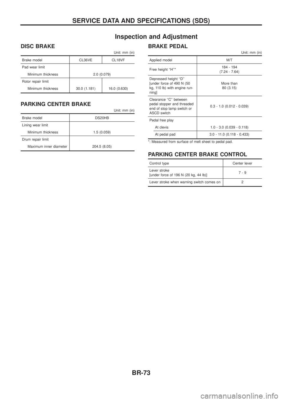
BRAKE PEDAL
Unit: mm (in)
Applied model M/T
Free height ``H''*184 - 194
(7.24 - 7.64)
Depressed height ``D''
[under force of 490 N (50
kg, 110 lb) with engine run-
ning]More than
80 (3.15)
Clearance ``C'' between
pedal stopper and threaded
end of stop lamp switch or
ASCD switch0.3 - 1.0 (0.012 - 0.039)
Pedal free play
At clevis 1.0 - 3.0 (0.039 - 0.118)
At pedal pad 3.0 - 11.0 (0.118 - 0.433)
*: Measured from surface of melt sheet to pedal pad.
PARKING CENTER BRAKE CONTROL
Control type Center lever
Lever stroke
[under force of 196 N (20 kg, 44 lb)]7-9
Lever stroke when warning switch comes on 2
SERVICE DATA AND SPECIFICATIONS (SDS)
BR-73
Page 138 of 1226
Adjusting Clutch Pedal
1. Adjust pedal height with pedal stopper.
Pedal height ``H*'':
195 - 205 mm (7.68 - 8.07 in)
*: Measured from surface of dash reinforcement panel to
pedal pad
2. Adjust pedal free play with master cylinder push rod or clutch
booster input rod. Then tighten lock nut.
Pedal free play ``A'':
1.0 - 3.0 mm (0.039 - 0.118 in)
Pedal free play means the following total measured at position
of pedal pad:
+Play due to clevis pin and clevis pin hole in clutch pedal.
+Play due to piston and push rod.
+Push or step on clutch pedal until resistance is felt, and check
the distance the pedal moves.
SCL788
SCL702
INSPECTION AND ADJUSTMENT
CL-5
Page 147 of 1226

Clutch Cover and Flywheel
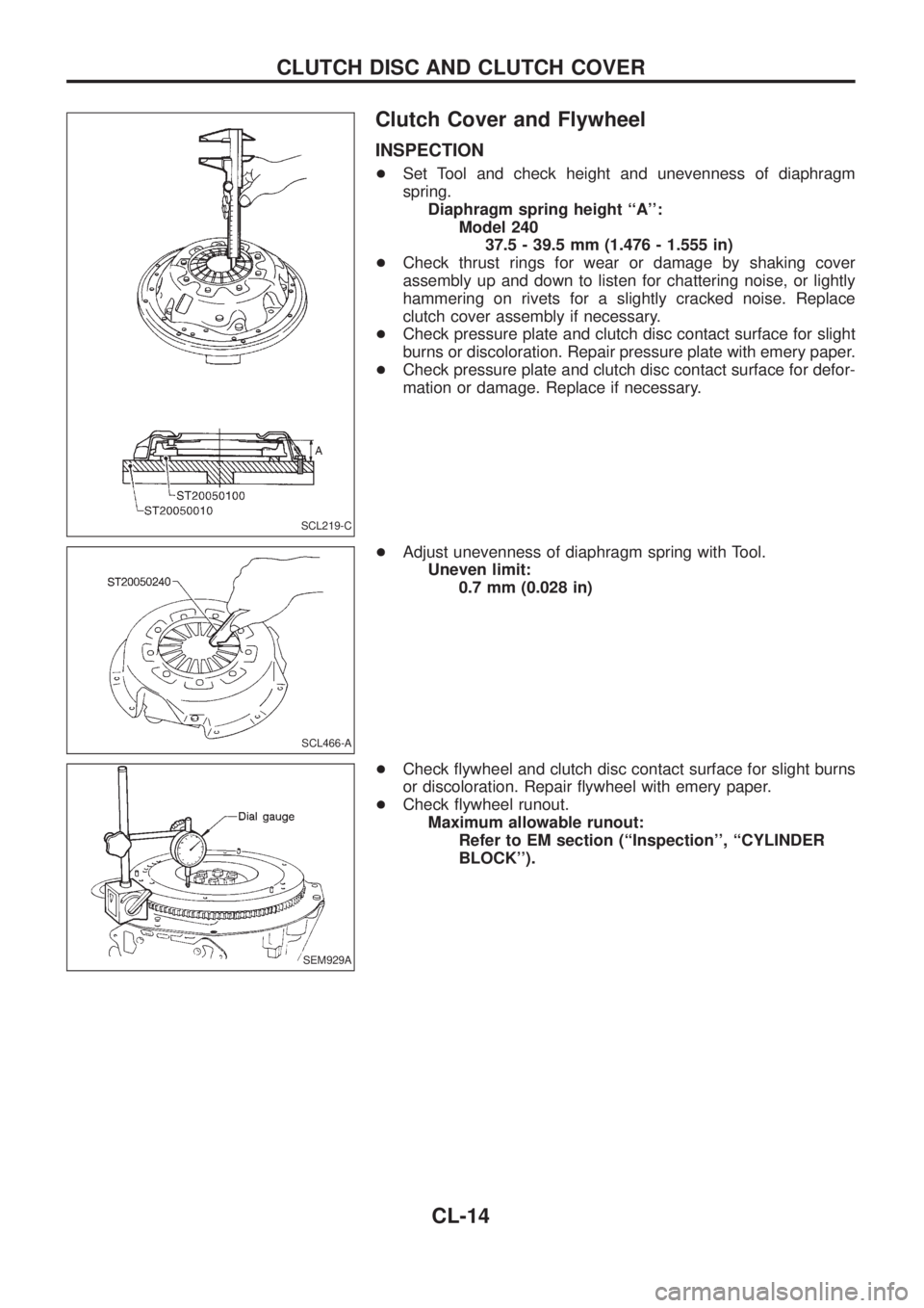
INSPECTION
+Set Tool and check height and unevenness of diaphragm
spring.
Diaphragm spring height ``A'':
Model 240
37.5 - 39.5 mm (1.476 - 1.555 in)
+Check thrust rings for wear or damage by shaking cover
assembly up and down to listen for chattering noise, or lightly
hammering on rivets for a slightly cracked noise. Replace
clutch cover assembly if necessary.
+Check pressure plate and clutch disc contact surface for slight
burns or discoloration. Repair pressure plate with emery paper.
+Check pressure plate and clutch disc contact surface for defor-
mation or damage. Replace if necessary.
+Adjust unevenness of diaphragm spring with Tool.
Uneven limit:
0.7 mm (0.028 in)
+Check ¯ywheel and clutch disc contact surface for slight burns
or discoloration. Repair ¯ywheel with emery paper.
+Check ¯ywheel runout.
Maximum allowable runout:
Refer to EM section (``Inspection'', ``CYLINDER
BLOCK'').
SCL219-C
SCL466-A
SEM929A
CLUTCH DISC AND CLUTCH COVER
CL-14
Page 149 of 1226

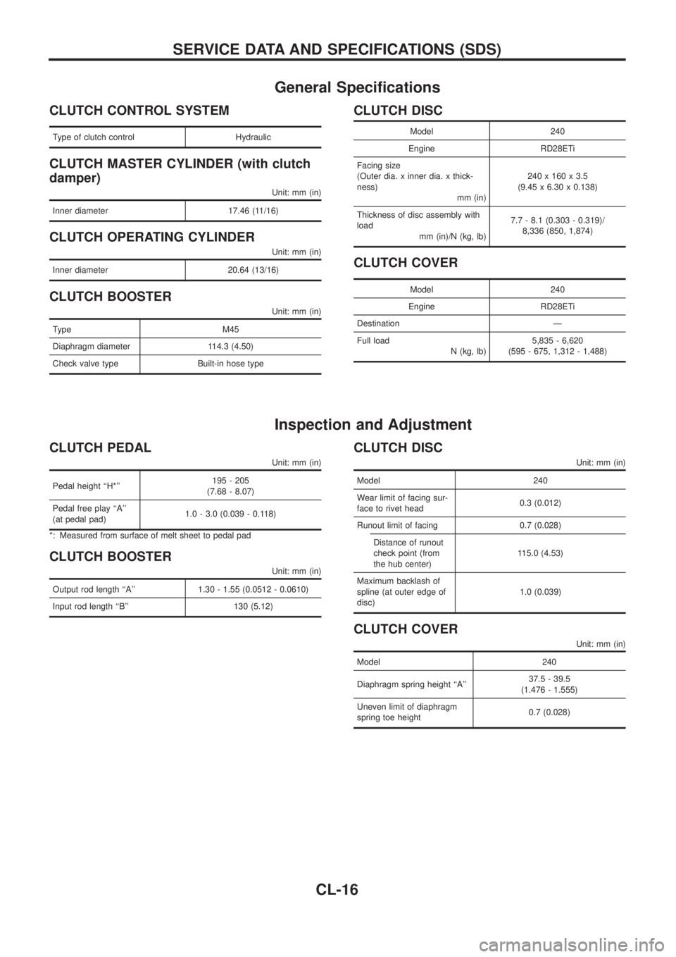
General Speci®cations
CLUTCH CONTROL SYSTEM
Type of clutch control Hydraulic
CLUTCH MASTER CYLINDER (with clutch
damper)
Unit: mm (in)
Inner diameter 17.46 (11/16)
CLUTCH OPERATING CYLINDER
Unit: mm (in)
Inner diameter 20.64 (13/16)
CLUTCH BOOSTER
Unit: mm (in)
Type M45
Diaphragm diameter 114.3 (4.50)
Check valve type Built-in hose type
CLUTCH DISC
Model 240
Engine RD28ETi
Facing size
(Outer dia. x inner dia. x thick-
ness)
mm (in)240 x 160 x 3.5
(9.45 x 6.30 x 0.138)
Thickness of disc assembly with
load
mm (in)/N (kg, lb)7.7 - 8.1 (0.303 - 0.319)/
8,336 (850, 1,874)
CLUTCH COVER
Model 240
Engine RD28ETi
Destination Ð
Full load
N (kg, lb)5,835 - 6,620
(595 - 675, 1,312 - 1,488)
Inspection and Adjustment
CLUTCH PEDAL
Unit: mm (in)
Pedal height ``H*''195 - 205
(7.68 - 8.07)
Pedal free play ``A''
(at pedal pad)1.0 - 3.0 (0.039 - 0.118)
*: Measured from surface of melt sheet to pedal pad
CLUTCH BOOSTER
Unit: mm (in)
Output rod length ``A'' 1.30 - 1.55 (0.0512 - 0.0610)
Input rod length ``B'' 130 (5.12)
CLUTCH DISC
Unit: mm (in)
Model 240
Wear limit of facing sur-
face to rivet head0.3 (0.012)
Runout limit of facing 0.7 (0.028)
Distance of runout
check point (from
the hub center)115.0 (4.53)
Maximum backlash of
spline (at outer edge of
disc)1.0 (0.039)
CLUTCH COVER
Unit: mm (in)
Model 240
Diaphragm spring height ``A''37.5 - 39.5
(1.476 - 1.555)
Uneven limit of diaphragm
spring toe height0.7 (0.028)
SERVICE DATA AND SPECIFICATIONS (SDS)
CL-16
Page 306 of 1226

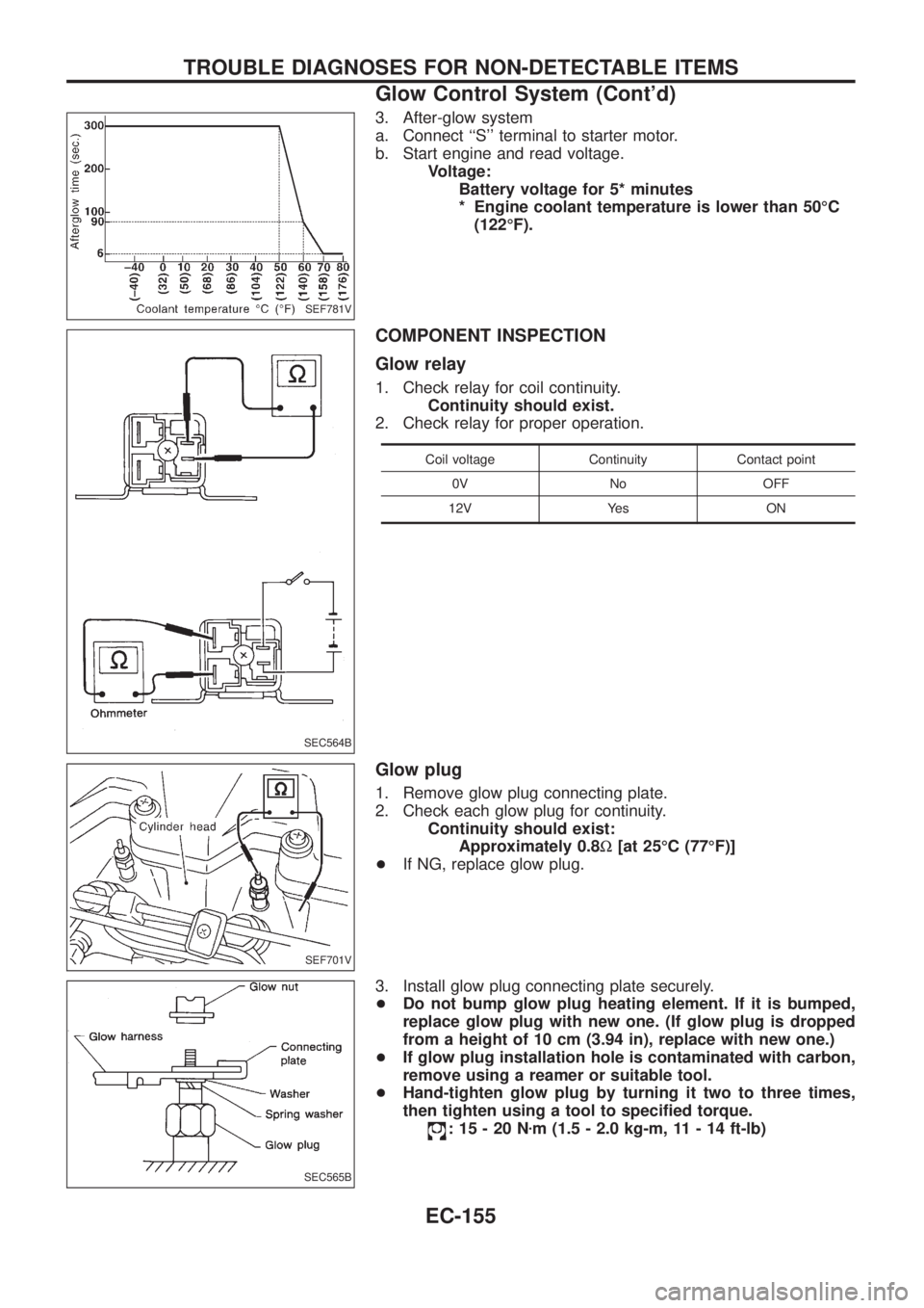
3. After-glow system
a. Connect ``S'' terminal to starter motor.
b. Start engine and read voltage.
Voltage:
Battery voltage for 5* minutes
* Engine coolant temperature is lower than 50ÉC
(122ÉF).
COMPONENT INSPECTION
Glow relay
1. Check relay for coil continuity.
Continuity should exist.
2. Check relay for proper operation.
Coil voltage Continuity Contact point
0V No OFF
12V Yes ON
Glow plug
1. Remove glow plug connecting plate.
2. Check each glow plug for continuity.
Continuity should exist:
Approximately 0.8W[at 25ÉC (77ÉF)]
+If NG, replace glow plug.
3. Install glow plug connecting plate securely.
+Do not bump glow plug heating element. If it is bumped,
replace glow plug with new one. (If glow plug is dropped
from a height of 10 cm (3.94 in), replace with new one.)
+If glow plug installation hole is contaminated with carbon,
remove using a reamer or suitable tool.
+Hand-tighten glow plug by turning it two to three times,
then tighten using a tool to speci®ed torque.
:15-20Nzm (1.5 - 2.0 kg-m, 11 - 14 ft-lb)
SEF781V
SEC564B
SEF701V
SEC565B
TROUBLE DIAGNOSES FOR NON-DETECTABLE ITEMS
Glow Control System (Cont'd)
EC-155