2006 NISSAN PATROL propeller shaft
[x] Cancel search: propeller shaftPage 1 of 1226

Edition: February 1998
Release: February 1998 (01)
Publication No.: SM8E-0Y61E0E
Reference No.: 7711346063GENERAL INFORMATIONGI
MAINTENANCEMA
ENGINE MECHANICALEM
ENGINE LUBRICATION &
COOLING SYSTEMSLC
ENGINE CONTROL SYSTEMEC
ACCELERATOR CONTROL,
FUEL & EXHAUST SYSTEMFE
CLUTCHCL
MANUAL TRANSMISSIONMT
AUTOMATIC TRANSMISSIONAT
TRANSFERTF
PROPELLER SHAFT &
DIFFERENTIAL CARRIERPD
FRONT AXLE & FRONT SUSPENSIONFA
REAR AXLE & REAR SUSPENSIONRA
BRAKE SYSTEMBR
STEERING SYSTEMST
RESTRAINT SYSTEMRS
BODY & TRIMBT
HEATER & AIR CONDITIONERHA
ELECTRICAL SYSTEMEL
ALPHABETICAL INDEXIDX
PATROL GR
MODEL Y61 SERIES
NISSAN EUROPE S.A.S.
1998 NISSAN EUROPE S.A.S.
Produced in The Netherlands
Not to be reproduced in whole or in part
without the prior written permission of
Nissan Europe S.A.S., Paris, France.
QUICK REFERENCE INDEX
Page 6 of 1226
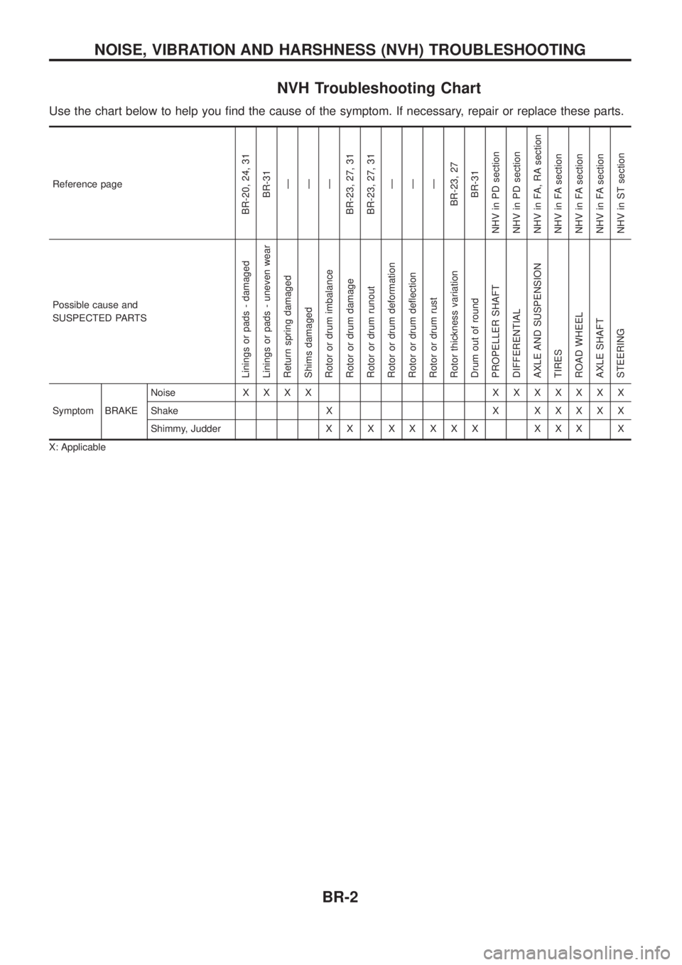
NVH Troubleshooting Chart
Use the chart below to help you ®nd the cause of the symptom. If necessary, repair or replace these parts.
Reference page
BR-20, 24, 31BR-31Ð
Ð
Ð
BR-23, 27, 31
BR-23, 27, 31 Ð
Ð
Ð
BR-23, 27 BR-31
NHV in PD section
NHV in PD section
NHV in FA, RA section
NHV in FA section
NHV in FA section
NHV in FA section
NHV in ST section
Possible cause and
SUSPECTED PARTS
Linings or pads - damaged
Linings or pads - uneven wear
Return spring damaged
Shims damaged
Rotor or drum imbalance
Rotor or drum damage
Rotor or drum runout
Rotor or drum deformation
Rotor or drum de¯ection
Rotor or drum rust
Rotor thickness variation
Drum out of round
PROPELLER SHAFT
DIFFERENTIAL
AXLE AND SUSPENSION
TIRES
ROAD WHEEL
AXLE SHAFT
STEERING
Symptom BRAKE Noise
XXXX XXXXXXX
Shake X X X X X X X
Shimmy, Judder X X XXXXXX XXX X
X: Applicable
NOISE, VIBRATION AND HARSHNESS (NVH) TROUBLESHOOTING
BR-2
Page 35 of 1226
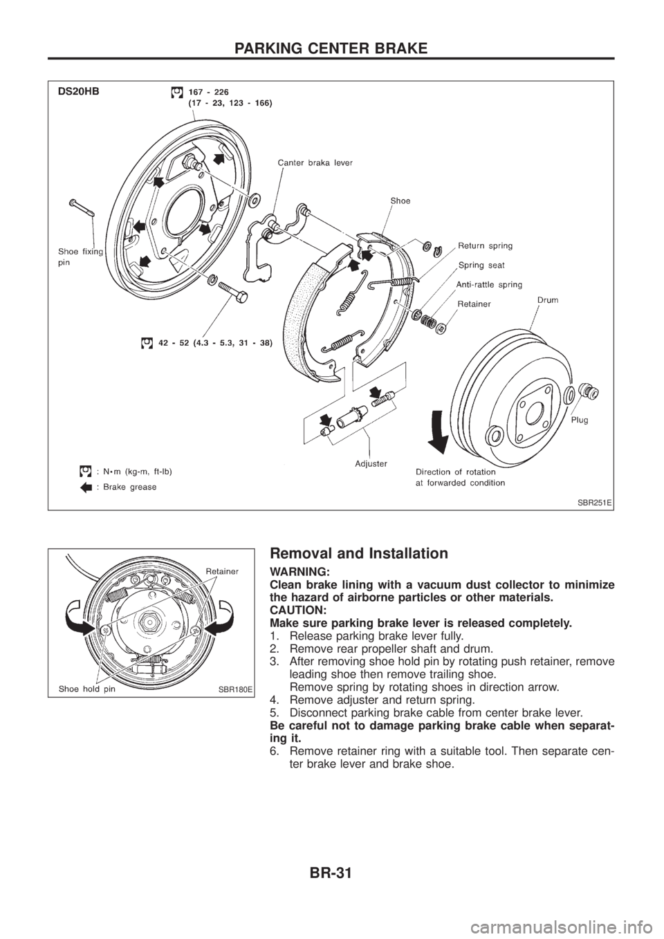
Removal and Installation
WARNING:
Clean brake lining with a vacuum dust collector to minimize
the hazard of airborne particles or other materials.
CAUTION:
Make sure parking brake lever is released completely.
1. Release parking brake lever fully.
2. Remove rear propeller shaft and drum.
3. After removing shoe hold pin by rotating push retainer, removeleading shoe then remove trailing shoe.
Remove spring by rotating shoes in direction arrow.
4. Remove adjuster and return spring.
5. Disconnect parking brake cable from center brake lever.
Be careful not to damage parking brake cable when separat-
ing it.
6. Remove retainer ring with a suitable tool. Then separate cen- ter brake lever and brake shoe.
SBR251E
SBR180E
PARKING CENTER BRAKE
BR-31
Page 736 of 1226
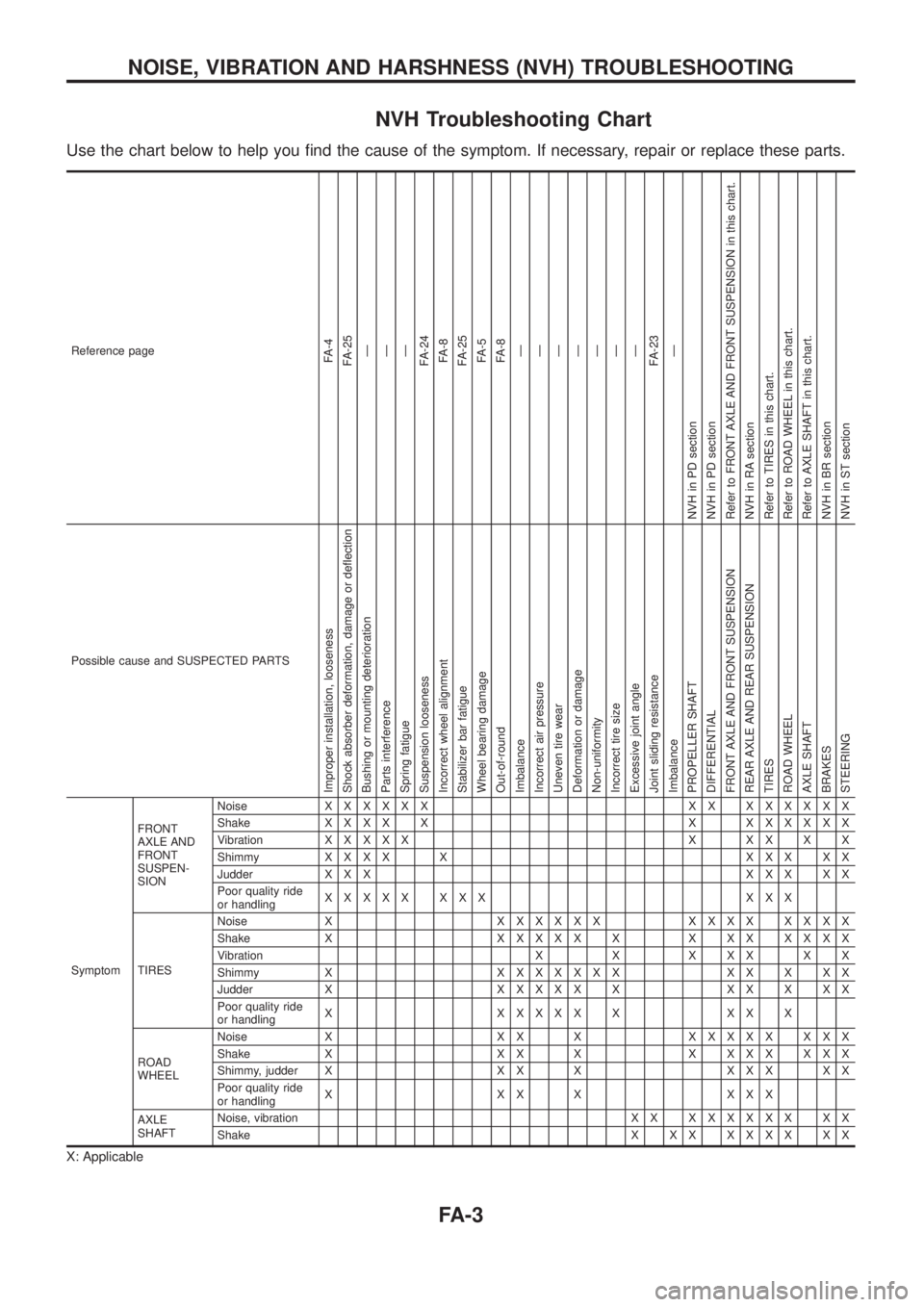
NVH Troubleshooting Chart
Use the chart below to help you ®nd the cause of the symptom. If necessary, repair or replace these parts.
Reference pageFA-4
FA-25
Ð
Ð
Ð
FA-24
FA-8
FA-25
FA-5
FA-8
Ð
Ð
Ð
Ð
Ð
Ð
Ð
FA-23
Ð
NVH in PD section
NVH in PD section
Refer to FRONT AXLE AND FRONT SUSPENSION in this chart.
NVH in RA section
Refer to TIRES in this chart.
Refer to ROAD WHEEL in this chart.
Refer to AXLE SHAFT in this chart.
NVH in BR section
NVH in ST section
Possible cause and SUSPECTED PARTS
Improper installation, looseness
Shock absorber deformation, damage or de¯ection
Bushing or mounting deterioration
Parts interference
Spring fatigue
Suspension looseness
Incorrect wheel alignment
Stabilizer bar fatigue
Wheel bearing damage
Out-of-round
Imbalance
Incorrect air pressure
Uneven tire wear
Deformation or damage
Non-uniformity
Incorrect tire size
Excessive joint angle
Joint sliding resistance
Imbalance
PROPELLER SHAFT
DIFFERENTIAL
FRONT AXLE AND FRONT SUSPENSION
REAR AXLE AND REAR SUSPENSION
TIRES
ROAD WHEEL
AXLE SHAFT
BRAKES
STEERING
SymptomFRONT
AXLE AND
FRONT
SUSPEN-
SIONNoiseXXXXXX XX XXXXXX
ShakeXXXX X X XXXXXX
VibrationXXXXX X XX X X
ShimmyXXXX X XXX XX
Judder X X XXXX XX
Poor quality ride
or handlingXXXXX XXX XXX
TIRESNoise XXXXXXX XXXX XXXX
Shake XXXXXX X X XX XXXX
Vibration X X X X X X X
Shimmy XXXXXXXX XX X XX
Judder XXXXXX X XX X XX
Poor quality ride
or handlingX XXXXX X XX X
ROAD
WHEELNoise X X X XXXXXX XXX
Shake X X X X X X X X X X X
Shimmy, judder X X X X X X X X X
Poor quality ride
or handlingX XX X XXX
AXLE
SHAFTNoise, vibration X XXXXXXX XX
ShakeX XX XXXX XX
X: Applicable
NOISE, VIBRATION AND HARSHNESS (NVH) TROUBLESHOOTING
FA-3
Page 815 of 1226
If you have to tow an automatic transmission model
with four wheels on ground or tow an automatic
transmission model with front wheels raised (with rear
wheels on ground)
Observe the following restricted towing speeds, distances and rais-
ing heights.
+Speed: Below 50 km/h (30 MPH)
+Distance: Less than 65 km (40 miles)
+Do not raise the front end over!.
Wagon
!= 600 mm (23.62 in)
Hardtop
!= 500 mm (19.69 in)
If the speed, distance or height must necessarily be greater,
remove the propeller shaft beforehand to prevent damage to the
transmission.
CAUTION:
+Never tow your vehicle from the rear (i.e., backward) with
four wheels on the ground as this may cause serious and
expensive damage to the transmission.
+Be sure to place the transfer case shift lever into the ``2H''
position and the transmission shift lever into the neutral
(``N'') position if the vehicle is to be towed.
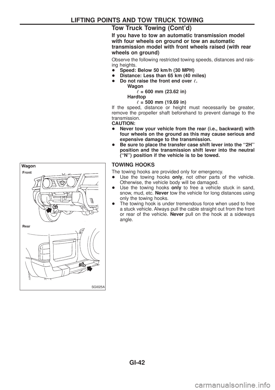
TOWING HOOKS
The towing hooks are provided only for emergency.
+Use the towing hooksonly, not other parts of the vehicle.
Otherwise, the vehicle body will be damaged.
+Use the towing hooksonlyto free a vehicle stuck in sand,
snow, mud, etc.Nevertow the vehicle for long distances using
only the towing hooks.
+The towing hook is under tremendous force when used to free
a stuck vehicle. Always pull the cable straight out from the front
or rear of the vehicle.Neverpull on the hook at a sideways
angle.
SGI025A
LIFTING POINTS AND TOW TRUCK TOWING
Tow Truck Towing (Cont'd)
GI-42
Page 951 of 1226

Front drive shaft (Transfer) .............................TF-11
Front ®nal drive disassembly (4WD) ..............PD-14
Front ®nal drive removal and installa-
tion (4WD)...................................................PD-11
Front passenger air bag.............................RS-8, 14
Front seat belt ..................................................RS-2
Front seat ........................................................BT-32
Front suspension ............................................FA-24
Front washer .................................................EL-141
Front wiper ....................................................EL-141
Fuel cut control (at no load & high
engine speed) .............................................EC-20
Fuel cut solenoid valve ................................EC-129
Fuel ®ller lid.......................................................BT-6
Fuel ®lter replacement ...................................MA-16
Fuel gauge ....................................................EL-102
Fuel injection system......................................EC-15
Fuel line inspection ........................................MA-17
Fuel precautions ................................................GI-5
Fuel temperature sensor ..............................EC-134
Fuse block.....................................................EL-319
Fuse ................................................................EL-14
Fusible link ......................................................EL-14
G
GLOW - Wiring diagram...............................EC-150
GOVNR - Wiring diagram ..............................EC-95
Garage jack and safety stand .........................GI-39
Gauges..........................................................EL-102
Gear components (M/T) .................................MT-10
Glass .................................................................BT-9
Glow plug .............................................EC-150, 154
Glow relay ............................................EC-150, 154
Grease .............................................................MA-9
Ground distribution..........................................EL-15
H
H/AIM - Wiring diagram ..................................EL-71
H/LAMP - Wiring diagram ...............................EL-61
HEAT UP - Wiring diagram ..........................EC-182
HFC134a (R134a) system service
procedure ..................................................HA-112
HLC - Wiring diagram ...................................EL-153
HORN - Wiring diagram................................EL-155
Harness connector inspection .........................GI-17
Harness connector ............................................EL-2
Harness layout ..............................................EL-275
Headlamp aiming control ................................EL-70
Headlamp leveler - See Headlamp
aiming control ..............................................EL-70
Headlamp wiper ............................................EL-153
Headlamp ........................................................EL-61
Headlining - See Roof trim .............................BT-20
Heat up switch..............................................EC-182
Heated seat.....................................................BT-34Hood..................................................................BT-4
Horn ..............................................................EL-155
How to erase DTC for ECCS OBD
system ........................................................EC-30
I
IATS - Wiring diagram ..................................EC-121
IC/FAN - Wiring diagram ..............................EC-177
ILL - Wiring diagram .......................................EL-87
INT/L - Wiring diagram..................................EL-101
Identi®cation plate............................................GI-37
Idle speed inspection .....................................MA-19
Idle speed .......................................................EC-46
Illumination ......................................................EL-86
In vehicle sensor ..........................................HA-105
Injection nozzle inspection .............................MA-18
Injection nozzle...............................................EC-22
Injection timing control valve ........................EC-100
Instrument panel .............................................BT-11
Intake door control linkage adjustment ..........HA-84
Intake door motor ...........................................HA-25
Intake sensor ................................................HA-111
Interior lamp ....................................................EL-93
Interior .............................................................BT-14
J
Jacking points ..................................................GI-39
Joint connector (J/C).....................................EL-322
Journal bearing assembly (propeller
shaft) .............................................................PD-8
Journal bearing disassembly (propeller
shaft) .............................................................PD-7
Junction box (J/B) .........................................EL-319
L
LSV (Load sensing valve) ................................BR-6
Lifting points ....................................................GI-40
Limited slip diff. adjustment............................PD-23
Limited slip diff. assembly ..............................PD-24
Limited slip diff. disassembly .........................PD-21
Limited slip diff. inspection .............................PD-21
Location of electrical units ............................EL-269
Lock, door .........................................................BT-9
Lubricant (R134a) A/C ..................................HA-114
Lubricants.........................................................MA-9
Lubrication circuit (engine) ...............................LC-3
Lubrication-locks, hinges and hood
latches ........................................................MA-27
Luggage compartment trim .............................BT-14
Luggage room lamp ........................................EL-93
ALPHABETICAL INDEX
IDX-4
Page 952 of 1226
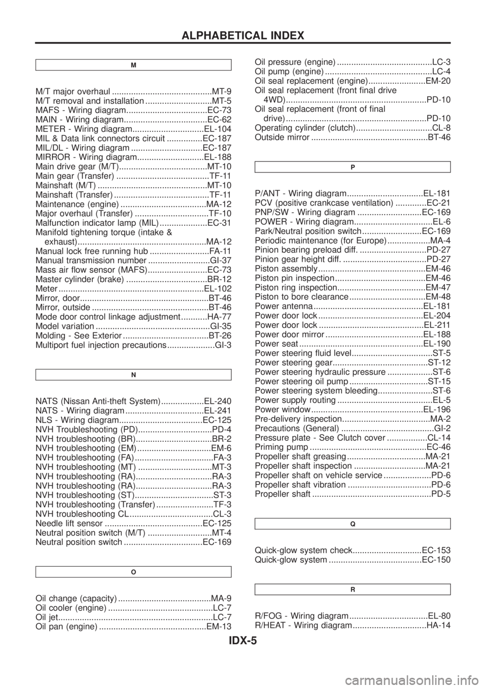
M
M/T major overhaul ..........................................MT-9
M/T removal and installation ............................MT-5
MAFS - Wiring diagram..................................EC-73
MAIN - Wiring diagram...................................EC-62
METER - Wiring diagram..............................EL-104
MIL & Data link connectors circuit ...............EC-187
MIL/DL - Wiring diagram ..............................EC-187
MIRROR - Wiring diagram............................EL-188
Main drive gear (M/T).....................................MT-10
Main gear (Transfer) .......................................TF-11
Mainshaft (M/T) ..............................................MT-10
Mainshaft (Transfer) ........................................TF-11
Maintenance (engine) ....................................MA-12
Major overhaul (Transfer) ...............................TF-10
Malfunction indicator lamp (MIL) ....................EC-31
Manifold tightening torque (intake &
exhaust)......................................................MA-12
Manual lock free running hub .........................FA-11
Manual transmission number ..........................GI-37
Mass air ¯ow sensor (MAFS).........................EC-73
Master cylinder (brake) ..................................BR-12
Meter .............................................................EL-102
Mirror, door......................................................BT-46
Mirror, outside .................................................BT-46
Mode door control linkage adjustment ...........HA-77
Model variation ................................................GI-35
Molding - See Exterior ....................................BT-26
Multiport fuel injection precautions ....................GI-3
N
NATS (Nissan Anti-theft System)..................EL-240
NATS - Wiring diagram .................................EL-241
NLS - Wiring diagram...................................EC-125
NVH Troubleshooting (PD)...............................PD-4
NVH troubleshooting (BR)................................BR-2
NVH troubleshooting (EM) ...............................EM-6
NVH troubleshooting (FA) .................................FA-3
NVH troubleshooting (MT) ...............................MT-3
NVH troubleshooting (RA)................................RA-3
NVH troubleshooting (RA)................................RA-3
NVH troubleshooting (ST).................................ST-3
NVH troubleshooting (Transfer) ........................TF-3
NVH troubleshooting CL ...................................CL-3
Needle lift sensor .........................................EC-125
Neutral position switch (M/T) ...........................MT-4
Neutral position switch .................................EC-169
O
Oil change (capacity) .......................................MA-9
Oil cooler (engine) ............................................LC-7
Oil jet.................................................................LC-7
Oil pan (engine) .............................................EM-13Oil pressure (engine) ........................................LC-3
Oil pump (engine) .............................................LC-4
Oil seal replacement (engine)........................EM-20
Oil seal replacement (front ®nal drive
4WD)...........................................................PD-10
Oil seal replacement (front of ®nal
drive) ...........................................................PD-10
Operating cylinder (clutch)................................CL-8
Outside mirror .................................................BT-46
P
P/ANT - Wiring diagram................................EL-181
PCV (positive crankcase ventilation) .............EC-21
PNP/SW - Wiring diagram ...........................EC-169
POWER - Wiring diagram.................................EL-6
Park/Neutral position switch .........................EC-169
Periodic maintenance (for Europe) ..................MA-4
Pinion bearing preload diff. ............................PD-27
Pinion gear height diff. ...................................PD-27
Piston assembly .............................................EM-46
Piston pin inspection ......................................EM-46
Piston ring inspection.....................................EM-47
Piston to bore clearance ................................EM-48
Power antenna ..............................................EL-181
Power door lock ............................................EL-204
Power door lock ............................................EL-211
Power door mirror .........................................EL-188
Power seat ....................................................EL-190
Power steering ¯uid level..................................ST-5
Power steering gear........................................ST-12
Power steering hydraulic pressure ...................ST-6
Power steering oil pump .................................ST-15
Power steering system bleeding.......................ST-6
Power supply routing ........................................EL-5
Power window ...............................................EL-196
Pre-delivery inspection.....................................MA-2
Precautions (General) .......................................GI-2
Pressure plate - See Clutch cover .................CL-14
Priming pump .................................................EC-46
Propeller shaft greasing .................................MA-21
Propeller shaft inspection ..............................MA-21
Propeller shaft on vehicle service ....................PD-6
Propeller shaft vibration ...................................PD-6
Propeller shaft ..................................................PD-5
Q
Quick-glow system check.............................EC-153
Quick-glow system .......................................EC-150
R
R/FOG - Wiring diagram .................................EL-80
R/HEAT - Wiring diagram ...............................HA-14
ALPHABETICAL INDEX
IDX-5
Page 977 of 1226
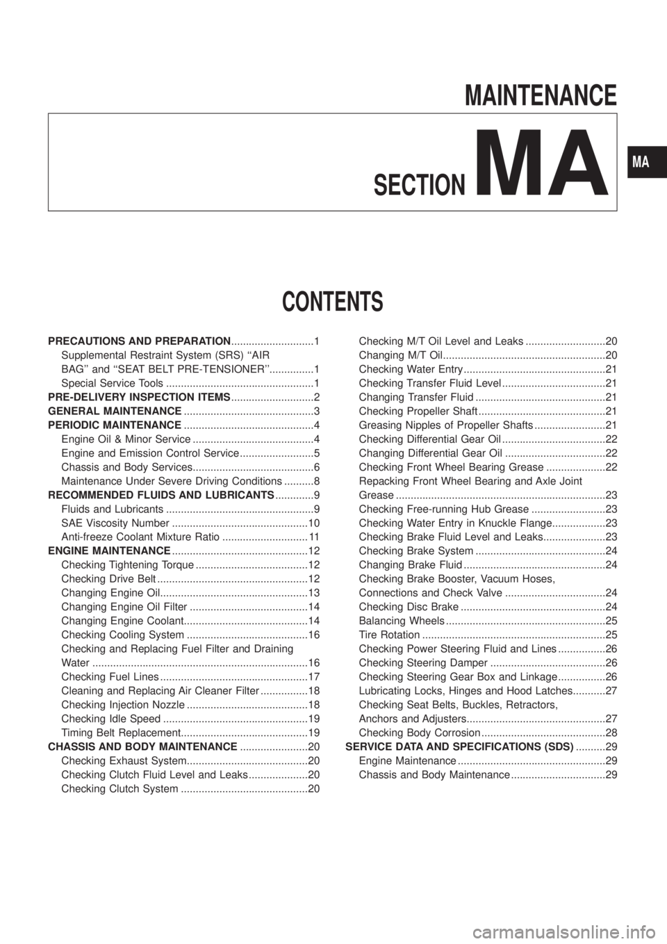
MAINTENANCE
SECTION
MA
CONTENTS
PRECAUTIONS AND PREPARATION............................1
Supplemental Restraint System (SRS) ``AIR
BAG'' and ``SEAT BELT PRE-TENSIONER''...............1
Special Service Tools ..................................................1
PRE-DELIVERY INSPECTION ITEMS............................2
GENERAL MAINTENANCE............................................3
PERIODIC MAINTENANCE............................................4
Engine Oil & Minor Service .........................................4
Engine and Emission Control Service .........................5
Chassis and Body Services.........................................6
Maintenance Under Severe Driving Conditions ..........8
RECOMMENDED FLUIDS AND LUBRICANTS.............9
Fluids and Lubricants ..................................................9
SAE Viscosity Number ..............................................10
Anti-freeze Coolant Mixture Ratio ............................. 11
ENGINE MAINTENANCE..............................................12
Checking Tightening Torque ......................................12
Checking Drive Belt ...................................................12
Changing Engine Oil..................................................13
Changing Engine Oil Filter ........................................14
Changing Engine Coolant..........................................14
Checking Cooling System .........................................16
Checking and Replacing Fuel Filter and Draining
Water .........................................................................16
Checking Fuel Lines ..................................................17
Cleaning and Replacing Air Cleaner Filter ................18
Checking Injection Nozzle .........................................18
Checking Idle Speed .................................................19
Timing Belt Replacement...........................................19
CHASSIS AND BODY MAINTENANCE.......................20
Checking Exhaust System.........................................20
Checking Clutch Fluid Level and Leaks ....................20
Checking Clutch System ...........................................20Checking M/T Oil Level and Leaks ...........................20
Changing M/T Oil.......................................................20
Checking Water Entry ................................................21
Checking Transfer Fluid Level ...................................21
Changing Transfer Fluid ............................................21
Checking Propeller Shaft ...........................................21
Greasing Nipples of Propeller Shafts ........................21
Checking Differential Gear Oil ...................................22
Changing Differential Gear Oil ..................................22
Checking Front Wheel Bearing Grease ....................22
Repacking Front Wheel Bearing and Axle Joint
Grease .......................................................................23
Checking Free-running Hub Grease .........................23
Checking Water Entry in Knuckle Flange..................23
Checking Brake Fluid Level and Leaks.....................23
Checking Brake System ............................................24
Changing Brake Fluid ................................................24
Checking Brake Booster, Vacuum Hoses,
Connections and Check Valve ..................................24
Checking Disc Brake .................................................24
Balancing Wheels ......................................................25
Tire Rotation ..............................................................25
Checking Power Steering Fluid and Lines ................26
Checking Steering Damper .......................................26
Checking Steering Gear Box and Linkage ................26
Lubricating Locks, Hinges and Hood Latches...........27
Checking Seat Belts, Buckles, Retractors,
Anchors and Adjusters...............................................27
Checking Body Corrosion ..........................................28
SERVICE DATA AND SPECIFICATIONS (SDS)..........29
Engine Maintenance ..................................................29
Chassis and Body Maintenance ................................29
MA