Page 398 of 1226

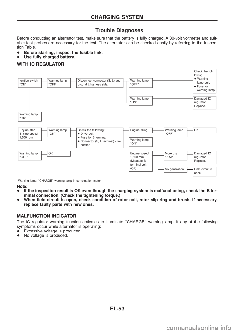
Trouble Diagnoses
Before conducting an alternator test, make sure that the battery is fully charged. A 30-volt voltmeter and suit-
able test probes are necessary for the test. The alternator can be checked easily by referring to the Inspec-
tion Table.
+Before starting, inspect the fusible link.
+Use fully charged battery.
WITH IC REGULATOR
Check the fol-
lowing:
+Warning
lamp bulb
+Fuse for
warning lamp
Ignition switch
``ON''Warning lamp
``OFF''Disconnect connector (S, L) and
ground L harness side.Warning lamp
``OFF''
Warning lamp
``ON''Damaged IC
regulator.
Replace.
Warning lamp
``ON''
Engine start.
Engine speed:
1,500 rpmWarning lamp
``ON''Check the following:
+Drive belt
+Fuse for S terminal
+Connector (S, L terminal) con-
nectionEngine idlingWarning lamp
``OFF''OK
Warning lamp
``ON''
Warning lamp
``OFF''OKEngine speed:
1,500 rpm
(Measure B
terminal volt-
age)More than
15.5VDamaged IC
regulator.
Replace.
No generationField circuit is
open.
Warning lamp: ``CHARGE'' warning lamp in combination meter
Note:
+If the inspection result is OK even though the charging system is malfunctioning, check the B ter-
minal connection. (Check the tightening torque.)
+When ®eld circuit is open, check condition of rotor coil, rotor slip ring and brush. If necessary,
replace faulty parts with new ones.
MALFUNCTION INDICATOR
The IC regulator warning function activates to illuminate ``CHARGE'' warning lamp, if any of the following
symptoms occur while alternator is operating:
+Excessive voltage is produced.
+No voltage is produced.
CHARGING SYSTEM
EL-53
Page 684 of 1226
CAUTION:
+Do not bend or twist timing belt.
+After removing timing belt, do not turn crankshaft and
camshaft separately because valves will strike piston
heads.
+Make sure that timing belt, camshaft sprocket, crankshaft
sprocket, idler pulley, injection pump pulley and belt ten-
sioner are clean and free from oil and water.
+Align white lines on timing belt with punch mark on cam-
shaft sprocket, crankshaft sprocket and injection pump
pulley.
+Installation should be carried out when engine is cold.
Removal
1. Remove radiator shroud.
2. Remove the following belts.
+Power steering drive belt
+A/C compressor drive belt
+Alternator drive belt
3. Remove cooling fan coupling and water pump pulley.
SMA767BA
TIMING BELT
EM-16
Page 713 of 1226
Removal
1. Remove engine, transmission and transfer's undercovers, oil
pan guard and hood.
2. Drain engine coolant.
3. Remove charge air cooler assembly.
4. Remove vacuum hoses, fuel tubes, harnesses, and connectors
and so on.
5. Remove radiator assembly.
6. Remove drive belts.
7. Remove power steering oil pump, alternator and air conditioner
compressor.
8. Remove starter motor assembly.
9. Remove front exhaust tube.
10. Remove transmission from vehicle.
Refer to MT section.
11. Hoist engine with engine slingers and remove engine mounting
bolts from both sides.
12. Remove engine from vehicle.
Installation
+Install in reverse order of removal.
ENGINE REMOVAL
EM-45
Page 990 of 1226

1. Inspect for cracks, fraying, wear or oil adhesion. Replace if
necessary.
The belts should not touch the bottom of the pulley groove.
2. Check drive belt de¯ection by pushing on the belt midway
between pulleys.
Adjust if belt de¯ections exceed the limit.
Unit: mm (in)
Used belt de¯ection
De¯ection of new belt
LimitDe¯ection after
adjustment
Alternator 17 (0.67) 12 - 14 (0.47 - 0.55) 9 - 11 (0.35 - 0.43)
Air conditioner
compressor11 (0.43)7 - 9 (0.28 - 0.35)6 - 8 (0.24 - 0.31)
Power steering oil
pump14 (0.55) 10 - 12 (0.39 - 0.47) 9 - 11 (0.35 - 0.43)
Applied pushing
force98 N (10 kg, 22 lb)
Check drive belt de¯ections when engine is cold.
Changing Engine Oil
WARNING:
+Be careful not to burn yourself, as engine oil is hot.
+Prolonged and repeated contact with used engine oil may
cause skin cancer; try to avoid direct skin contact with
used oil. If skin contact is made, wash thoroughly with
soap or hand cleaner as soon as possible.
1. Warm up engine, and check for oil leakage from engine com-
ponents.
2. Remove oil ®ller cap and drain plug.
3. Drain oil and ®ll with new engine oil.
Oil grade: CCMC PD1 or PD2
Viscosity:
See ``RECOMMENDED FLUIDS AND
LUBRICANTS'', MA-9.
Re®ll oil capacity (approximate):
Without oil ®lter change
6.4!(5-5/8 Imp qt)
With oil ®lter change
5.8!(5-1/8 Imp qt)
CAUTION:
+Be sure to clean and install oil pan drain plug with washer.
Drain plug:
:29-39Nzm (3.0 - 4.0 kg-m, 22 - 29 ft-lb)
+The re®ll capacity changes depending on the oil tempera-
ture and drain time; use these valves as a reference and be
certain to check with the dipstick when changing the oil.
SMA998C
ENGINE MAINTENANCE
Checking Drive Belt (Cont'd)
MA-13
Page 1006 of 1226
Engine Maintenance
INSPECTION AND ADJUSTMENT
Drive belt de¯ection
Unit: mm (in)
Drive beltsUsed belt de¯ection
De¯ection of
new belt
LimitDe¯ection
after adjust-
ment
Alternator
With air condi-
tioner compressor17 (0.67)12-14
(0.47 - 0.55)9-11
(0.35 - 0.43)
Without air condi-
tioner compressor11 (0.43)7-9
(0.28 - 0.35)6-8
(0.24 - 0.31)
Power steering oil
pump14 (0.55)10-12
(0.39 - 0.47)9-11
(0.35 - 0.43)
Applied pushing force 98 N (10 kg, 22 lb)
Engine oil capacity (Re®ll capacity)
Unit:!(Imp qt)
With oil ®lter change 6.4 (5-5/8)
Without oil ®lter change 5.8 (5-1/8)
Coolant capacity (Re®ll capacity)
With reservoir tank
Unit:!(Imp qt)
With rear heater Without rear heater
RHD 12.9 (11-3/8) 11.8 (10-3/8)
LHD 12.7 (11-1/8) 11.6 (10-1/4)
Reservoir tank 2.4 (2-1/8)
Chassis and Body Maintenance
INSPECTION AND ADJUSTMENT
Wheel balance
Maximum allowable
unbalanceDynamic
(At rim ¯ange)
g (oz)10 (0.35) (one side)
Static g (oz) 20 (0.71)
SERVICE DATA AND SPECIFICATIONS (SDS)
MA-29