2006 NISSAN PATROL glove box
[x] Cancel search: glove boxPage 89 of 1226

CAUTION:
+Disconnect both battery cables in advance.
+Disconnect air bag system line in advance.
+Never tamper with or force air bag lid open, as this may adversely affect air bag performance.
+Be careful not to scratch pad and other parts.
REMOVAL Ð Instrument panel assembly
Instrument panel assemblyCombination meterAudio & A/C controlConsole box
Remove air bag module (driver) and steering wheel.
Refer to ``SUPPLEMENTAL RESTRAINT SYSTEM'' in RS section for details.
Remove dash side lower ®nishers.
Refer to ``Side and Floor Trim'' in ``INTERIOR TRIM'' for
details, BT-14.
V1Steering column cover and combination switch
+Remove screws.
V2Lower instrument panel on driver side
+Remove bolts and screws.
V3Cluster lid A
+Remove screws then disconnect harness connectors.
V4Combination meter
+Remove screws then disconnect harness connectors.
V5Cluster lid C
+Pull out then disconnect harness connectors.
+Remove screws then remove in-vehicle sensor.
V6Audio
+Remove screws then disconnect harness connectors.
V7A/C control unit
+Remove screws then disconnect harness connectors.
V8Console M/T or A/T ®nisher
+Remove screws then disconnect harness connectors.
V9Console box assembly
+Remove screws then disconnect harness connectors.
V10Instrument panel stay cover
+Remove screws then disconnect harness con-
nectors.
V11Glove box assembly and lower instrument panel on
passenger side
+Remove screws.
V12Passenger air bag module
+Refer to ``SUPPLEMENTAL RESTRAINT SYS-
TEM'' in RS section.
V13Mirror control switch
+Disconnect harness connector.
Remove front pillar garnish.
Refer to ``Side and Floor Trim'' in ``INTERIOR TRIM'' for
details, BT-14.
V14Mask instrument LH/RH or sensors.
+Disconnect harness connectors (models with
sensors).
V15Instrument panel and pads
+Remove bolts and nuts then disconnect harness
connectors.
INSTRUMENT PANEL
BT-11
Page 120 of 1226

REMOVAL
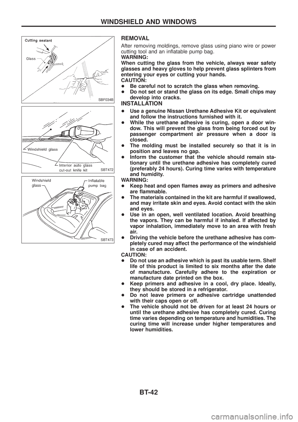
After removing moldings, remove glass using piano wire or power
cutting tool and an in¯atable pump bag.
WARNING:
When cutting the glass from the vehicle, always wear safety
glasses and heavy gloves to help prevent glass splinters from
entering your eyes or cutting your hands.
CAUTION:
+Be careful not to scratch the glass when removing.
+Do not set or stand the glass on its edge. Small chips may
develop into cracks.
INSTALLATION
+Use a genuine Nissan Urethane Adhesive Kit or equivalent
and follow the instructions furnished with it.
+While the urethane adhesive is curing, open a door win-
dow. This will prevent the glass from being forced out by
passenger compartment air pressure when a door is
closed.
+The molding must be installed securely so that it is in
position and leaves no gap.
+Inform the customer that the vehicle should remain sta-
tionary until the urethane adhesive has completely cured
(preferably 24 hours). Curing time varies with temperature
and humidity.
WARNING:
+Keep heat and open ¯ames away as primers and adhesive
are ¯ammable.
+The materials contained in the kit are harmful if swallowed,
and may irritate skin and eyes. Avoid contact with the skin
and eyes.
+Use in an open, well ventilated location. Avoid breathing
the vapors. They can be harmful if inhaled. If affected by
vapor inhalation, immediately move to an area with fresh
air.
+Driving the vehicle before the urethane adhesive has com-
pletely cured may affect the performance of the windshield
in case of an accident.
CAUTION:
+Do not use an adhesive which is past its usable term. Shelf
life of this product is limited to six months after the date
of manufacture. Carefully adhere to the expiration or
manufacture date printed on the box.
+Keep primers and adhesive in a cool, dry place. Ideally,
they should be stored in a refrigerator.
+Do not leave primers or adhesive cartridge unattended
with their caps open or off.
+The vehicle should not be driven for at least 24 hours or
until the urethane adhesive has completely cured. Curing
time varies depending on temperature and humidities. The
curing time will increase under higher temperatures and
lower humidities.
SBF034B
SBT472
SBT473
WINDSHIELD AND WINDOWS
BT-42
Page 937 of 1226

Ventilation Air Filter
FUNCTION
Air inside passenger compartment is kept clean at either recircula-
tion or fresh mode by installing ventilation air ®lter into cooling unit.
REPLACEMENT TIMING
Replace ventilation air ®lter.
Refer to ``PERIODIC MAINTENANCE'' in MA section.
Caution label is ®xed inside the glove box.
REPLACEMENT PROCEDURES
+Remove glove box.
+Remove instrument reinforcement from instrument panel.
+Remove ventilation air ®lter ®xed clip.
+Take out ventilation air ®lter from cooling unit.
+Replace with new one and reinstall on cooling unit.
+Reinstall instrument reinforcement, glove box and undercover.
RHA042G
SHA868E
RHA953F
SERVICE PROCEDURESMANUAL AND AUTO
HA-116
Page 1136 of 1226

CAUTION:
+Always place air bag module with pad side facing upward.
+Do not attempt to disassemble air bag module.
+The special bolts are coated with bonding agent. Do not
use old bolts after removal; replace with new ones.
+Replace air bag module if it has been dropped or sustained
an impact.
+Do not expose the air bag module to temperatures exceed-
ing 90ÉC (194ÉF).
+Do not allow oil, grease or water to come in contact with
the air bag module.
3. Set steering wheel in the neutral position.
4. Disconnect horn connector and remove nuts.
5. Using steering wheel puller, remove steering wheel. Be careful
not to over-tighten puller bolt on steering wheel.
CAUTION:
Do not tap or bump the steering wheel.
6. Remove steering column cover.
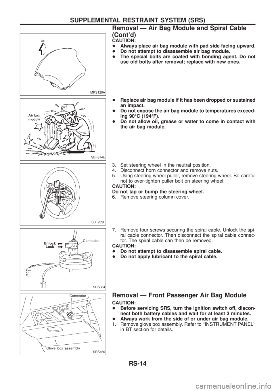
7. Remove four screws securing the spiral cable. Unlock the spi-
ral cable connector. Then disconnect the spiral cable connec-
tor. The spiral cable can then be removed.
CAUTION:
+Do not attempt to disassemble spiral cable.
+Do not apply lubricant to the spiral cable.
Removal Ð Front Passenger Air Bag Module
CAUTION:
+Before servicing SRS, turn the ignition switch off, discon-
nect both battery cables and wait for at least 3 minutes.
+Always work from the side of or under air bag module.
1. Remove glove box assembly. Refer to ``INSTRUMENT PANEL''
in BT section for details.
MRS120A
SBF814E
SBF239F
SRS384
SRS456
SUPPLEMENTAL RESTRAINT SYSTEM (SRS)
Removal Ð Air Bag Module and Spiral Cable
(Cont'd)
RS-14
Page 1139 of 1226

4. Install glove box assembly. (Glove box lid is open.)
5. Close the glove box lid.
Disposal of Air Bag Module and Seat Belt Pre-
tensioner
+Before disposing of air bag module and seat belt pre-tensioner, or vehicles equipped with such systems,
deploy the systems. If such systems have already been deployed due to an accident, dispose of as indi-
cated in ``DISPOSING OF AIR BAG MODULE AND SEAT BELT PRE-TENSIONER'' (RS-21).
+When deploying the air bag module, always use the Special Service Tool; Deployment tool KV99106400,
KV99108200 and KV99108300.
+When deploying the air bag module and seat belt pre-tensioner, stand at least 5 m (16 ft) away from the
deployment component.
+When deploying air bag module and seat belt pre-tensioner, a fairly loud noise is made, followed by smoke
being released. The smoke is not poisonous, however, be careful not to inhale smoke since it irritates throat
and can cause choking.
+Always activate one air bag module at a time.
+Due to heat, leave air bag module unattended for more than 30 minutes after deployment. Also leave seat
belt pre-tensioner unattended for more than 10 minutes after deployment.
+Be sure to wear gloves when handling a deployed air bag module.
+Never apply water to a deployed air bag module.
+Wash your hands clean after ®nishing work.
+Do not dispose of the air bag module un-deployed.
+Place the vehicle outdoors with an open space of at least 6 m (20 ft) on all sides when deploying the air
bag module while mounted in vehicle.
+Use a voltmeter to make sure the vehicle battery is fully charged.
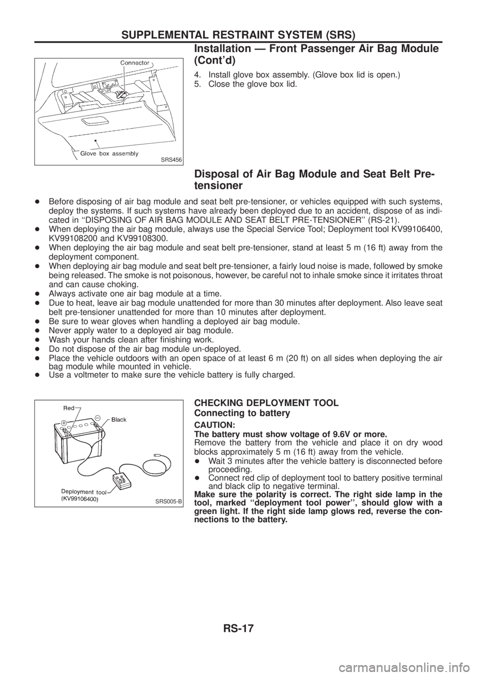
CHECKING DEPLOYMENT TOOL
Connecting to battery
CAUTION:
The battery must show voltage of 9.6V or more.
Remove the battery from the vehicle and place it on dry wood
blocks approximately 5 m (16 ft) away from the vehicle.
+Wait 3 minutes after the vehicle battery is disconnected before
proceeding.
+Connect red clip of deployment tool to battery positive terminal
and black clip to negative terminal.
Make sure the polarity is correct. The right side lamp in the
tool, marked ``deployment tool power'', should glow with a
green light. If the right side lamp glows red, reverse the con-
nections to the battery.
SRS456
SRS005-B
SUPPLEMENTAL RESTRAINT SYSTEM (SRS)
Installation Ð Front Passenger Air Bag Module
(Cont'd)
RS-17