2006 NISSAN PATROL fuse diagram
[x] Cancel search: fuse diagramPage 342 of 1226

ELECTRICAL SYSTEM
SECTION
EL
When you read wiring diagrams:
+Read GI section, ``HOW TO READ WIRING DIAGRAMS''.
When you perform trouble diagnoses, read GI section, ``HOW TO FOLLOW FLOW
CHART IN TROUBLE DIAGNOSES'' and ``HOW TO PERFORM EFFICIENT DIAGNOSIS
FOR AN ELECTRICAL INCIDENT''.
+Check for any service bulletins before servicing the vehicle.
CONTENTS
PRECAUTIONS...............................................................1
Supplemental Restraint System (SRS) ``AIR
BAG'' and ``SEAT BELT PRE-TENSIONER''...............1
HARNESS CONNECTOR................................................2
Description ...................................................................2
STANDARDIZED RELAY................................................3
Description ...................................................................3
POWER SUPPLY ROUTING...........................................5
Schematic ....................................................................5
Wiring Diagram Ð POWER Ð....................................6
Fuse ...........................................................................14
Fusible Link................................................................14
Circuit Breaker Inspection .........................................14
GROUND DISTRIBUTION/LHD MODELS....................15
Engine Room Harness ..............................................15
Main Harness.............................................................19
Body Harness ............................................................22
Body No. 2 Harness ..................................................23
Back Door and Rear Window Defogger Harness .....24
Room Lamp Harness.................................................25
GROUND DISTRIBUTION/RHD MODELS...................26
Engine Room Harness ..............................................26
Main Harness.............................................................30
Body Harness ............................................................33
Body No. 2 Harness ..................................................34
Back Door and Rear Window Defogger Harness .....35
Room Lamp Harness.................................................36
BATTERY.......................................................................37
How to Handle Battery ..............................................37
Battery Test and Charging Chart ...............................40
Service Data and Speci®cations (SDS).....................44
STARTING SYSTEM.....................................................45
Wiring Diagram Ð START Ð ....................................45Trouble Diagnoses.....................................................46
Construction ...............................................................47
Removal and Installation ...........................................47
Inspection...................................................................47
Assembly ...................................................................50
Service Data and Speci®cations (SDS).....................51
CHARGING SYSTEM....................................................52
Wiring Diagram Ð CHARGE Ð ................................52
Trouble Diagnoses.....................................................53
Construction ...............................................................54
Removal and Installation ...........................................54
Disassembly...............................................................54
Inspection...................................................................55
Assembly ...................................................................56
Service Data and Speci®cations (SDS).....................56
COMBINATION SWITCH...............................................57
Check .........................................................................57
Replacement ..............................................................58
STEERING SWITCH......................................................59
Check .........................................................................59
HEADLAMP Ð Conventional Type Ð........................61
Wiring Diagram Ð H/LAMP Ð ..................................61
Trouble Diagnoses.....................................................62
Bulb Replacement .....................................................63
Aiming Adjustment .....................................................63
HEADLAMP Ð Daytime Light System Ð..................65
System Description ....................................................65
Wiring Diagram Ð DTRL Ð ......................................67
Trouble Diagnoses.....................................................69
Bulb Replacement .....................................................69
Aiming Adjustment .....................................................69
HEADLAMP Ð Headlamp Aiming Control Ð............70
System Description ....................................................70
EL
Page 577 of 1226
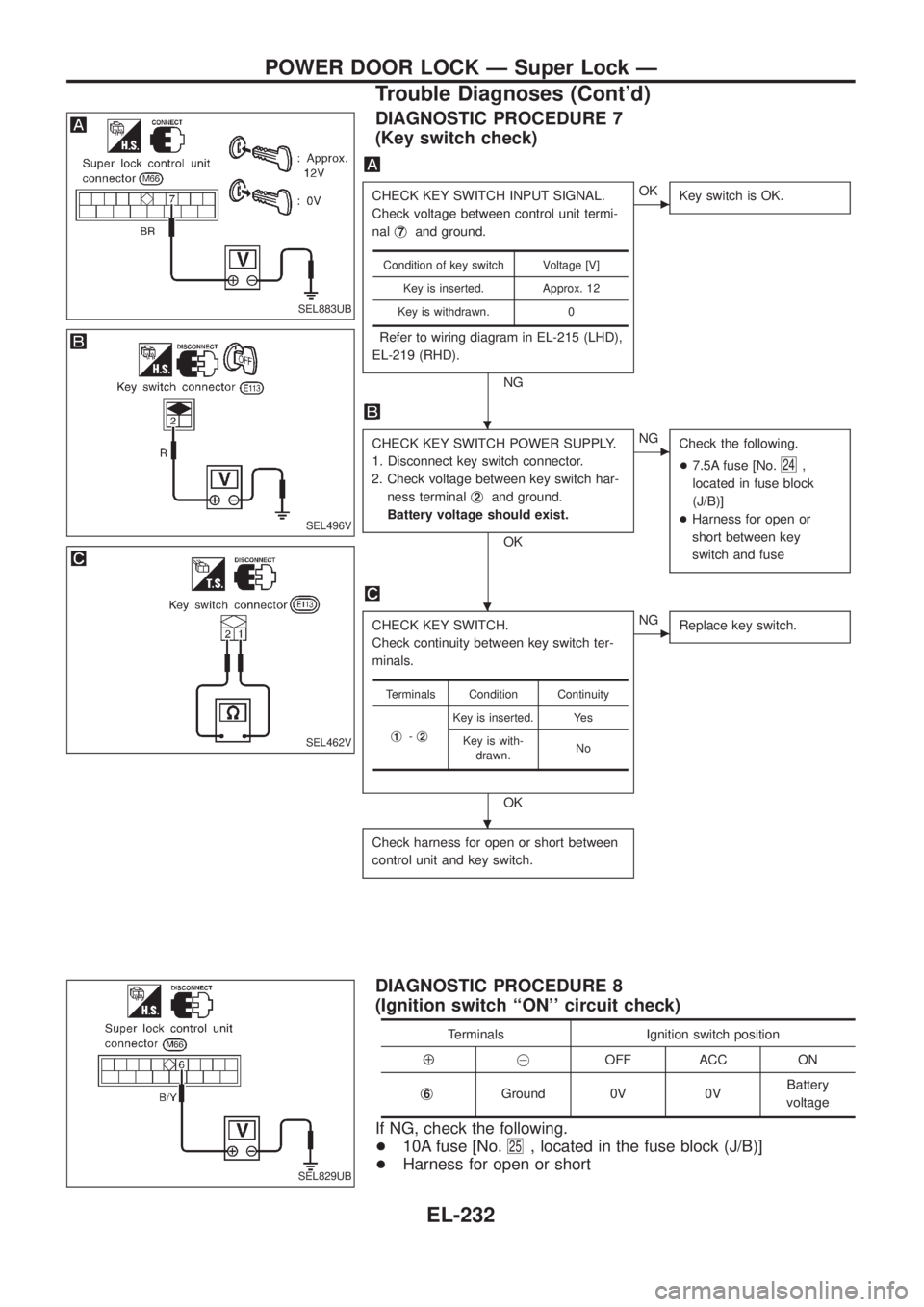
DIAGNOSTIC PROCEDURE 7
(Key switch check)
CHECK KEY SWITCH INPUT SIGNAL.
Check voltage between control unit termi-
nalj
7and ground.
Refer to wiring diagram in EL-215 (LHD),
EL-219 (RHD).
NG
cOK
Key switch is OK.
CHECK KEY SWITCH POWER SUPPLY.
1. Disconnect key switch connector.
2. Check voltage between key switch har-
ness terminalj
2and ground.
Battery voltage should exist.
OK
cNG
Check the following.
+7.5A fuse [No.
24,
located in fuse block
(J/B)]
+Harness for open or
short between key
switch and fuse
CHECK KEY SWITCH.
Check continuity between key switch ter-
minals.
OK
cNG
Replace key switch.
Check harness for open or short between
control unit and key switch.
Condition of key switch Voltage [V]
Key is inserted. Approx. 12
Key is withdrawn. 0
Terminals Condition Continuity
j
1-j2
Key is inserted. Yes
Key is with-
drawn.No
DIAGNOSTIC PROCEDURE 8
(Ignition switch ``ON'' circuit check)
Terminals Ignition switch position
Å@OFF ACC ON
j
6Ground 0V 0VBattery
voltage
If NG, check the following.
+10A fuse [No.
25, located in the fuse block (J/B)]
+Harness for open or short
SEL883UB
SEL496V
SEL462V
SEL829UB
.
.
.
POWER DOOR LOCK Ð Super Lock Ð
Trouble Diagnoses (Cont'd)
EL-232
Page 783 of 1226
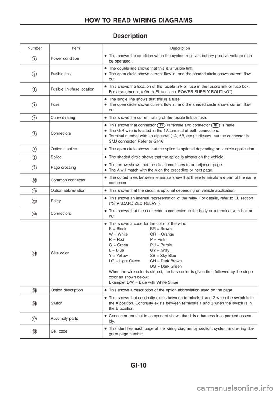
Description
Number Item Description
V1Power condition+This shows the condition when the system receives battery positive voltage (can
be operated).
V2Fusible link+The double line shows that this is a fusible link.
+The open circle shows current ¯ow in, and the shaded circle shows current ¯ow
out.
V3Fusible link/fuse location+This shows the location of the fusible link or fuse in the fusible link or fuse box.
For arrangement, refer to EL section (``POWER SUPPLY ROUTING'').
V4Fuse+The single line shows that this is a fuse.
+The open circle shows current ¯ow in, and the shaded circle shows current ¯ow
out.
V5Current rating+This shows the current rating of the fusible link or fuse.
V6Connectors+This shows that connector
E3is female and connectorM1is male.
+The G/R wire is located in the 1A terminal of both connectors.
+Terminal number with an alphabet (1A, 5B, etc.) indicates that the connector is
SMJ connector. Refer to GI-16.
V7Optional splice+The open circle shows that the splice is optional depending on vehicle application.
V8Splice+The shaded circle shows that the splice is always on the vehicle.
V9Page crossing+This arrow shows that the circuit continues to an adjacent page.
+The A will match with the A on the preceding or next page.
V10Common connector+The dotted lines between terminals show that these terminals are part of the same
connector.
V11Option abbreviation+This shows that the circuit is optional depending on vehicle application.
V12Relay+This shows an internal representation of the relay. For details, refer to EL section
(``STANDARDIZED RELAY'').
V13Connectors+This shows that the connector is connected to the body or a terminal with bolt or
nut.
V14Wire color+This shows a code for the color of the wire.
B = Black BR = Brown
W = White OR = Orange
R = Red P = Pink
G = Green PU = Purple
L = Blue GY = Gray
Y = Yellow SB = Sky Blue
LG = Light Green CH = Dark Brown
DG = Dark Green
When the wire color is striped, the base color is given ®rst, followed by the stripe
color as shown below:
Example: L/W = Blue with White Stripe
V15Option description+This shows a description of the option abbreviation used on the page.
V16Switch+This shows that continuity exists between terminals 1 and 2 when the switch is in
the A position. Continuity exists between terminals 1 and 3 when the switch is in
the B position.
V17Assembly parts+Connector terminal in component shows that it is a harness incorporated assem-
bly.
V18Cell code+This identi®es each page of the wiring diagram by section, system and wiring dia-
gram page number.
HOW TO READ WIRING DIAGRAMS
GI-10
Page 784 of 1226
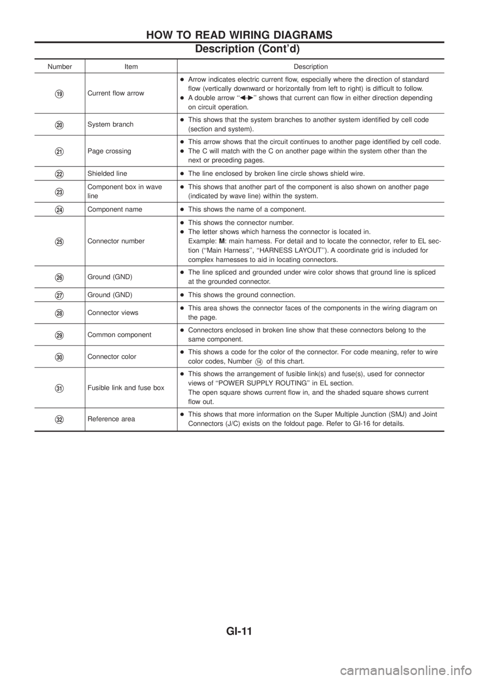
Number Item Description
V19Current ¯ow arrow+Arrow indicates electric current ¯ow, especially where the direction of standard
¯ow (vertically downward or horizontally from left to right) is difficult to follow.
+A double arrow ``bÐ
c'' shows that current can ¯ow in either direction depending
on circuit operation.
V20System branch+This shows that the system branches to another system identi®ed by cell code
(section and system).
V21Page crossing+This arrow shows that the circuit continues to another page identi®ed by cell code.
+The C will match with the C on another page within the system other than the
next or preceding pages.
V22Shielded line+The line enclosed by broken line circle shows shield wire.
V23Component box in wave
line+This shows that another part of the component is also shown on another page
(indicated by wave line) within the system.
V24Component name+This shows the name of a component.
V25Connector number+This shows the connector number.
+The letter shows which harness the connector is located in.
Example:M: main harness. For detail and to locate the connector, refer to EL sec-
tion (``Main Harness'', ``HARNESS LAYOUT''). A coordinate grid is included for
complex harnesses to aid in locating connectors.
V26Ground (GND)+The line spliced and grounded under wire color shows that ground line is spliced
at the grounded connector.
V27Ground (GND)+This shows the ground connection.
V28Connector views+This area shows the connector faces of the components in the wiring diagram on
the page.
V29Common component+Connectors enclosed in broken line show that these connectors belong to the
same component.
V30Connector color+This shows a code for the color of the connector. For code meaning, refer to wire
color codes, NumberV14of this chart.
V31Fusible link and fuse box+This shows the arrangement of fusible link(s) and fuse(s), used for connector
views of ``POWER SUPPLY ROUTING'' in EL section.
The open square shows current ¯ow in, and the shaded square shows current
¯ow out.
V32Reference area+This shows that more information on the Super Multiple Junction (SMJ) and Joint
Connectors (J/C) exists on the foldout page. Refer to GI-16 for details.
HOW TO READ WIRING DIAGRAMS
Description (Cont'd)
GI-11
Page 847 of 1226
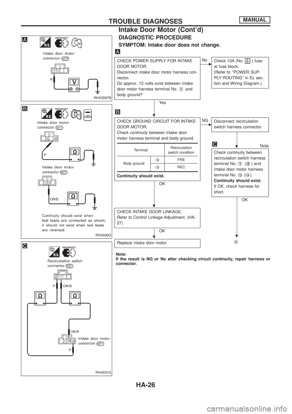
DIAGNOSTIC PROCEDURE
SYMPTOM: Intake door does not change.
CHECK POWER SUPPLY FOR INTAKE
DOOR MOTOR.
Disconnect intake door motor harness con-
nector.
Do approx. 12 volts exist between intake
door motor harness terminal No.j
1and
body ground?
Ye s
cNo
Check 10A (No.) fuse
at fuse block.
(Refer to ``POWER SUP-
PLY ROUTING'' in EL sec-
tion and Wiring Diagram.)
CHECK GROUND CIRCUIT FOR INTAKE
DOOR MOTOR.
Check continuity between intake door
motor harness terminal and body ground.
Continuity should exist.
OK
cNG
Disconnect recirculation
switch harness connector.
Note
Check continuity between
recirculation switch harness
terminal No.j
1(j2) and
intake door motor harness
terminal No.j
13(j14).
Continuity should exist.
If OK, check harness for
short.
OK
CHECK INTAKE DOOR LINKAGE.
Refer to Control Linkage Adjustment. (HA-
27)
OK
Replace intake door motor.
jA
TerminalRecirculation
switch condition
Body groundj
14FRE
j
13REC
Note:
If the result is NG or No after checking circuit continuity, repair harness or
connector.
RHA350FB
RHA590G
RHA591G
.
.
.
..
TROUBLE DIAGNOSESMANUAL
Intake Door Motor (Cont'd)
HA-26
Page 850 of 1226
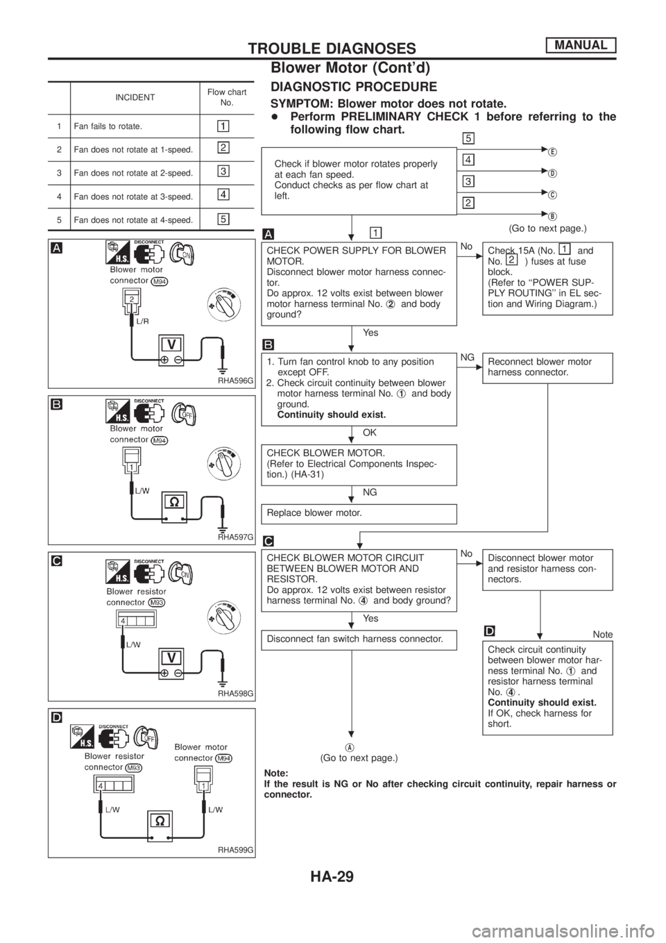
INCIDENTFlow chart
No.
1 Fan fails to rotate.
2 Fan does not rotate at 1-speed.
3 Fan does not rotate at 2-speed.
4 Fan does not rotate at 3-speed.
5 Fan does not rotate at 4-speed.
DIAGNOSTIC PROCEDURE
SYMPTOM: Blower motor does not rotate.
+Perform PRELIMINARY CHECK 1 before referring to the
following ¯ow chart.
Check if blower motor rotates properly
at each fan speed.
Conduct checks as per ¯ow chart at
left.
cjE
cjD
cjC
cjB
(Go to next page.)
CHECK POWER SUPPLY FOR BLOWER
MOTOR.
Disconnect blower motor harness connec-
tor.
Do approx. 12 volts exist between blower
motor harness terminal No.j
2and body
ground?
Ye s
cNo
Check 15A (No.and
No.) fuses at fuse
block.
(Refer to ``POWER SUP-
PLY ROUTING'' in EL sec-
tion and Wiring Diagram.)
1. Turn fan control knob to any position
except OFF.
2. Check circuit continuity between blower
motor harness terminal No.j
1and body
ground.
Continuity should exist.
OK
cNG
Reconnect blower motor
harness connector.
CHECK BLOWER MOTOR.
(Refer to Electrical Components Inspec-
tion.) (HA-31)
NG
Replace blower motor.
.
CHECK BLOWER MOTOR CIRCUIT
BETWEEN BLOWER MOTOR AND
RESISTOR.
Do approx. 12 volts exist between resistor
harness terminal No.j
4and body ground?
Ye s
cNo
Disconnect blower motor
and resistor harness con-
nectors.
Disconnect fan switch harness connector.Note
Check circuit continuity
between blower motor har-
ness terminal No.j
1and
resistor harness terminal
No.j
4.
Continuity should exist.
If OK, check harness for
short.
jA(Go to next page.)
Note:
If the result is NG or No after checking circuit continuity, repair harness or
connector.
RHA596G
RHA597G
RHA598G
RHA599G
.
.
.
.
..
.
TROUBLE DIAGNOSESMANUAL
Blower Motor (Cont'd)
HA-29
Page 865 of 1226
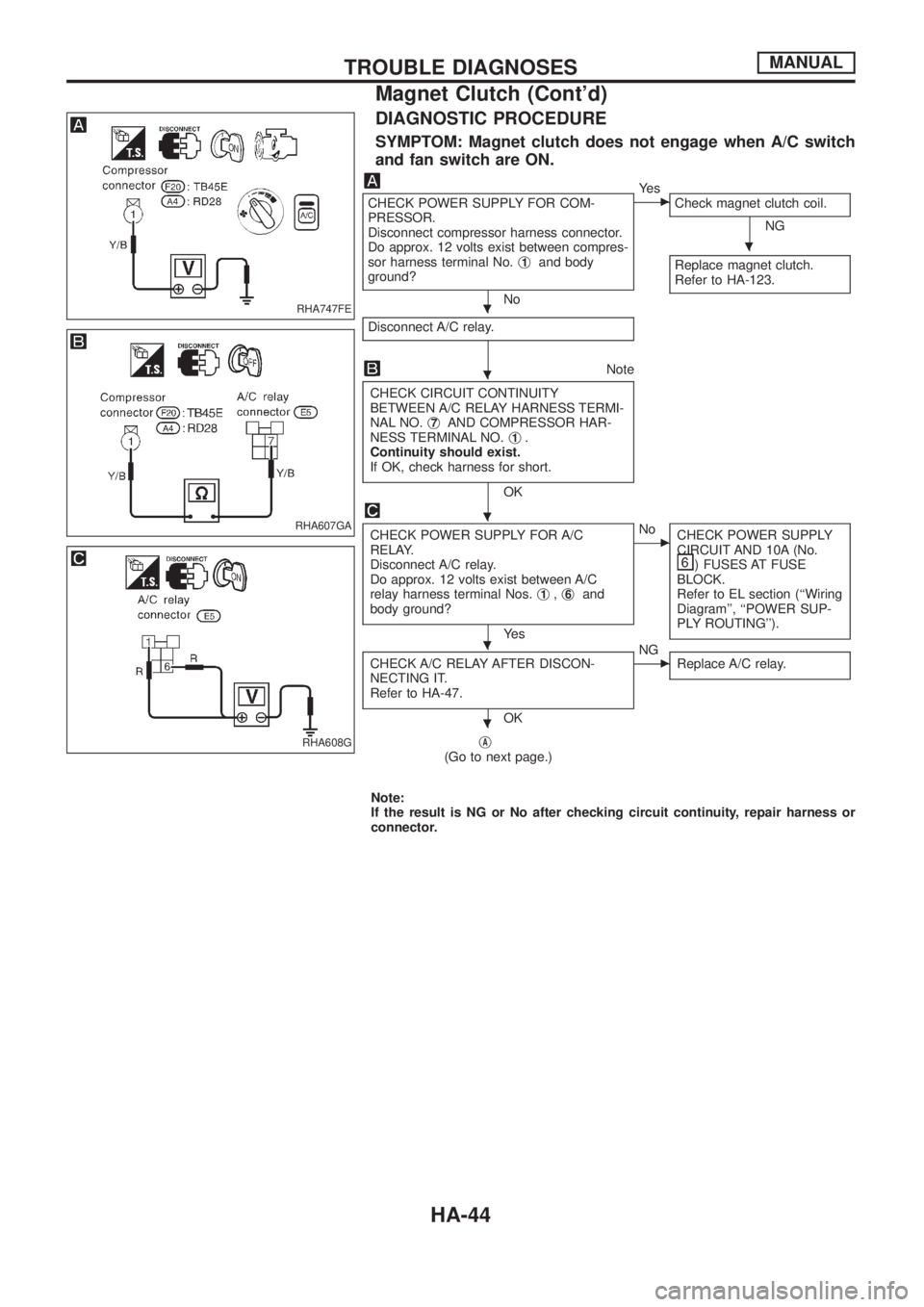
DIAGNOSTIC PROCEDURE
SYMPTOM: Magnet clutch does not engage when A/C switch
and fan switch are ON.
CHECK POWER SUPPLY FOR COM-
PRESSOR.
Disconnect compressor harness connector.
Do approx. 12 volts exist between compres-
sor harness terminal No.j
1and body
ground?
No
cYe s
Check magnet clutch coil.
NG
Replace magnet clutch.
Refer to HA-123.
Disconnect A/C relay.
Note
CHECK CIRCUIT CONTINUITY
BETWEEN A/C RELAY HARNESS TERMI-
NAL NO.j
7AND COMPRESSOR HAR-
NESS TERMINAL NO.j1.
Continuity should exist.
If OK, check harness for short.
OK
CHECK POWER SUPPLY FOR A/C
RELAY.
Disconnect A/C relay.
Do approx. 12 volts exist between A/C
relay harness terminal Nos.j
1,j6and
body ground?
Ye s
cNo
CHECK POWER SUPPLY
CIRCUIT AND 10A (No.
) FUSES AT FUSE
BLOCK.
Refer to EL section (``Wiring
Diagram'', ``POWER SUP-
PLY ROUTING'').
CHECK A/C RELAY AFTER DISCON-
NECTING IT.
Refer to HA-47.
OK
cNG
Replace A/C relay.
jA(Go to next page.)
Note:
If the result is NG or No after checking circuit continuity, repair harness or
connector.
RHA747FE
RHA607GA
RHA608G
.
.
.
.
.
.
TROUBLE DIAGNOSESMANUAL
Magnet Clutch (Cont'd)
HA-44
Page 867 of 1226
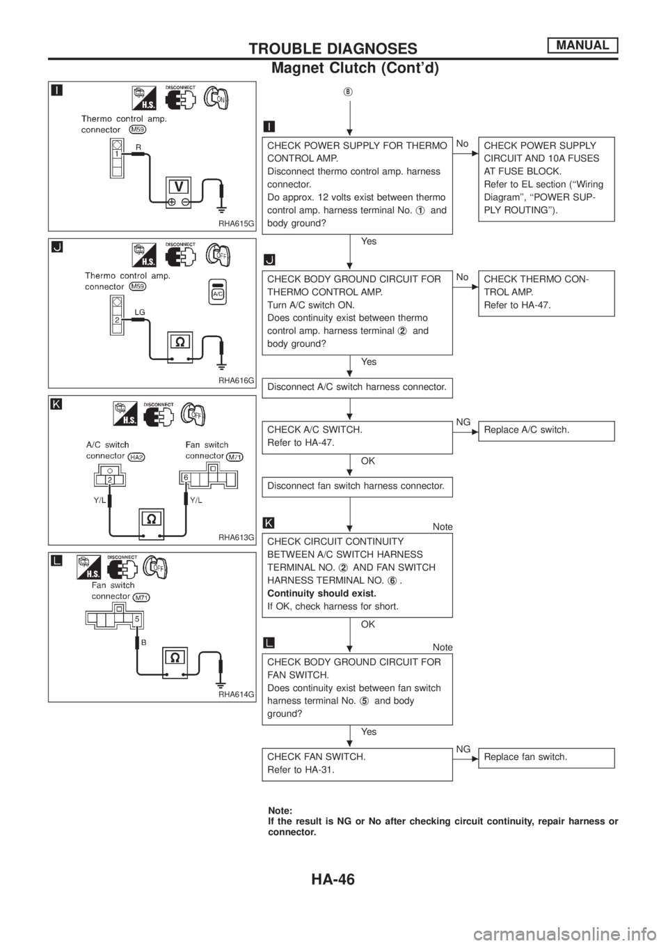
jB
CHECK POWER SUPPLY FOR THERMO
CONTROL AMP.
Disconnect thermo control amp. harness
connector.
Do approx. 12 volts exist between thermo
control amp. harness terminal No.j
1and
body ground?
Ye s
cNo
CHECK POWER SUPPLY
CIRCUIT AND 10A FUSES
AT FUSE BLOCK.
Refer to EL section (``Wiring
Diagram'', ``POWER SUP-
PLY ROUTING'').
CHECK BODY GROUND CIRCUIT FOR
THERMO CONTROL AMP.
Turn A/C switch ON.
Does continuity exist between thermo
control amp. harness terminalj
2and
body ground?
Ye s
cNo
CHECK THERMO CON-
TROL AMP.
Refer to HA-47.
Disconnect A/C switch harness connector.
CHECK A/C SWITCH.
Refer to HA-47.
OK
cNG
Replace A/C switch.
Disconnect fan switch harness connector.
Note
CHECK CIRCUIT CONTINUITY
BETWEEN A/C SWITCH HARNESS
TERMINAL NO.j
2AND FAN SWITCH
HARNESS TERMINAL NO.j
6.
Continuity should exist.
If OK, check harness for short.
OK
Note
CHECK BODY GROUND CIRCUIT FOR
FAN SWITCH.
Does continuity exist between fan switch
harness terminal No.j
5and body
ground?
Ye s
CHECK FAN SWITCH.
Refer to HA-31.
cNG
Replace fan switch.
Note:
If the result is NG or No after checking circuit continuity, repair harness or
connector.
RHA615G
RHA616G
RHA613G
RHA614G
.
.
.
.
.
.
.
.
TROUBLE DIAGNOSESMANUAL
Magnet Clutch (Cont'd)
HA-46