2006 NISSAN PATROL Electrical
[x] Cancel search: ElectricalPage 1 of 1226

Edition: February 1998
Release: February 1998 (01)
Publication No.: SM8E-0Y61E0E
Reference No.: 7711346063GENERAL INFORMATIONGI
MAINTENANCEMA
ENGINE MECHANICALEM
ENGINE LUBRICATION &
COOLING SYSTEMSLC
ENGINE CONTROL SYSTEMEC
ACCELERATOR CONTROL,
FUEL & EXHAUST SYSTEMFE
CLUTCHCL
MANUAL TRANSMISSIONMT
AUTOMATIC TRANSMISSIONAT
TRANSFERTF
PROPELLER SHAFT &
DIFFERENTIAL CARRIERPD
FRONT AXLE & FRONT SUSPENSIONFA
REAR AXLE & REAR SUSPENSIONRA
BRAKE SYSTEMBR
STEERING SYSTEMST
RESTRAINT SYSTEMRS
BODY & TRIMBT
HEATER & AIR CONDITIONERHA
ELECTRICAL SYSTEMEL
ALPHABETICAL INDEXIDX
PATROL GR
MODEL Y61 SERIES
NISSAN EUROPE S.A.S.
1998 NISSAN EUROPE S.A.S.
Produced in The Netherlands
Not to be reproduced in whole or in part
without the prior written permission of
Nissan Europe S.A.S., Paris, France.
QUICK REFERENCE INDEX
Page 4 of 1226
Ground Circuit Check ................................................56
TROUBLE DIAGNOSES FOR SELF-DIAGNOSTIC
ITEMS ........................................................................\
.....57
Diagnostic Procedure 1 (Wheel sensor or rotor) ......57
Diagnostic Procedure 2 (ABS actuator solenoid
valve and solenoid valve relay) .................................59
Diagnostic Procedure 3 (Motor relay or motor).........61
Diagnostic Procedure 4 (Low voltage) ......................63
Diagnostic Procedure 5 (G sensor) ...........................64
Diagnostic Procedure 6 (Control unit) .......................65
TROUBLE DIAGNOSES FOR SYMPTOMS .................66
Diagnostic Procedure 7 (ABS works frequently.) ......66
Diagnostic Procedure 8 (Unexpected pedal
action) ........................................................................\
67 Diagnostic Procedure 9 (Long stopping distance) ....67
Diagnostic Procedure 10 (ABS does not work.) .......68
Diagnostic Procedure 11 (Pedal vibration and
noise) ........................................................................\
.68
Diagnostic Procedure 12 (Warning lamp does
not come on when ignition switch is turned ON.) .....69
Diagnostic Procedure 13 (Warning lamp stays on
when ignition switch is turned ON.)...........................71
SERVICE DATA AND SPECIFICATIONS (SDS) ..........72
General Speci®cations ...............................................72
Inspection and Adjustment ........................................73
When you read wiring diagrams:
+ Read GI section, ``HOW TO READ WIRING DIAGRAMS''.
+ See EL section, ``POWER SUPPLY ROUTING'' for power distribution circuit.
When you perform trouble diagnoses, read GI section, ``HOW TO FOLLOW FLOW CHART
IN TROUBLE DIAGNOSES'' and ``HOW TO PERFORM EFFICIENT DIAGNOSIS FOR AN
ELECTRICAL INCIDENT''.
Page 5 of 1226
Supplemental Restraint System (SRS) ``AIR
BAG'' and ``SEAT BELT PRE-TENSIONER''
The Supplemental Restraint System such as ``AIR BAG'' and ``SEAT BELT PRE-TENSIONER'' used along with
a seat belt, helps to reduce the risk or severity of injury to the driver and front passenger in a frontal collision.
The SRS system composition which is available to NISSAN MODEL Y61 is as follows (The composition var-
ies according to the destination.):
Driver air bag module (located in the center of the steering wheel), front passenger air bag module (located
on the instrument panel on passenger side), seat belt pre-tensioner, a diagnosis sensor unit, warning lamp,
wiring harness and spiral cable.
Information necessary to service the system safely is included in theRS sectionof this Service Manual.
WARNING:
+ To avoid rendering the SRS inoperative, which could increase the risk of personal injury or death
in the event of a collision which would result in air bag in¯ation, all maintenance must be performed
by an authorized NISSAN dealer.
+ Improper maintenance, including incorrect removal and installation of the SRS, can lead to per-
sonal injury caused by unintentional activation of the system. For removal of Spiral Cable and Air
Bag Module, see the RS section.
+ Do not use electrical test equipment on any circuit related to the SRS unless instructed to in this
Service Manual. Spiral Cable and wiring harnesses covered with yellow insulation either just before
the harness connectors or for the complete harness are related to the SRS.
Precautions for Brake System
+Use brake ¯uid ``DOT 3''.
+ Never reuse drained brake ¯uid.
+ Be careful not to splash brake ¯uid on painted areas; it
may cause paint damage. If brake ¯uid is splashed on
painted areas, wash it away with water immediately.
+ To clean master cylinder parts, disc brake caliper parts or
wheel cylinder parts, use clean brake ¯uid.
+ Never use mineral oils such as gasoline or kerosene. They
will ruin rubber parts of hydraulic system.
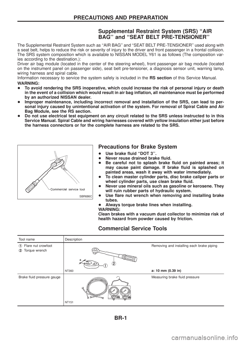
+ Use ¯are nut wrench when removing and installing brake
tubes.
+ Always torque brake lines when installing.
WARNING:
Clean brakes with a vacuum dust collector to minimize risk of
health hazard from powder caused by friction.
Commercial Service Tools
Tool name Description
j
1Flare nut crowfoot
j
2Torque wrench
NT360
Removing and installing each brake piping
a: 10 mm (0.39 in)
Brake ¯uid pressure gauge
NT151
Measuring brake ¯uid pressure
SBR686C
PRECAUTIONS AND PREPARATION
BR-1
Page 38 of 1226
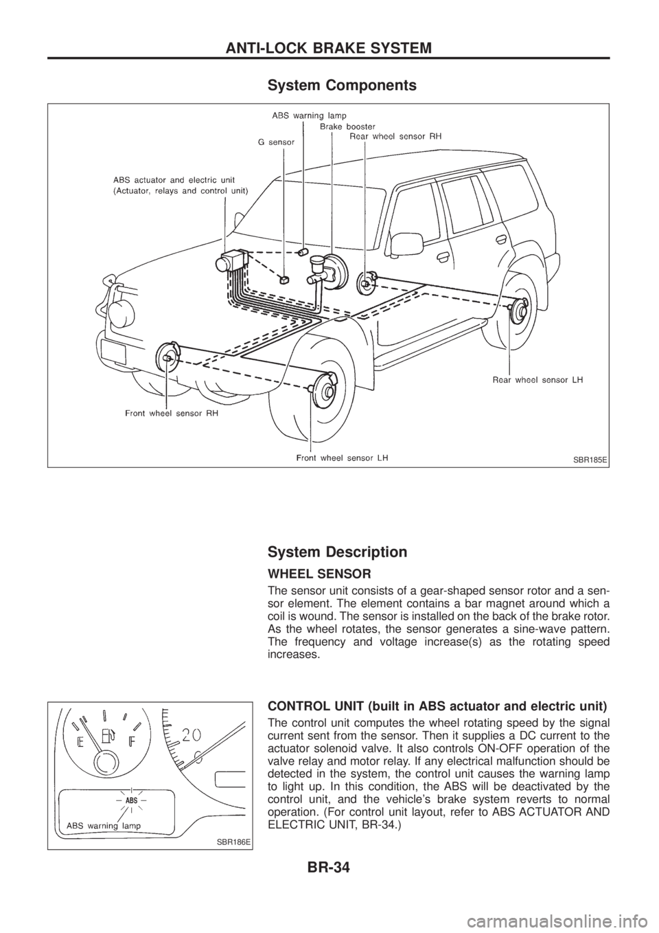
System Components
System Description
WHEEL SENSOR
The sensor unit consists of a gear-shaped sensor rotor and a sen-
sor element. The element contains a bar magnet around which a
coil is wound. The sensor is installed on the back of the brake rotor.
As the wheel rotates, the sensor generates a sine-wave pattern.
The frequency and voltage increase(s) as the rotating speed
increases.
CONTROL UNIT (built in ABS actuator and electric unit)
The control unit computes the wheel rotating speed by the signal
current sent from the sensor. Then it supplies a DC current to the
actuator solenoid valve. It also controls ON-OFF operation of the
valve relay and motor relay. If any electrical malfunction should be
detected in the system, the control unit causes the warning lamp
to light up. In this condition, the ABS will be deactivated by the
control unit, and the vehicle's brake system reverts to normal
operation. (For control unit layout, refer to ABS ACTUATOR AND
ELECTRIC UNIT, BR-34.)
SBR185E
SBR186E
ANTI-LOCK BRAKE SYSTEM
BR-34
Page 61 of 1226
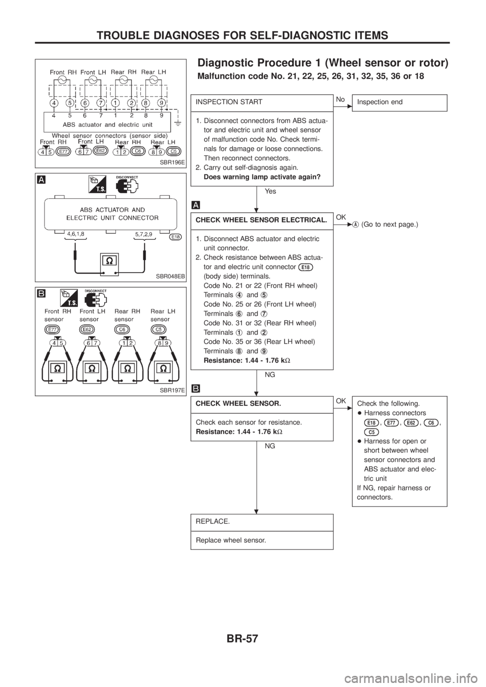
Diagnostic Procedure 1 (Wheel sensor or rotor)
Malfunction code No. 21, 22, 25, 26, 31, 32, 35, 36 or 18
INSPECTION START
- ---------------------------------------------------------------------------------------------------------------------------------------------------------------------------------------------------------------------------------------------------------------------------------------------------------------
1. Disconnect connectors from ABS actua- tor and electric unit and wheel sensor
of malfunction code No. Check termi-
nals for damage or loose connections.
Then reconnect connectors.
2. Carry out self-diagnosis again. Does warning lamp activate again?
Ye s
cNo Inspection end
CHECK WHEEL SENSOR ELECTRICAL.
- ---------------------------------------------------------------------------------------------------------------------------------------------------------------------------------------------------------------------------------------------------------------------------------------------------------------
1. Disconnect ABS actuator and electric unit connector.
2. Check resistance between ABS actua- tor and electric unit connector
E18
(body side) terminals.
Code No. 21 or 22 (Front RH wheel)
Terminals j
4andj5
Code No. 25 or 26 (Front LH wheel)
Terminals j
6andj7
Code No. 31 or 32 (Rear RH wheel)
Terminals j
1andj2
Code No. 35 or 36 (Rear LH wheel)
Terminals j
8andj9
Resistance: 1.44 - 1.76 k
W
NG
cOK
jA(Go to next page.)
CHECK WHEEL SENSOR.
- ---------------------------------------------------------------------------------------------------------------------------------------------------------------------------------------------------------------------------------------------------------------------------------------------------------------
Check each sensor for resistance.
Resistance: 1.44 - 1.76 k W
NG
cOK
Check the following.
+Harness connectors
E18,E77,E62,C6,
C5
+Harness for open or
short between wheel
sensor connectors and
ABS actuator and elec-
tric unit
If NG, repair harness or
connectors.
REPLACE.
- ---------------------------------------------------------------------------------------------------------------------------------------------------------------------------------------------------------------------------------------------------------------------------------------------------------------
Replace wheel sensor.
SBR196E
SBR048EB
SBR197E
.
.
.
TROUBLE DIAGNOSES FOR SELF-DIAGNOSTIC ITEMS
BR-57
Page 68 of 1226
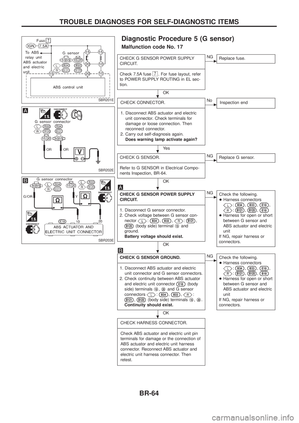
Diagnostic Procedure 5 (G sensor)
Malfunction code No. 17
CHECK G SENSOR POWER SUPPLY
CIRCUIT.
- ---------------------------------------------------------------------------------------------------------------------------------------------------------------------------------------------------------------------------------------------------------------------------------------------------------------
Check 7.5A fuse
7. For fuse layout, refer
to POWER SUPPLY ROUTING in EL sec-
tion.
OK
cNG Replace fuse.
CHECK CONNECTOR.
- ---------------------------------------------------------------------------------------------------------------------------------------------------------------------------------------------------------------------------------------------------------------------------------------------------------------
1. Disconnect ABS actuator and electric unit connector. Check terminals for
damage or loose connection. Then
reconnect connector.
2. Carry out self-diagnosis again. Does warning lamp activate again?
Ye s
cNo Inspection end
CHECK G SENSOR.
- ---------------------------------------------------------------------------------------------------------------------------------------------------------------------------------------------------------------------------------------------------------------------------------------------------------------
Refer to G SENSOR in Electrical Compo-
nents Inspection, BR-64.
OK
cNG Replace G sensor.
CHECK G SENSOR POWER SUPPLY
CIRCUIT.
- ---------------------------------------------------------------------------------------------------------------------------------------------------------------------------------------------------------------------------------------------------------------------------------------------------------------
1. Disconnect G sensor connector.
2. Check voltage between G sensor con- nector
:B34,B33,:B121,
B120(body side) terminal j15and
ground.
Battery voltage should exist.
OK
cNG Check the following.
+Harness connectors
:B34,B33,E18,
:B121,B120,E18
+Harness for open or short
between G sensor and
ABS actuator and electric
unit
If NG, repair harness or
connectors.
CHECK G SENSOR GROUND.
- ---------------------------------------------------------------------------------------------------------------------------------------------------------------------------------------------------------------------------------------------------------------------------------------------------------------
1. Disconnect ABS actuator and electric unit connector and G sensor connectors.
2. Check continuity between ABS actuator and electric unit connector
E18(body
side) terminals j
10,j20and G sensor
connectors
:B34,B33,:
B121,B120(body side) terminals j10,j20.
Continuity should exist.
OK
cNG Check the following.
+Harness connectors
:B34,B33,E18,
:B121,B120,B18
+Harness for open or short
between G sensor and
ABS actuator and electric
unit
If NG, repair harness or
connectors.
CHECK HARNESS CONNECTOR.
- ---------------------------------------------------------------------------------------------------------------------------------------------------------------------------------------------------------------------------------------------------------------------------------------------------------------
Check ABS actuator and electric unit pin
terminals for damage or the connection of
ABS actuator and electric unit harness
connector. Reconnect ABS actuator and
electric unit harness connector. Then
retest.
SBR201E
SBR202E
SBR203E
.
.
.
.
.
TROUBLE DIAGNOSES FOR SELF-DIAGNOSTIC ITEMS
BR-64
Page 69 of 1226
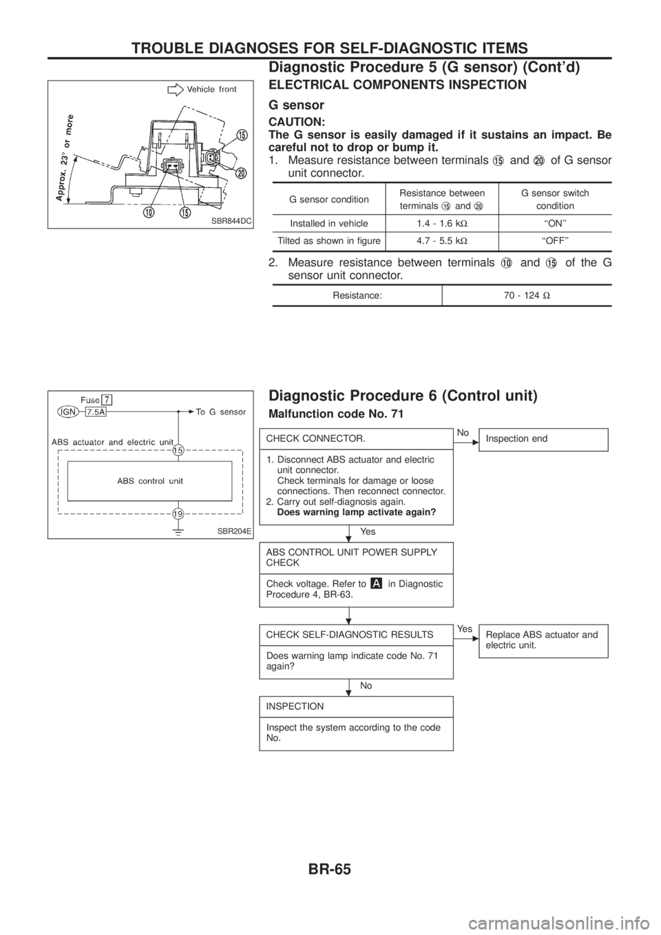
ELECTRICAL COMPONENTS INSPECTION
G sensor
CAUTION:
The G sensor is easily damaged if it sustains an impact. Be
careful not to drop or bump it.
1. Measure resistance between terminalsj
15andj20of G sensor
unit connector.
G sensor condition Resistance between
terminals j15andj20
G sensor switch
condition
Installed in vehicle 1.4 - 1.6 k W``ON''
Tilted as shown in ®gure 4.7 - 5.5 k W``OFF''
2. Measure resistance between terminals j10andj15of the G
sensor unit connector.
Resistance: 70 - 124 W
Diagnostic Procedure 6 (Control unit)
Malfunction code No. 71
CHECK CONNECTOR.
- ---------------------------------------------------------------------------------------------------------------------------------------------------------------------------------------------------------------------------------------------------------------------------------------------------------------
1. Disconnect ABS actuator and electric unit connector.
Check terminals for damage or loose
connections. Then reconnect connector.
2. Carry out self-diagnosis again. Does warning lamp activate again?
Ye s
cNo Inspection end
ABS CONTROL UNIT POWER SUPPLY
CHECK
- ---------------------------------------------------------------------------------------------------------------------------------------------------------------------------------------------------------------------------------------------------------------------------------------------------------------
Check voltage. Refer to
in Diagnostic
Procedure 4, BR-63.
CHECK SELF-DIAGNOSTIC RESULTS
- ---------------------------------------------------------------------------------------------------------------------------------------------------------------------------------------------------------------------------------------------------------------------------------------------------------------
Does warning lamp indicate code No. 71
again?
No
cYe s Replace ABS actuator and
electric unit.
INSPECTION
- ---------------------------------------------------------------------------------------------------------------------------------------------------------------------------------------------------------------------------------------------------------------------------------------------------------------
Inspect the system according to the code
No.
SBR844DC
SBR204E.
.
.
TROUBLE DIAGNOSES FOR SELF-DIAGNOSTIC ITEMS
Diagnostic Procedure 5 (G sensor) (Cont'd)
BR-65
Page 72 of 1226
Diagnostic Procedure 10 (ABS does not work.)
CHECK WARNING LAMP ACTIVATE.
- ---------------------------------------------------------------------------------------------------------------------------------------------------------------------------------------------------------------------------------------------------------------------------------------------------------------
Does the ABS warning lamp activate?
No
cYe s Carry out self-diagnosis.
Refer to BR-47, 51.
Go toin Diagnostic Procedure 8,
BR-67.
Note: ABS does not work when vehicle speed is under 10 km/h (6 MPH).
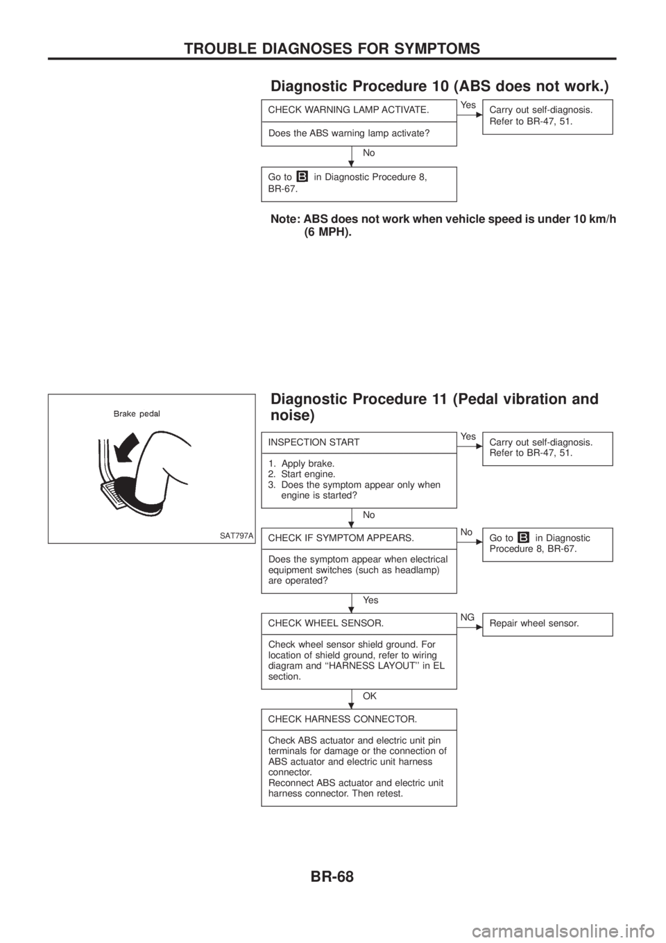
Diagnostic Procedure 11 (Pedal vibration and
noise)
INSPECTION START
- ---------------------------------------------------------------------------------------------------------------------------------------------------------------------------------------------------------------------------------------------------------------------------------------------------------------
1. Apply brake.
2. Start engine.
3. Does the symptom appear only when engine is started?
No
cYe s Carry out self-diagnosis.
Refer to BR-47, 51.
CHECK IF SYMPTOM APPEARS.
- ---------------------------------------------------------------------------------------------------------------------------------------------------------------------------------------------------------------------------------------------------------------------------------------------------------------
Does the symptom appear when electrical
equipment switches (such as headlamp)
are operated?
Ye s
cNo Go toin Diagnostic
Procedure 8, BR-67.
CHECK WHEEL SENSOR.
- ---------------------------------------------------------------------------------------------------------------------------------------------------------------------------------------------------------------------------------------------------------------------------------------------------------------
Check wheel sensor shield ground. For
location of shield ground, refer to wiring
diagram and ``HARNESS LAYOUT'' in EL
section.
OK
cNG Repair wheel sensor.
CHECK HARNESS CONNECTOR.
- ---------------------------------------------------------------------------------------------------------------------------------------------------------------------------------------------------------------------------------------------------------------------------------------------------------------
Check ABS actuator and electric unit pin
terminals for damage or the connection of
ABS actuator and electric unit harness
connector.
Reconnect ABS actuator and electric unit
harness connector. Then retest.
SAT797A
.
.
.
.
TROUBLE DIAGNOSES FOR SYMPTOMS
BR-68