2006 NISSAN PATROL brake rotor
[x] Cancel search: brake rotorPage 3 of 1226
BRAKE SYSTEM
SECTION
BR
CONTENTS
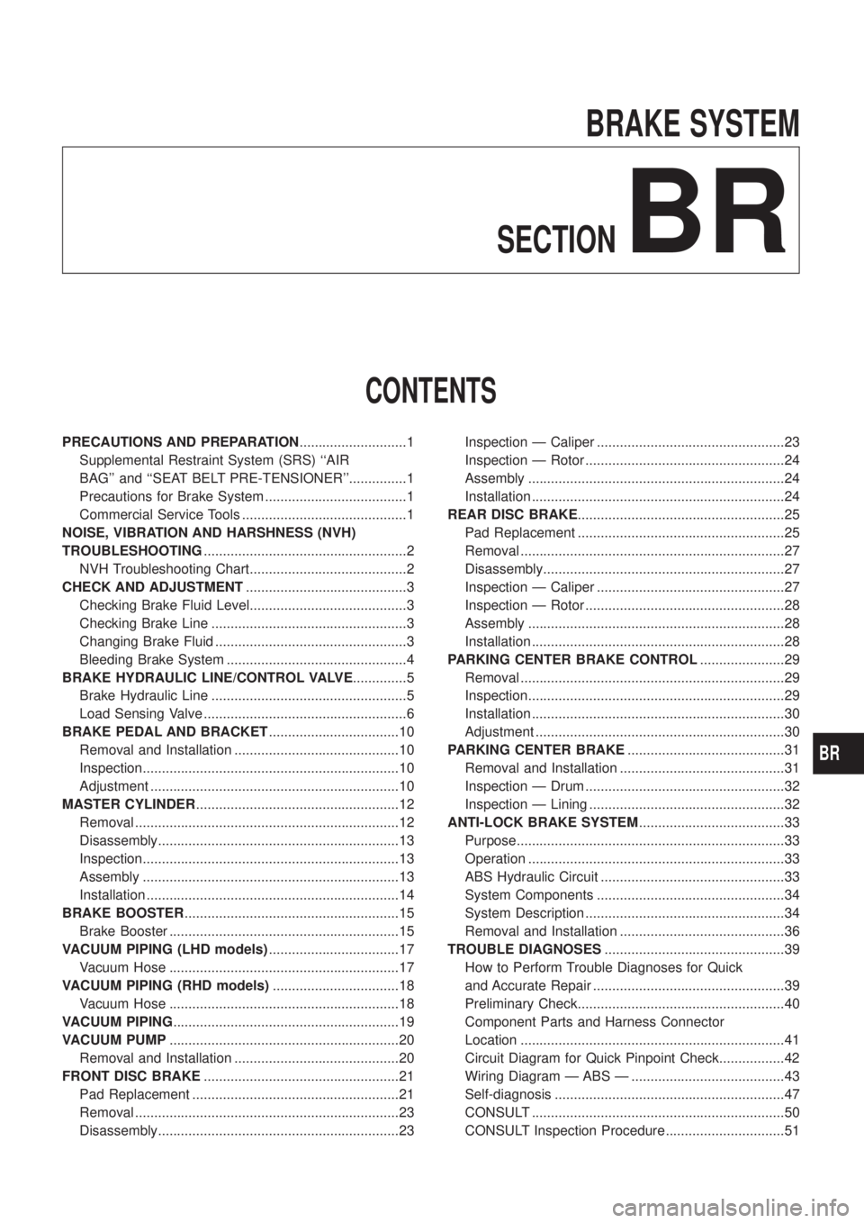
PRECAUTIONS AND PREPARATION ............................1
Supplemental Restraint System (SRS) ``AIR
BAG'' and ``SEAT BELT PRE-TENSIONER''...............1
Precautions for Brake System .....................................1
Commercial Service Tools ...........................................1
NOISE, VIBRATION AND HARSHNESS (NVH)
TROUBLESHOOTING .....................................................2
NVH Troubleshooting Chart.........................................2
CHECK AND ADJUSTMENT ..........................................3
Checking Brake Fluid Level.........................................3
Checking Brake Line ...................................................3
Changing Brake Fluid ..................................................3
Bleeding Brake System ...............................................4
BRAKE HYDRAULIC LINE/CONTROL VALVE ..............5
Brake Hydraulic Line ...................................................5
Load Sensing Valve .....................................................6
BRAKE PEDAL AND BRACKET ..................................10
Removal and Installation ...........................................10
Inspection...................................................................10
Adjustment .................................................................10
MASTER CYLINDER .....................................................12
Removal .....................................................................12
Disassembly...............................................................13
Inspection...................................................................13
Assembly ...................................................................13
Installation ..................................................................14
BRAKE BOOSTER ........................................................15
Brake Booster ............................................................15
VACUUM PIPING (LHD models) ..................................17
Vacuum Hose ............................................................17
VACUUM PIPING (RHD models) .................................18
Vacuum Hose ............................................................18
VACUUM PIPING ...........................................................19
VACUUM PUMP ............................................................20
Removal and Installation ...........................................20
FRONT DISC BRAKE ...................................................21
Pad Replacement ......................................................21
Removal .....................................................................23
Disassembly...............................................................23 Inspection Ð Caliper .................................................23
Inspection Ð Rotor ....................................................24
Assembly ...................................................................24
Installation ..................................................................24
REAR DISC BRAKE ......................................................25
Pad Replacement ......................................................25
Removal .....................................................................27
Disassembly...............................................................27
Inspection Ð Caliper .................................................27
Inspection Ð Rotor ....................................................28
Assembly ...................................................................28
Installation ..................................................................28
PARKING CENTER BRAKE CONTROL ......................29
Removal .....................................................................29
Inspection...................................................................29
Installation ..................................................................30
Adjustment .................................................................30
PARKING CENTER BRAKE .........................................31
Removal and Installation ...........................................31
Inspection Ð Drum ....................................................32
Inspection Ð Lining ...................................................32
ANTI-LOCK BRAKE SYSTEM ......................................33
Purpose......................................................................33
Operation ...................................................................33
ABS Hydraulic Circuit ................................................33
System Components .................................................34
System Description ....................................................34
Removal and Installation ...........................................36
TROUBLE DIAGNOSES ...............................................39
How to Perform Trouble Diagnoses for Quick
and Accurate Repair ..................................................39
Preliminary Check......................................................40
Component Parts and Harness Connector
Location .....................................................................41
Circuit Diagram for Quick Pinpoint Check.................42
Wiring Diagram Ð ABS Ð ........................................43
Self-diagnosis ............................................................47
CONSULT ..................................................................50
CONSULT Inspection Procedure...............................51
BR
Page 6 of 1226
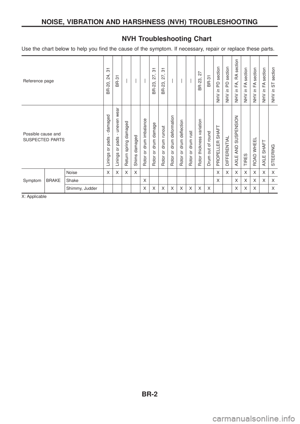
NVH Troubleshooting Chart
Use the chart below to help you ®nd the cause of the symptom. If necessary, repair or replace these parts.
Reference page
BR-20, 24, 31BR-31Ð
Ð
Ð
BR-23, 27, 31
BR-23, 27, 31 Ð
Ð
Ð
BR-23, 27 BR-31
NHV in PD section
NHV in PD section
NHV in FA, RA section
NHV in FA section
NHV in FA section
NHV in FA section
NHV in ST section
Possible cause and
SUSPECTED PARTS
Linings or pads - damaged
Linings or pads - uneven wear
Return spring damaged
Shims damaged
Rotor or drum imbalance
Rotor or drum damage
Rotor or drum runout
Rotor or drum deformation
Rotor or drum de¯ection
Rotor or drum rust
Rotor thickness variation
Drum out of round
PROPELLER SHAFT
DIFFERENTIAL
AXLE AND SUSPENSION
TIRES
ROAD WHEEL
AXLE SHAFT
STEERING
Symptom BRAKE Noise
XXXX XXXXXXX
Shake X X X X X X X
Shimmy, Judder X X XXXXXX XXX X
X: Applicable
NOISE, VIBRATION AND HARSHNESS (NVH) TROUBLESHOOTING
BR-2
Page 25 of 1226
Pad Replacement
WARNING:
Clean brakes with a vacuum dust collector to minimize the
hazard of airborne particles or other materials.
CAUTION:
+When cylinder body is removed, do not depress brake
pedal, or piston will pop out.
+ Be careful not to damage piston boot or get oil on rotor.
Always replace shims when replacing pads.
+ If shims are rusted or show peeling of the rubber coat,
replace them with new shims.
+ It is not necessary to remove connecting bolt except for
disassembly or replacement of caliper assembly. In this
case, suspend cylinder body with wire so as not to stretch
brake hose.
+ Carefully monitor brake ¯uid level because brake ¯uid will
return to reservoir when pushing back piston.
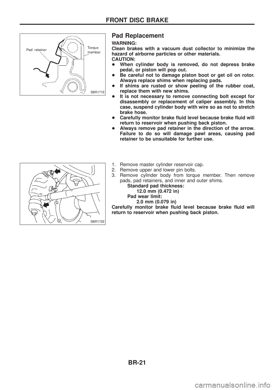
+ Always remove pad retainer in the direction of the arrow.
Failure to do so will damage pawl areas, causing pad
retainer to be unsuitable for further use.
1. Remove master cylinder reservoir cap.
2. Remove upper and lower pin bolts.
3. Remove cylinder body from torque member. Then remove pads, pad retainers, and inner and outer shims.Standard pad thickness: 12.0 mm (0.472 in)
Pad wear limit: 2.0 mm (0.079 in)
Carefully monitor brake ¯uid level because brake ¯uid will
return to reservoir when pushing back piston.
SBR171E
SBR172E
FRONT DISC BRAKE
BR-21
Page 28 of 1226
Inspection Ð Rotor
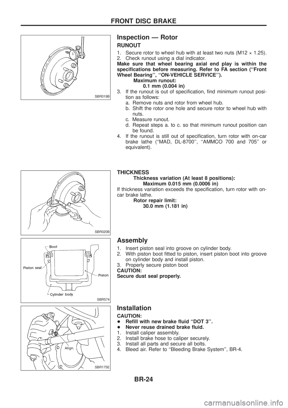
RUNOUT
1. Secure rotor to wheel hub with at least two nuts (M12 ý 1.25).
2. Check runout using a dial indicator.
Make sure that wheel bearing axial end play is within the
speci®cations before measuring. Refer to FA section (``Front
Wheel Bearing'', ``ON-VEHICLE SERVICE'').Maximum runout:0.1 mm (0.004 in)
3. If the runout is out of speci®cation, ®nd minimum runout posi- tion as follows:
a. Remove nuts and rotor from wheel hub.
b. Shift the rotor one hole and secure rotor to wheel hub withnuts.
c. Measure runout.
d. Repeat steps a. to c. so that minimum runout position can be found.
4. If the runout is still out of speci®cation, turn rotor with on-car brake lathe (``MAD, DL-8700'', ``AMMCO 700 and 705'' or
equivalent).
THICKNESS
Thickness variation (At least 8 positions): Maximum 0.015 mm (0.0006 in)
If thickness variation exceeds the speci®cation, turn rotor with on-
car brake lathe. Rotor repair limit:30.0 mm (1.181 in)
Assembly
1. Insert piston seal into groove on cylinder body.
2. With piston boot ®tted to piston, insert piston boot into grooveon cylinder body and install piston.
3. Properly secure piston boot
CAUTION:
Secure dust seal properly.
Installation
CAUTION:
+ Re®ll with new brake ¯uid ``DOT 3''.
+ Never reuse drained brake ¯uid.
1. Install caliper assembly.
2. Install brake hose to caliper securely.
3. Install all parts and secure all bolts.
4. Bleed air. Refer to ``Bleeding Brake System'', BR-4.
SBR019B
SBR020B
SBR574
SBR175E
FRONT DISC BRAKE
BR-24
Page 29 of 1226
Pad Replacement
WARNING:
Clean brakes with a vacuum dust collector to minimize the
hazard of airborne particles or other materials.
CAUTION:
+When cylinder body is open, do not depress brake pedal,
or piston will pop out.
+ Be careful not to damage piston boot or get oil on rotor.
Always replace shims when replacing pads.
+ If shims are rusted or show peeling of the rubber coat,
replace them with new shims.
+ It is not necessary to remove connecting bolt except for
disassembly or replacement of caliper assembly. In this
case, suspend cylinder body with wire so as not to stretch
brake hose.
+ Carefully monitor brake ¯uid level because brake ¯uid will
return to reservoir when pushing back piston.
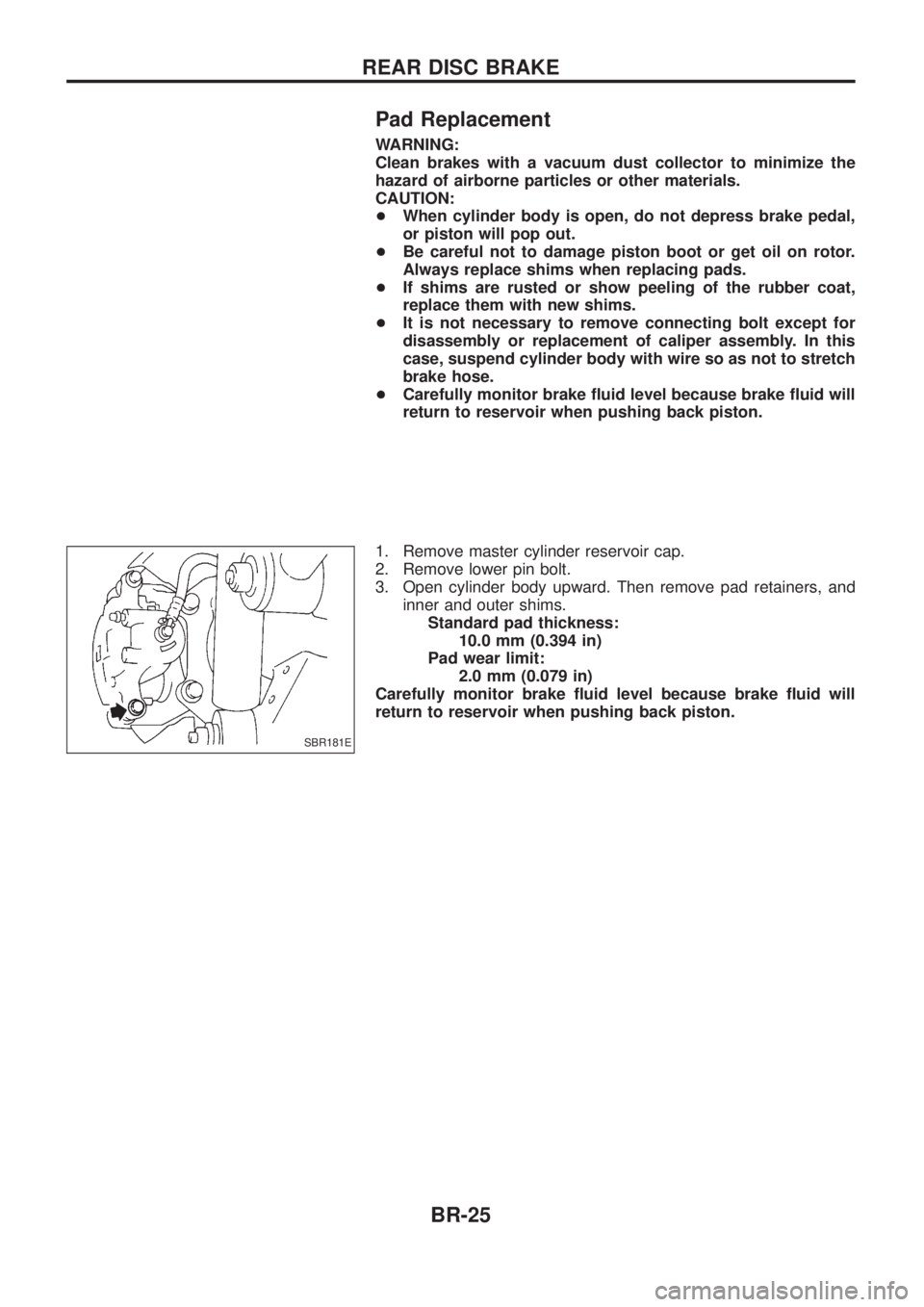
1. Remove master cylinder reservoir cap.
2. Remove lower pin bolt.
3. Open cylinder body upward. Then remove pad retainers, and inner and outer shims.Standard pad thickness: 10.0 mm (0.394 in)
Pad wear limit: 2.0 mm (0.079 in)
Carefully monitor brake ¯uid level because brake ¯uid will
return to reservoir when pushing back piston.
SBR181E
REAR DISC BRAKE
BR-25
Page 32 of 1226
Inspection Ð Rotor
RUNOUT
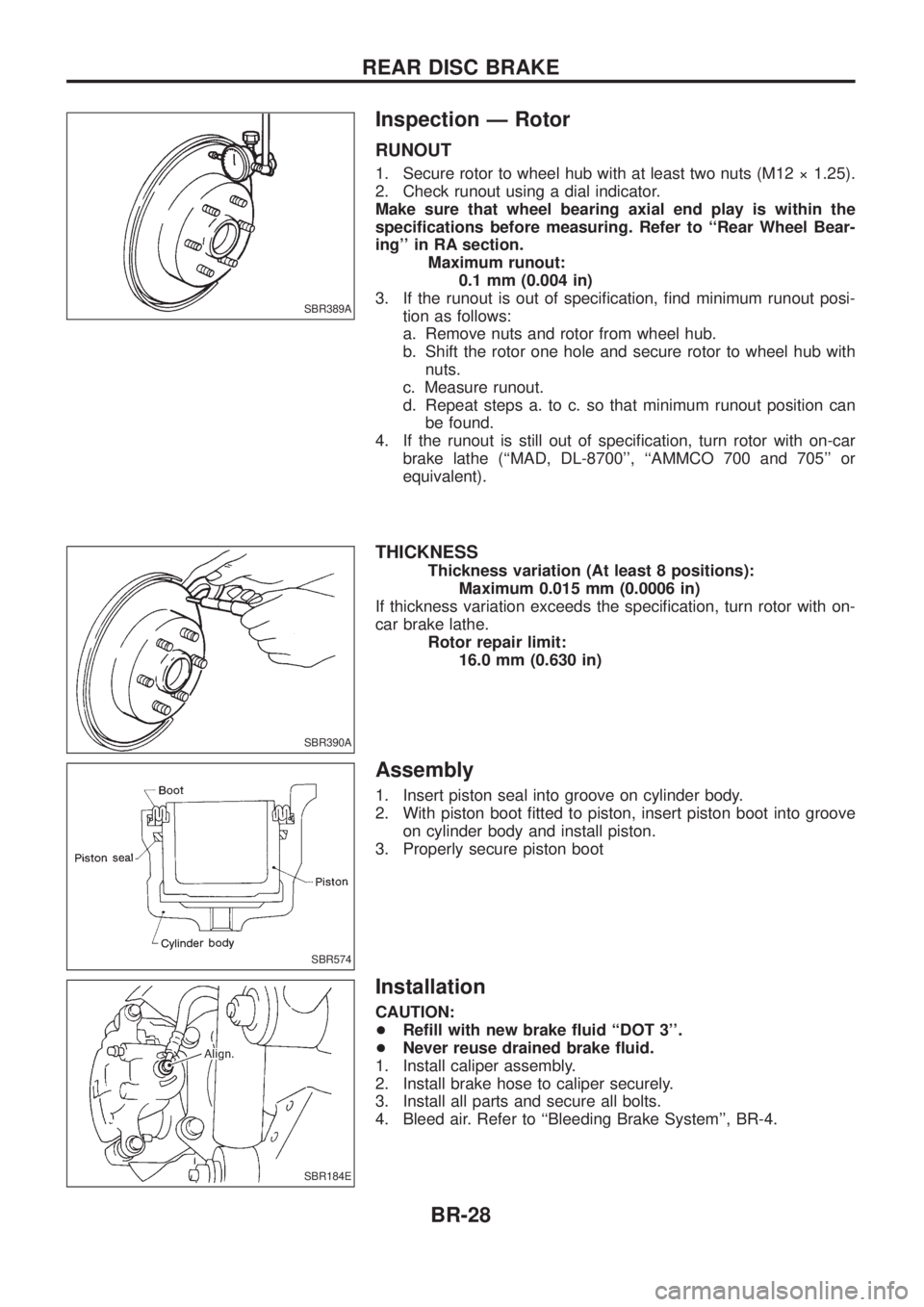
1. Secure rotor to wheel hub with at least two nuts (M12 ý 1.25).
2. Check runout using a dial indicator.
Make sure that wheel bearing axial end play is within the
speci®cations before measuring. Refer to ``Rear Wheel Bear-
ing'' in RA section.Maximum runout:0.1 mm (0.004 in)
3. If the runout is out of speci®cation, ®nd minimum runout posi- tion as follows:
a. Remove nuts and rotor from wheel hub.
b. Shift the rotor one hole and secure rotor to wheel hub withnuts.
c. Measure runout.
d. Repeat steps a. to c. so that minimum runout position can be found.
4. If the runout is still out of speci®cation, turn rotor with on-car brake lathe (``MAD, DL-8700'', ``AMMCO 700 and 705'' or
equivalent).
THICKNESS
Thickness variation (At least 8 positions): Maximum 0.015 mm (0.0006 in)
If thickness variation exceeds the speci®cation, turn rotor with on-
car brake lathe. Rotor repair limit:16.0 mm (0.630 in)
Assembly
1. Insert piston seal into groove on cylinder body.
2. With piston boot ®tted to piston, insert piston boot into grooveon cylinder body and install piston.
3. Properly secure piston boot
Installation
CAUTION:
+ Re®ll with new brake ¯uid ``DOT 3''.
+ Never reuse drained brake ¯uid.
1. Install caliper assembly.
2. Install brake hose to caliper securely.
3. Install all parts and secure all bolts.
4. Bleed air. Refer to ``Bleeding Brake System'', BR-4.
SBR389A
SBR390A
SBR574
SBR184E
REAR DISC BRAKE
BR-28
Page 38 of 1226
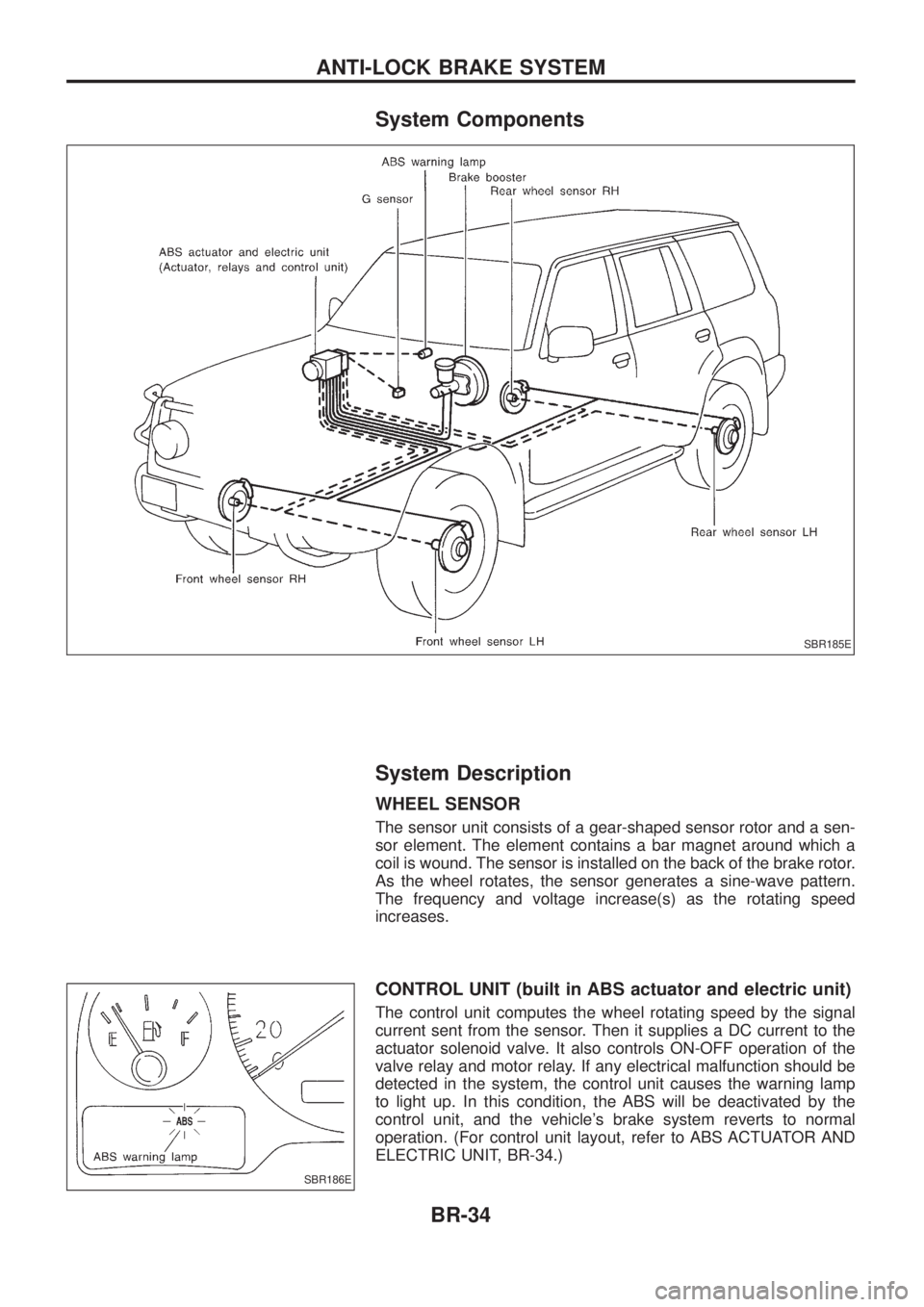
System Components
System Description
WHEEL SENSOR
The sensor unit consists of a gear-shaped sensor rotor and a sen-
sor element. The element contains a bar magnet around which a
coil is wound. The sensor is installed on the back of the brake rotor.
As the wheel rotates, the sensor generates a sine-wave pattern.
The frequency and voltage increase(s) as the rotating speed
increases.
CONTROL UNIT (built in ABS actuator and electric unit)
The control unit computes the wheel rotating speed by the signal
current sent from the sensor. Then it supplies a DC current to the
actuator solenoid valve. It also controls ON-OFF operation of the
valve relay and motor relay. If any electrical malfunction should be
detected in the system, the control unit causes the warning lamp
to light up. In this condition, the ABS will be deactivated by the
control unit, and the vehicle's brake system reverts to normal
operation. (For control unit layout, refer to ABS ACTUATOR AND
ELECTRIC UNIT, BR-34.)
SBR185E
SBR186E
ANTI-LOCK BRAKE SYSTEM
BR-34
Page 40 of 1226
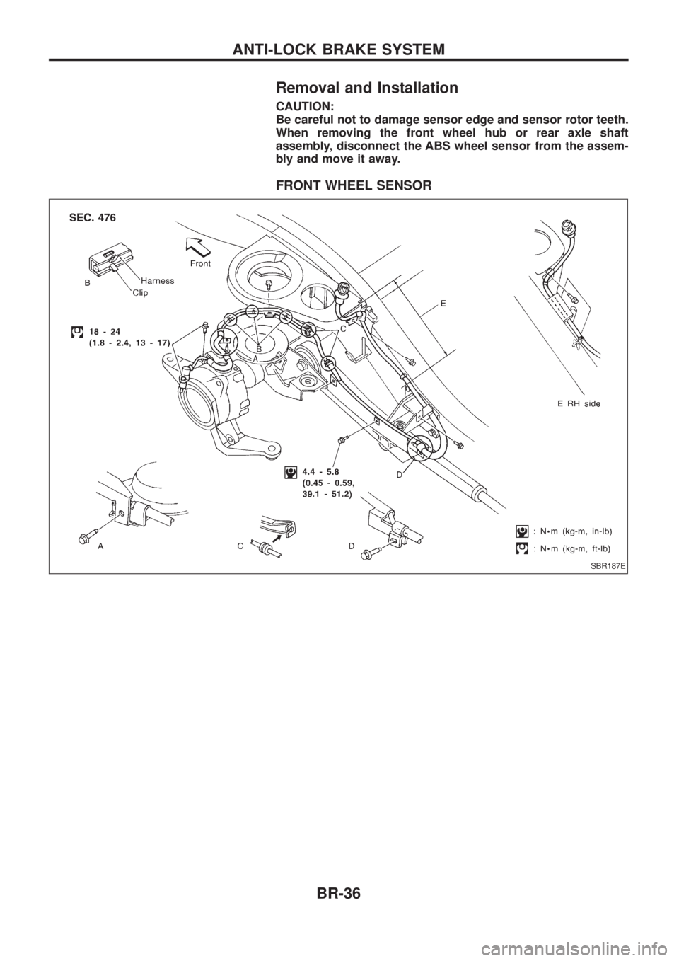
Removal and Installation
CAUTION:
Be careful not to damage sensor edge and sensor rotor teeth.
When removing the front wheel hub or rear axle shaft
assembly, disconnect the ABS wheel sensor from the assem-
bly and move it away.
FRONT WHEEL SENSOR
SBR187E
ANTI-LOCK BRAKE SYSTEM
BR-36