Page 1 of 1226
Edition: February 1998
Release: February 1998 (01)
Publication No.: SM8E-0Y61E0E
Reference No.: 7711346063GENERAL INFORMATIONGI
MAINTENANCEMA
ENGINE MECHANICALEM
ENGINE LUBRICATION &
COOLING SYSTEMSLC
ENGINE CONTROL SYSTEMEC
ACCELERATOR CONTROL,
FUEL & EXHAUST SYSTEMFE
CLUTCHCL
MANUAL TRANSMISSIONMT
AUTOMATIC TRANSMISSIONAT
TRANSFERTF
PROPELLER SHAFT &
DIFFERENTIAL CARRIERPD
FRONT AXLE & FRONT SUSPENSIONFA
REAR AXLE & REAR SUSPENSIONRA
BRAKE SYSTEMBR
STEERING SYSTEMST
RESTRAINT SYSTEMRS
BODY & TRIMBT
HEATER & AIR CONDITIONERHA
ELECTRICAL SYSTEMEL
ALPHABETICAL INDEXIDX
PATROL GR
MODEL Y61 SERIES
NISSAN EUROPE S.A.S.
1998 NISSAN EUROPE S.A.S.
Produced in The Netherlands
Not to be reproduced in whole or in part
without the prior written permission of
Nissan Europe S.A.S., Paris, France.
QUICK REFERENCE INDEX
Page 73 of 1226

Note: ABS may operate and cause vibration under any of thefollowing conditions.
+ Applying brake gradually when shifting or operating
clutch.
+ Low friction (slippery) road.
+ High speed cornering.
+ Driving over bumps and pot holes.
+ Engine speed is over 5,000 rpm with vehicle stopped.
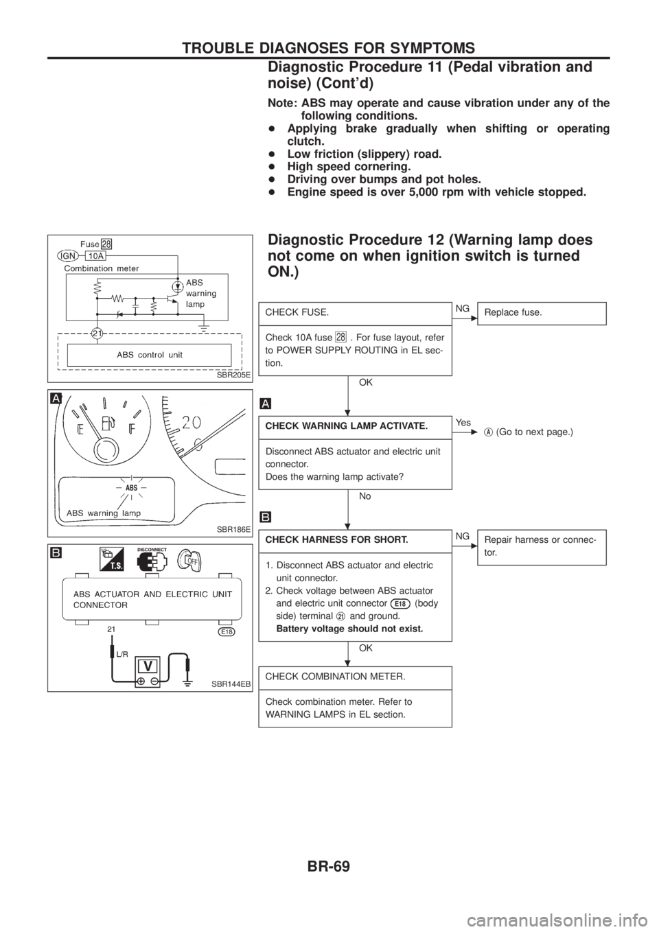
Diagnostic Procedure 12 (Warning lamp does
not come on when ignition switch is turned
ON.)
CHECK FUSE.
- ---------------------------------------------------------------------------------------------------------------------------------------------------------------------------------------------------------------------------------------------------------------------------------------------------------------
Check 10A fuse
28. For fuse layout, refer
to POWER SUPPLY ROUTING in EL sec-
tion.
OK
cNG Replace fuse.
CHECK WARNING LAMP ACTIVATE.
- ---------------------------------------------------------------------------------------------------------------------------------------------------------------------------------------------------------------------------------------------------------------------------------------------------------------
Disconnect ABS actuator and electric unit
connector.
Does the warning lamp activate?
No
cYe s jA(Go to next page.)
CHECK HARNESS FOR SHORT.
- ---------------------------------------------------------------------------------------------------------------------------------------------------------------------------------------------------------------------------------------------------------------------------------------------------------------
1. Disconnect ABS actuator and electric unit connector.
2. Check voltage between ABS actuator and electric unit connector
E18(body
side) terminal j
21and ground.
Battery voltage should not exist.
OK
cNG Repair harness or connec-
tor.
CHECK COMBINATION METER.
- ---------------------------------------------------------------------------------------------------------------------------------------------------------------------------------------------------------------------------------------------------------------------------------------------------------------
Check combination meter. Refer to
WARNING LAMPS in EL section.
SBR205E
SBR186E
SBR144EB
.
.
.
TROUBLE DIAGNOSES FOR SYMPTOMS
Diagnostic Procedure 11 (Pedal vibration and
noise) (Cont'd)
BR-69
Page 125 of 1226
CAB BODY
+Remove following parts in engine room at least.
(1) Main harness and other wiring harness
+Disconnect brake and clutch line in engine compartment.
+Remove following parts from underbody at least.
(1) Transmission and transfer control levers
(2) Parking brake control lever and cable
(3) Main harness and other wiring harness
SBF025E
CAB BODY
BT-47
Page 133 of 1226

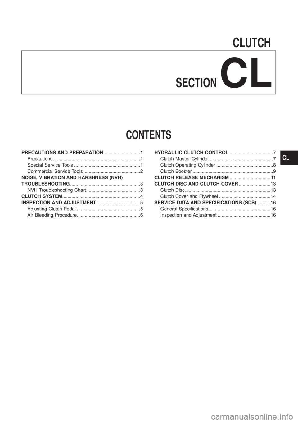
CLUTCH
SECTION
CL
CONTENTS
PRECAUTIONS AND PREPARATION............................1
Precautions ..................................................................1
Special Service Tools ..................................................1
Commercial Service Tools ...........................................2
NOISE, VIBRATION AND HARSHNESS (NVH)
TROUBLESHOOTING.....................................................3
NVH Troubleshooting Chart.........................................3
CLUTCH SYSTEM...........................................................4
INSPECTION AND ADJUSTMENT.................................5
Adjusting Clutch Pedal ................................................5
Air Bleeding Procedure................................................6HYDRAULIC CLUTCH CONTROL.................................7
Clutch Master Cylinder ................................................7
Clutch Operating Cylinder ...........................................8
Clutch Booster .............................................................9
CLUTCH RELEASE MECHANISM............................... 11
CLUTCH DISC AND CLUTCH COVER........................13
Clutch Disc.................................................................13
Clutch Cover and Flywheel .......................................14
SERVICE DATA AND SPECIFICATIONS (SDS)..........16
General Speci®cations ...............................................16
Inspection and Adjustment ........................................16
CL
Page 134 of 1226

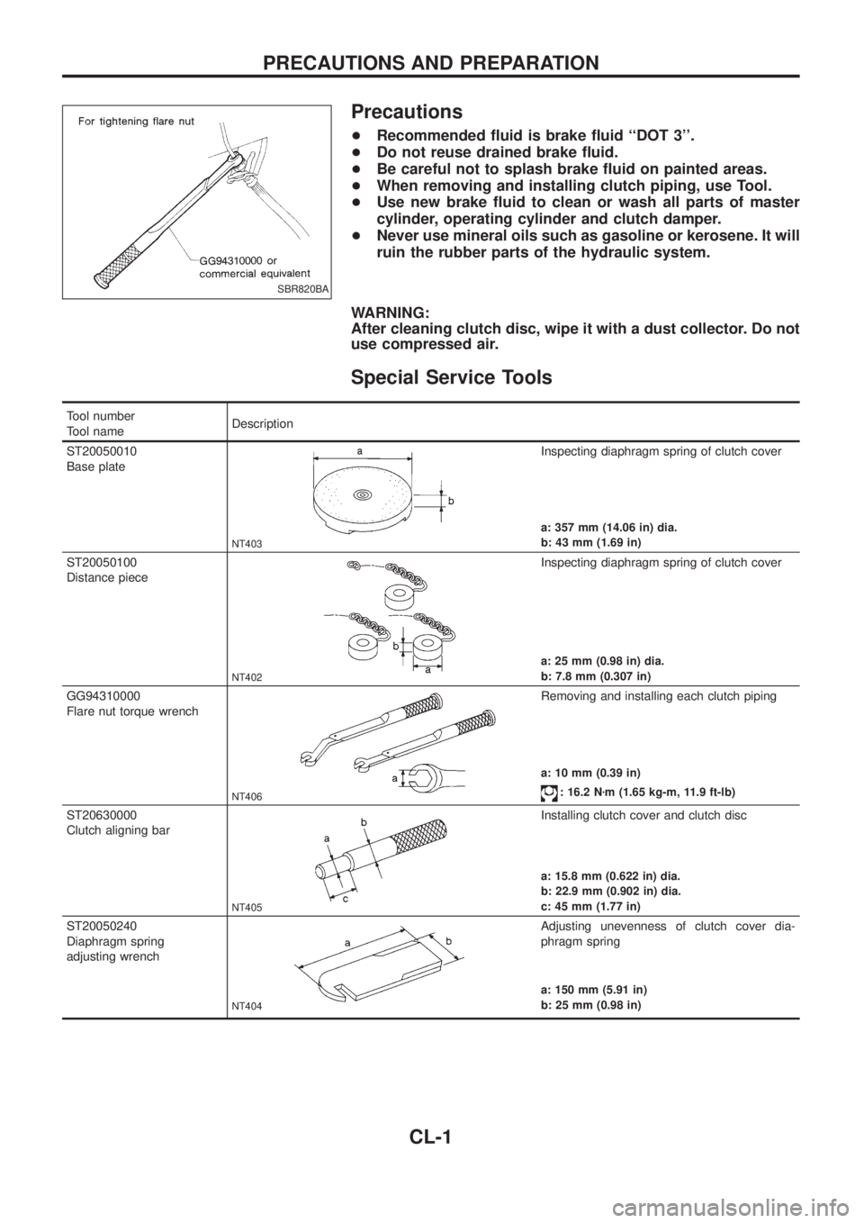
Precautions
+Recommended ¯uid is brake ¯uid ``DOT 3''.
+Do not reuse drained brake ¯uid.
+Be careful not to splash brake ¯uid on painted areas.
+When removing and installing clutch piping, use Tool.
+Use new brake ¯uid to clean or wash all parts of master
cylinder, operating cylinder and clutch damper.
+Never use mineral oils such as gasoline or kerosene. It will
ruin the rubber parts of the hydraulic system.
WARNING:
After cleaning clutch disc, wipe it with a dust collector. Do not
use compressed air.
Special Service Tools
Tool number
Tool nameDescription
ST20050010
Base plate
NT403
Inspecting diaphragm spring of clutch cover
a: 357 mm (14.06 in) dia.
b: 43 mm (1.69 in)
ST20050100
Distance piece
NT402
Inspecting diaphragm spring of clutch cover
a: 25 mm (0.98 in) dia.
b: 7.8 mm (0.307 in)
GG94310000
Flare nut torque wrench
NT406
Removing and installing each clutch piping
a: 10 mm (0.39 in)
: 16.2 Nzm (1.65 kg-m, 11.9 ft-lb)
ST20630000
Clutch aligning bar
NT405
Installing clutch cover and clutch disc
a: 15.8 mm (0.622 in) dia.
b: 22.9 mm (0.902 in) dia.
c: 45 mm (1.77 in)
ST20050240
Diaphragm spring
adjusting wrench
NT404
Adjusting unevenness of clutch cover dia-
phragm spring
a: 150 mm (5.91 in)
b: 25 mm (0.98 in)
SBR820BA
PRECAUTIONS AND PREPARATION
CL-1
Page 135 of 1226
Commercial Service Tools
Tool name Description
V1Flare nut crowfoot
V2Torque wrench
NT684
Removing and installing clutch piping
a: 10 mm (0.39 in)
Bearing puller
NT077
Removing release bearing
Wire
NT727
Installing clutch cover
Wire: 3.2 mm (0.126 in) dia.
Bearing drift
NT474
Installing release bearing
a: 52 mm (2.05 in) dia.
b: 45 mm (1.77 in) dia.
PRECAUTIONS AND PREPARATION
CL-2
Page 136 of 1226

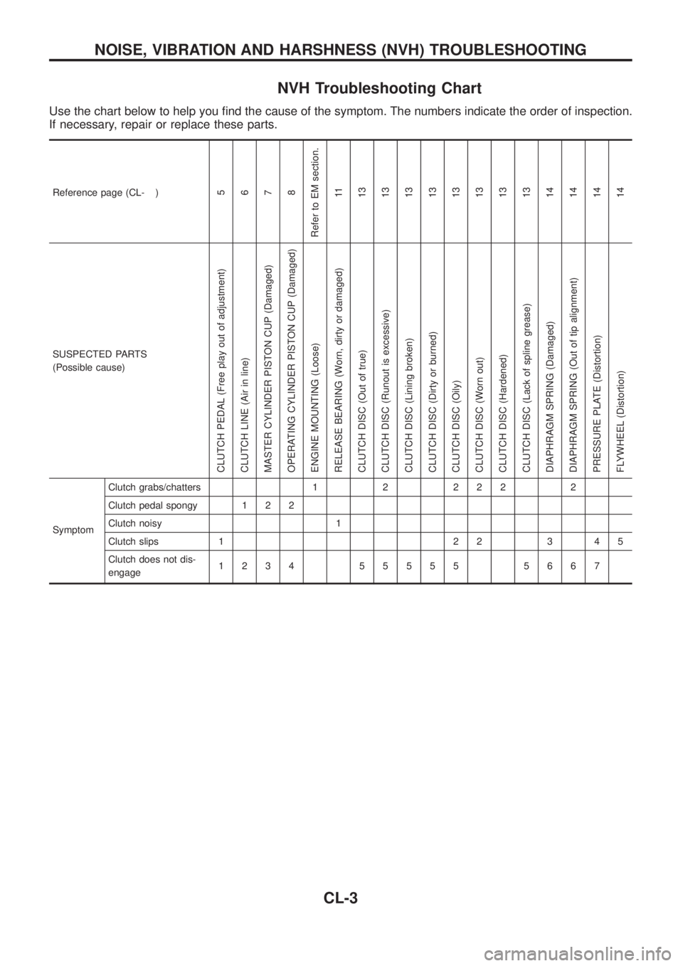
NVH Troubleshooting Chart
Use the chart below to help you ®nd the cause of the symptom. The numbers indicate the order of inspection.
If necessary, repair or replace these parts.
Reference page (CL- )5
6
7
8
Refer to EM section.
11
13
13
13
13
13
13
13
13
14
14
14
14
SUSPECTED PARTS
(Possible cause)
CLUTCH PEDAL (Free play out of adjustment)
CLUTCH LINE (Air in line)
MASTER CYLINDER PISTON CUP (Damaged)
OPERATING CYLINDER PISTON CUP (Damaged)
ENGINE MOUNTING (Loose)
RELEASE BEARING (Worn, dirty or damaged)
CLUTCH DISC (Out of true)
CLUTCH DISC (Runout is excessive)
CLUTCH DISC (Lining broken)
CLUTCH DISC (Dirty or burned)
CLUTCH DISC (Oily)
CLUTCH DISC (Worn out)
CLUTCH DISC (Hardened)
CLUTCH DISC (Lack of spline grease)
DIAPHRAGM SPRING (Damaged)
DIAPHRAGM SPRING (Out of tip alignment)
PRESSURE PLATE (Distortion)
FLYWHEEL (Distortion)
SymptomClutch grabs/chatters 1 2 2 2 2 2
Clutch pedal spongy 1 2 2
Clutch noisy 1
Clutch slips 1 2 2 3 4 5
Clutch does not dis-
engage1234 55555 5667
NOISE, VIBRATION AND HARSHNESS (NVH) TROUBLESHOOTING
CL-3
Page 137 of 1226
SCL768
CLUTCH SYSTEM
CL-4