Page 146 of 1226
Clutch Disc
INSPECTION
Check clutch disc for wear of facing.
Wear limit of facing surface to rivet head:
0.3 mm (0.012 in)
+Check clutch disc for backlash of spline and runout of facing.
Maximum backlash of spline (at outer edge of disc):
Model 240
1.0 mm (0.039 in)
Runout limit:
Model 240
0.7 mm (0.028 in)
Distance of runout check point (from hub center):
Model 240
115.0 mm (4.53 in)
+Check clutch disc for burns, discoloration or oil or grease leak-
age. Replace if necessary.
INSTALLATION
+Apply recommended grease to contact surface of spline por-
tion.
Too much lubricant might cause clutch disc facing damage.
SCL778
SCL780
SCL779
CLUTCH DISC AND CLUTCH COVER
CL-13
Page 147 of 1226

Clutch Cover and Flywheel
INSPECTION
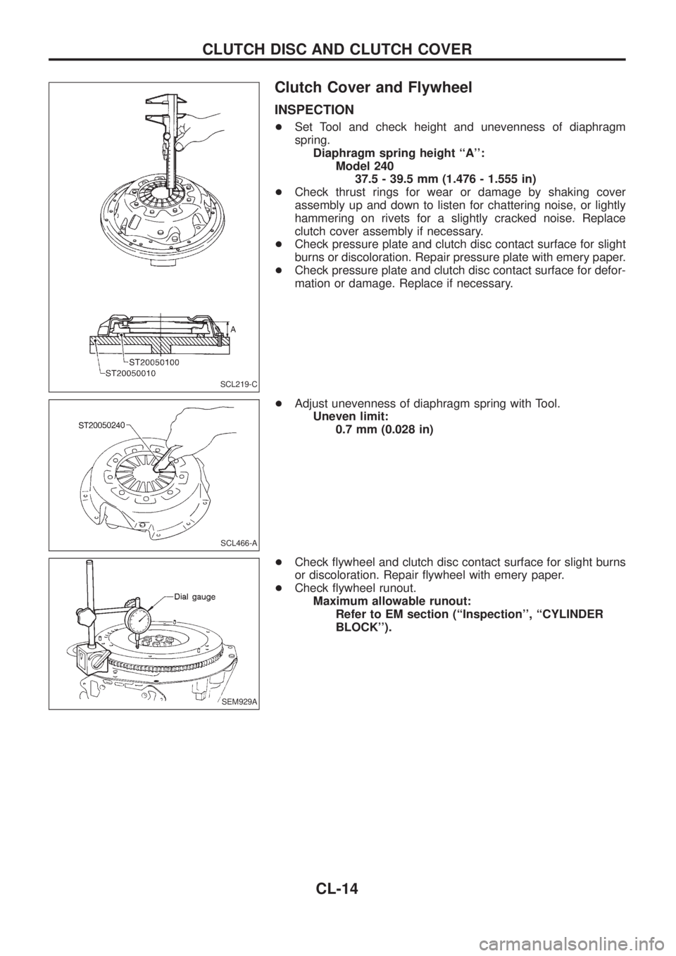
+Set Tool and check height and unevenness of diaphragm
spring.
Diaphragm spring height ``A'':
Model 240
37.5 - 39.5 mm (1.476 - 1.555 in)
+Check thrust rings for wear or damage by shaking cover
assembly up and down to listen for chattering noise, or lightly
hammering on rivets for a slightly cracked noise. Replace
clutch cover assembly if necessary.
+Check pressure plate and clutch disc contact surface for slight
burns or discoloration. Repair pressure plate with emery paper.
+Check pressure plate and clutch disc contact surface for defor-
mation or damage. Replace if necessary.
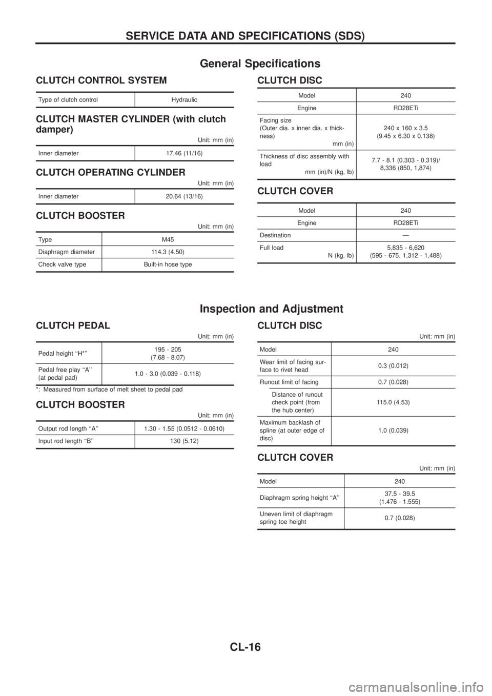
+Adjust unevenness of diaphragm spring with Tool.
Uneven limit:
0.7 mm (0.028 in)
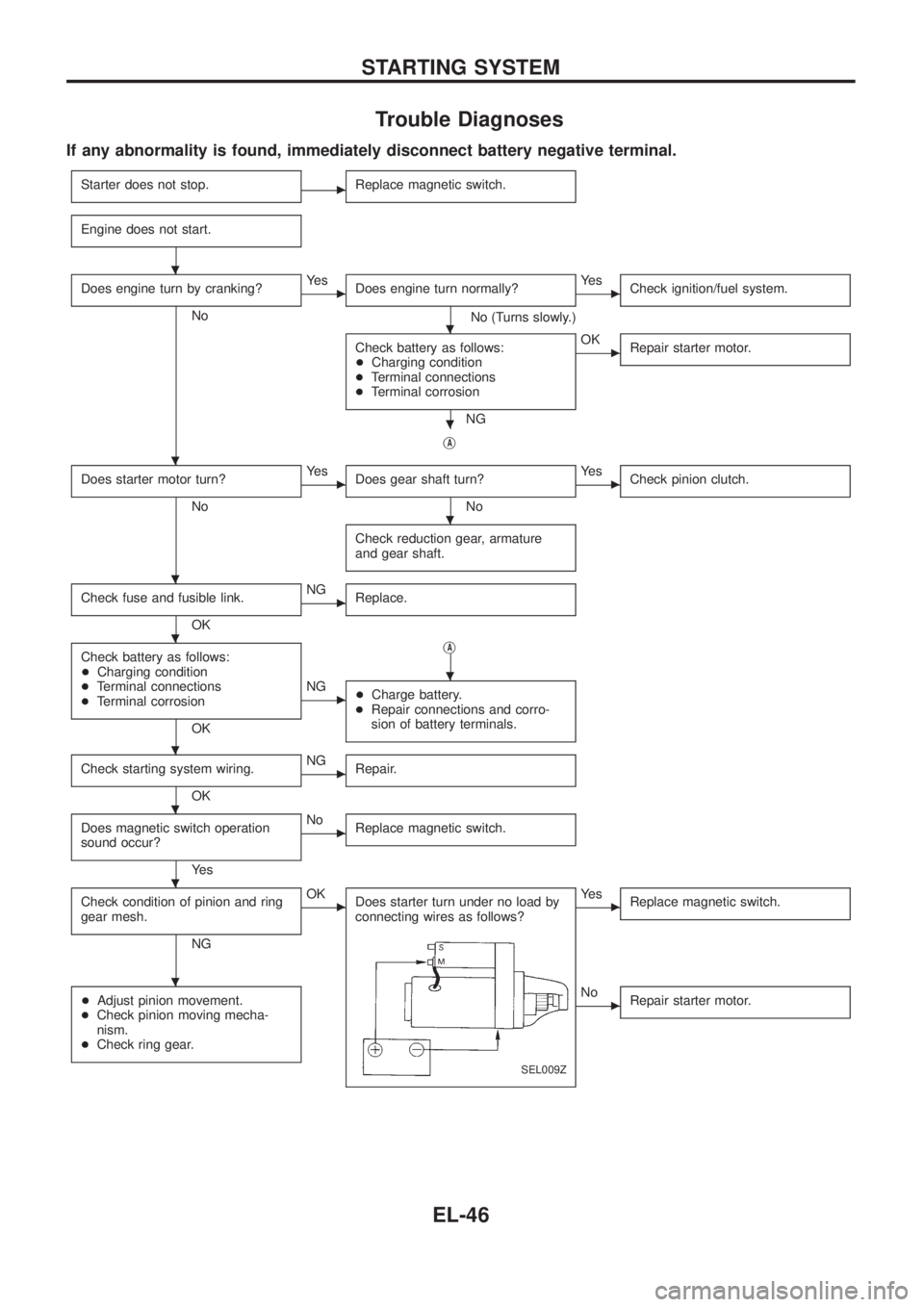
+Check ¯ywheel and clutch disc contact surface for slight burns
or discoloration. Repair ¯ywheel with emery paper.
+Check ¯ywheel runout.
Maximum allowable runout:
Refer to EM section (``Inspection'', ``CYLINDER
BLOCK'').
SCL219-C
SCL466-A
SEM929A
CLUTCH DISC AND CLUTCH COVER
CL-14
Page 148 of 1226
INSTALLATION
Model 240
+Insert Tool into clutch disc hub while installing clutch cover and
disc.
+Be careful not to allow grease to contaminate clutch facing.
+Tighten bolts in numerical order, in two steps.
First step:
:10-20Nzm (1.0 - 2.0 kg-m,7-14ft-lb)
Final step:
:22-29Nzm (2.2 - 3.0 kg-m, 16 - 22 ft-lb)
SCL787
CLUTCH DISC AND CLUTCH COVER
Clutch Cover and Flywheel (Cont'd)
CL-15
Page 149 of 1226

General Speci®cations
CLUTCH CONTROL SYSTEM
Type of clutch control Hydraulic
CLUTCH MASTER CYLINDER (with clutch
damper)
Unit: mm (in)
Inner diameter 17.46 (11/16)
CLUTCH OPERATING CYLINDER
Unit: mm (in)
Inner diameter 20.64 (13/16)
CLUTCH BOOSTER
Unit: mm (in)
Type M45
Diaphragm diameter 114.3 (4.50)
Check valve type Built-in hose type
CLUTCH DISC
Model 240
Engine RD28ETi
Facing size
(Outer dia. x inner dia. x thick-
ness)
mm (in)240 x 160 x 3.5
(9.45 x 6.30 x 0.138)
Thickness of disc assembly with
load
mm (in)/N (kg, lb)7.7 - 8.1 (0.303 - 0.319)/
8,336 (850, 1,874)
CLUTCH COVER
Model 240
Engine RD28ETi
Destination Ð
Full load
N (kg, lb)5,835 - 6,620
(595 - 675, 1,312 - 1,488)
Inspection and Adjustment
CLUTCH PEDAL
Unit: mm (in)
Pedal height ``H*''195 - 205
(7.68 - 8.07)
Pedal free play ``A''
(at pedal pad)1.0 - 3.0 (0.039 - 0.118)
*: Measured from surface of melt sheet to pedal pad
CLUTCH BOOSTER
Unit: mm (in)
Output rod length ``A'' 1.30 - 1.55 (0.0512 - 0.0610)
Input rod length ``B'' 130 (5.12)
CLUTCH DISC
Unit: mm (in)
Model 240
Wear limit of facing sur-
face to rivet head0.3 (0.012)
Runout limit of facing 0.7 (0.028)
Distance of runout
check point (from
the hub center)115.0 (4.53)
Maximum backlash of
spline (at outer edge of
disc)1.0 (0.039)
CLUTCH COVER
Unit: mm (in)
Model 240
Diaphragm spring height ``A''37.5 - 39.5
(1.476 - 1.555)
Uneven limit of diaphragm
spring toe height0.7 (0.028)
SERVICE DATA AND SPECIFICATIONS (SDS)
CL-16
Page 391 of 1226

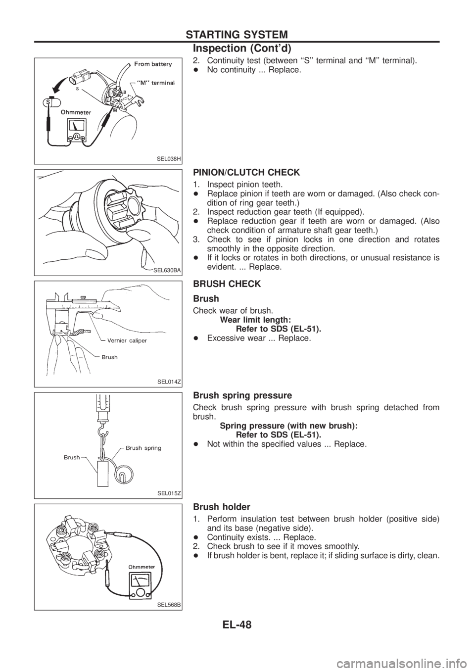
Trouble Diagnoses
If any abnormality is found, immediately disconnect battery negative terminal.
Starter does not stop.cReplace magnetic switch.
Engine does not start.
Does engine turn by cranking?
No
cYe s
Does engine turn normally?
No (Turns slowly.)
cYe s
Check ignition/fuel system.
Check battery as follows:
+Charging condition
+Terminal connections
+Terminal corrosion
NG
cOK
Repair starter motor.
jA
Does starter motor turn?
No
cYe s
Does gear shaft turn?
No
cYe s
Check pinion clutch.
Check reduction gear, armature
and gear shaft.
Check fuse and fusible link.
OK
cNG
Replace.
Check battery as follows:
+Charging condition
+Terminal connections
+Terminal corrosion
OKj
A
cNG
+Charge battery.
+Repair connections and corro-
sion of battery terminals.
Check starting system wiring.
OK
cNG
Repair.
Does magnetic switch operation
sound occur?
Ye s
cNo
Replace magnetic switch.
Check condition of pinion and ring
gear mesh.
NG
cOK
Does starter turn under no load by
connecting wires as follows?
SEL009Z
cYe s
Replace magnetic switch.
+Adjust pinion movement.
+Check pinion moving mecha-
nism.
+Check ring gear.cNo
Repair starter motor.
.
.
.
.
.
.
.
.
.
.
.
.
STARTING SYSTEM
EL-46
Page 393 of 1226

2. Continuity test (between ``S'' terminal and ``M'' terminal).
+No continuity ... Replace.
PINION/CLUTCH CHECK
1. Inspect pinion teeth.
+Replace pinion if teeth are worn or damaged. (Also check con-
dition of ring gear teeth.)
2. Inspect reduction gear teeth (If equipped).
+Replace reduction gear if teeth are worn or damaged. (Also
check condition of armature shaft gear teeth.)
3. Check to see if pinion locks in one direction and rotates
smoothly in the opposite direction.
+If it locks or rotates in both directions, or unusual resistance is
evident. ... Replace.
BRUSH CHECK
Brush
Check wear of brush.
Wear limit length:
Refer to SDS (EL-51).
+Excessive wear ... Replace.
Brush spring pressure
Check brush spring pressure with brush spring detached from
brush.
Spring pressure (with new brush):
Refer to SDS (EL-51).
+Not within the speci®ed values ... Replace.
Brush holder
1. Perform insulation test between brush holder (positive side)
and its base (negative side).
+Continuity exists. ... Replace.
2. Check brush to see if it moves smoothly.
+If brush holder is bent, replace it; if sliding surface is dirty, clean.
SEL038H
SEL630BA
SEL014Z
SEL015Z
SEL568B
STARTING SYSTEM
Inspection (Cont'd)
EL-48
Page 691 of 1226
CRANKSHAFT REAR OIL SEAL
1. Remove transmission assembly. (Refer to ``REMOVAL AND
INSTALLATION'' in MT section.)
2. Remove clutch cover assembly.
3. Remove ¯ywheel and rear plate.
4. Remove oil pan and oil pan gasket.
5. Remove oil seal retainer assembly.
6. Remove traces of liquid gasket using a scraper.
7. Remove rear oil seal from retainer.
8. Apply engine oil to new oil seal and install oil seal using a suit-
able tool.
9. Apply a continuous bead of liquid gasket to rear oil seal
retainer.
a. Coat of liquid gasket should be maintained within 2.0 to 3.0
mm (0.079 to 0.118 in) dia. range.
b. Attach oil seal retainer to cylinder block within ®ve min-
utes after coating.
c. Wait at least 30 minutes before re®lling engine oil or start-
ing engine.
d. Use Genuine Liquid Gasket or equivalent.
SEM896A
SEM895A
SEM897A
SLC822
SEM144B
OIL SEAL REPLACEMENT
EM-23
Page 744 of 1226
Removal
1. Set knob of manual-lock free-running hub to the ``FREE'' posi-
tion.
2. Loosen bolts and remove free-running hub assembly.
3. Remove snap ring and take off drive clutch.
4. Take out bushing and spacer from wheel hub.
SFA427AA
SFA428A
SFA187
SFA188
SFA189
FRONT AXLE Ð Manual-lock Free-running Hub
FA-11