2006 NISSAN PATROL stop lamp
[x] Cancel search: stop lampPage 4 of 1226
Ground Circuit Check ................................................56
TROUBLE DIAGNOSES FOR SELF-DIAGNOSTIC
ITEMS ........................................................................\
.....57
Diagnostic Procedure 1 (Wheel sensor or rotor) ......57
Diagnostic Procedure 2 (ABS actuator solenoid
valve and solenoid valve relay) .................................59
Diagnostic Procedure 3 (Motor relay or motor).........61
Diagnostic Procedure 4 (Low voltage) ......................63
Diagnostic Procedure 5 (G sensor) ...........................64
Diagnostic Procedure 6 (Control unit) .......................65
TROUBLE DIAGNOSES FOR SYMPTOMS .................66
Diagnostic Procedure 7 (ABS works frequently.) ......66
Diagnostic Procedure 8 (Unexpected pedal
action) ........................................................................\
67 Diagnostic Procedure 9 (Long stopping distance) ....67
Diagnostic Procedure 10 (ABS does not work.) .......68
Diagnostic Procedure 11 (Pedal vibration and
noise) ........................................................................\
.68
Diagnostic Procedure 12 (Warning lamp does
not come on when ignition switch is turned ON.) .....69
Diagnostic Procedure 13 (Warning lamp stays on
when ignition switch is turned ON.)...........................71
SERVICE DATA AND SPECIFICATIONS (SDS) ..........72
General Speci®cations ...............................................72
Inspection and Adjustment ........................................73
When you read wiring diagrams:
+ Read GI section, ``HOW TO READ WIRING DIAGRAMS''.
+ See EL section, ``POWER SUPPLY ROUTING'' for power distribution circuit.
When you perform trouble diagnoses, read GI section, ``HOW TO FOLLOW FLOW CHART
IN TROUBLE DIAGNOSES'' and ``HOW TO PERFORM EFFICIENT DIAGNOSIS FOR AN
ELECTRICAL INCIDENT''.
Page 14 of 1226

Removal and Installation
Inspection
Check brake pedal for following items.
+Brake pedal bend
+ Clevis pin deformation
+ Crack of any welded portion
+ Crack or deformation of clevis pin stopper
Adjustment
Check brake pedal free height from dash lower panel.
H: Free height Refer to SDS (BR-72).
D: Depressed height Refer to SDS (BR-72).
Under force of 490 N (50 kg, 110 lb)
with engine running
C
1,C2: Clearance between pedal stopper and threaded end of stop lamp switch and ASCD
switch 0.3 - 1.0 mm (0.012 - 0.039 in)
A: Pedal free play 1-3mm(0.04 - 0.12 in)
If necessary, adjust brake pedal free height.
SBR163E
SBR463CB
BRAKE PEDAL AND BRACKET
BR-10
Page 15 of 1226

1. Loosen lock nut and adjust pedal free height by turning brakebooster input rod. Then tighten lock nut.
Make sure that tip of input rod stays inside.
2. Adjust clearance ``C
1'' and ``C2'' with stop lamp switch and
ASCD switch respectively. Then tighten lock nuts.
3. Check pedal free play.
Make sure that stop lamp is off when pedal is released.
4. Check brake pedal's depressed height while engine is running. If depressed height is below speci®ed value, check brake sys-
tem for leaks, accumulation of air or any damage to compo-
nents (master cylinder, wheel cylinder, etc.). Then make nec-
essary repairs.
SBR824B
BRAKE PEDAL AND BRACKET
Adjustment (Cont'd)
BR-11
Page 53 of 1226
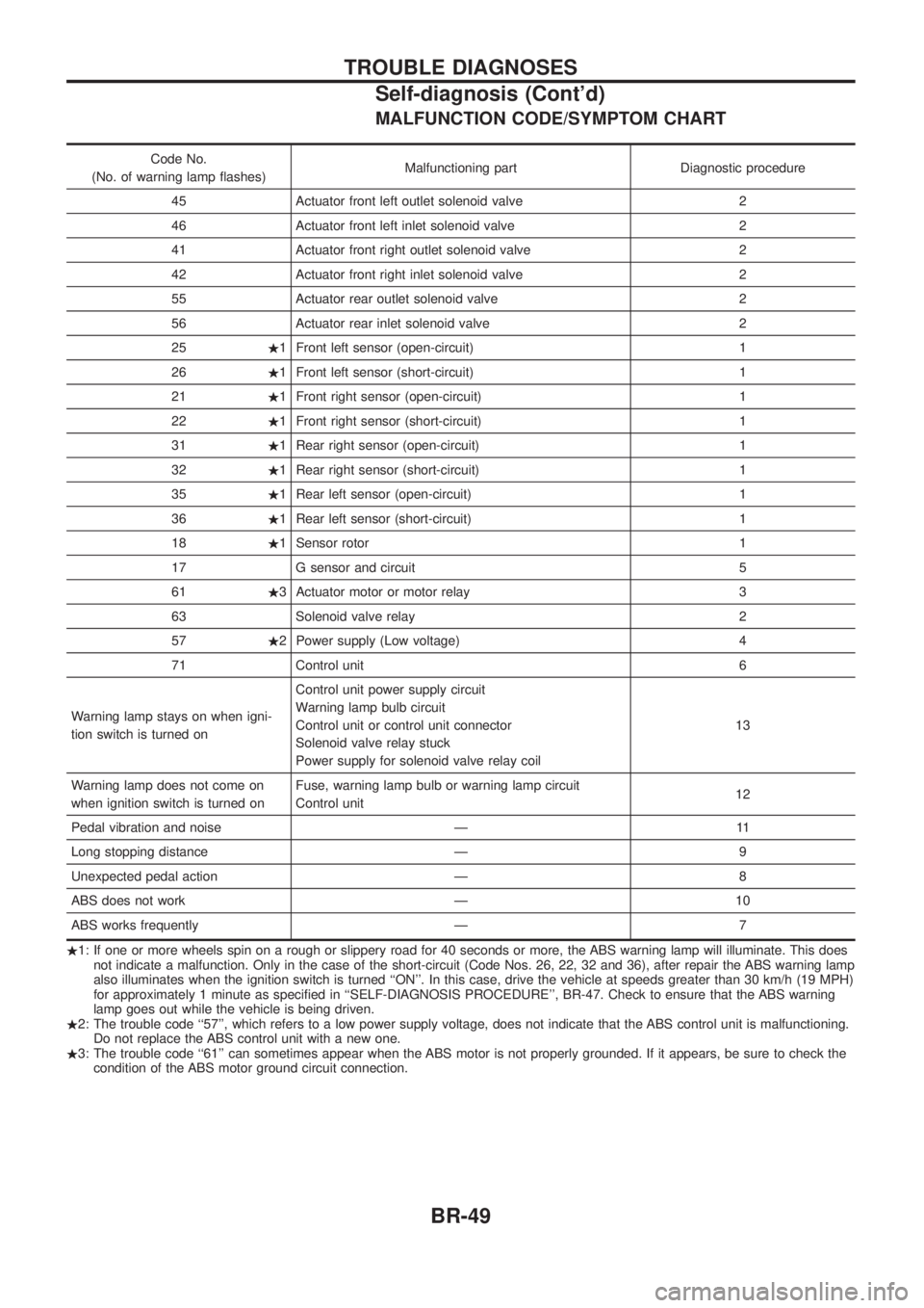
MALFUNCTION CODE/SYMPTOM CHART
Code No.
(No. of warning lamp ¯ashes) Malfunctioning part Diagnostic procedure
45 Actuator front left outlet solenoid valve 2
46 Actuator front left inlet solenoid valve 2
41 Actuator front right outlet solenoid valve 2
42 Actuator front right inlet solenoid valve 2
55 Actuator rear outlet solenoid valve 2
56 Actuator rear inlet solenoid valve 2
25 .1 Front left sensor (open-circuit) 1
26 .1 Front left sensor (short-circuit) 1
21 .1 Front right sensor (open-circuit) 1
22 .1 Front right sensor (short-circuit) 1
31 .1 Rear right sensor (open-circuit) 1
32 .1 Rear right sensor (short-circuit) 1
35 .1 Rear left sensor (open-circuit) 1
36 .1 Rear left sensor (short-circuit) 1
18 .1 Sensor rotor 1
17 G sensor and circuit 5
61 .3 Actuator motor or motor relay 3
63 Solenoid valve relay 2
57 .2 Power supply (Low voltage) 4
71 Control unit 6
Warning lamp stays on when igni-
tion switch is turned on Control unit power supply circuit
Warning lamp bulb circuit
Control unit or control unit connector
Solenoid valve relay stuck
Power supply for solenoid valve relay coil
13
Warning lamp does not come on
when ignition switch is turned on Fuse, warning lamp bulb or warning lamp circuit
Control unit
12
Pedal vibration and noise Ð 11
Long stopping distance Ð 9
Unexpected pedal action Ð 8
ABS does not work Ð 10
ABS works frequently Ð 7
. 1: If one or more wheels spin on a rough or slippery road for 40 seconds or more, the ABS warning lamp will illuminate. This does
not indicate a malfunction. Only in the case of the short-circuit (Code Nos. 26, 22, 32 and 36), after repair the ABS warning lamp
also illuminates when the ignition switch is turned ``ON''. In this case, drive the vehicle at speeds greater than 30 km/h (19 MPH)
for approximately 1 minute as speci®ed in ``SELF-DIAGNOSIS PROCEDURE'', BR-47. Check to ensure that the ABS warning
lamp goes out while the vehicle is being driven.
. 2: The trouble code ``57'', which refers to a low power supply voltage, does not indicate that the ABS control unit is malfunctioning.
Do not replace the ABS control unit with a new one.
. 3: The trouble code ``61'' can sometimes appear when the ABS motor is not properly grounded. If it appears, be sure to check the
condition of the ABS motor ground circuit connection.
TROUBLE DIAGNOSES
Self-diagnosis (Cont'd)
BR-49
Page 54 of 1226
CONSULT
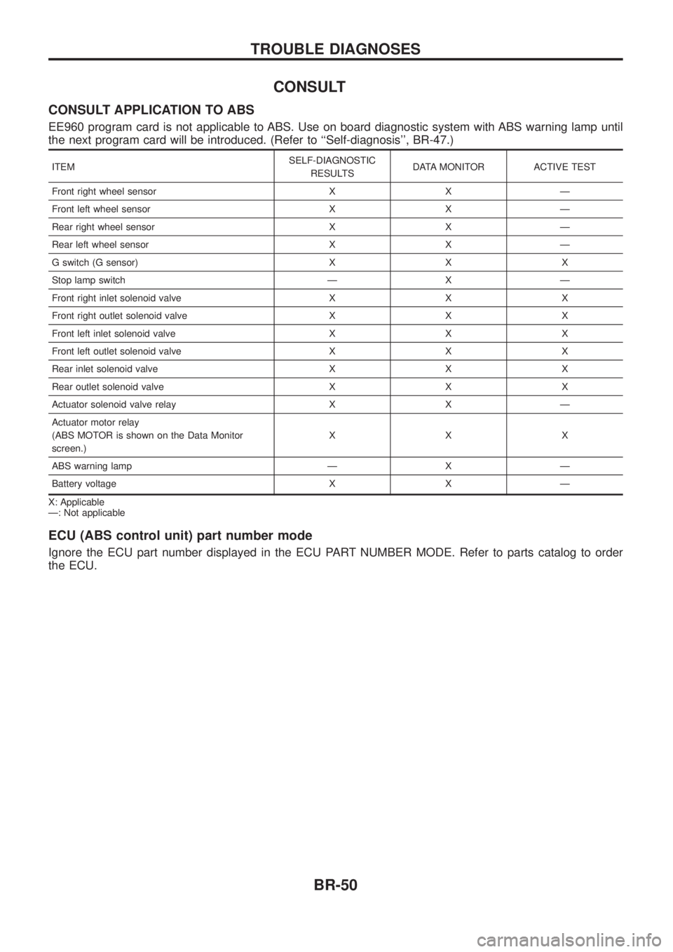
CONSULT APPLICATION TO ABS
EE960 program card is not applicable to ABS. Use on board diagnostic system with ABS warning lamp until
the next program card will be introduced. (Refer to ``Self-diagnosis'', BR-47.)
ITEMSELF-DIAGNOSTIC
RESULTS DATA MONITOR ACTIVE TEST
Front right wheel sensor X X Ð
Front left wheel sensor X X Ð
Rear right wheel sensor X X Ð
Rear left wheel sensor X X Ð
G switch (G sensor) X X X
Stop lamp switch Ð X Ð
Front right inlet solenoid valve X X X
Front right outlet solenoid valve X X X
Front left inlet solenoid valve X X X
Front left outlet solenoid valve X X X
Rear inlet solenoid valve X X X
Rear outlet solenoid valve X X X
Actuator solenoid valve relay X X Ð
Actuator motor relay
(ABS MOTOR is shown on the Data Monitor
screen.) XXX
ABS warning lamp Ð X Ð
Battery voltage X X Ð
X: Applicable
Ð: Not applicable
ECU (ABS control unit) part number mode
Ignore the ECU part number displayed in the ECU PART NUMBER MODE. Refer to parts catalog to order
the ECU.
TROUBLE DIAGNOSES
BR-50
Page 55 of 1226
CONSULT Inspection Procedure
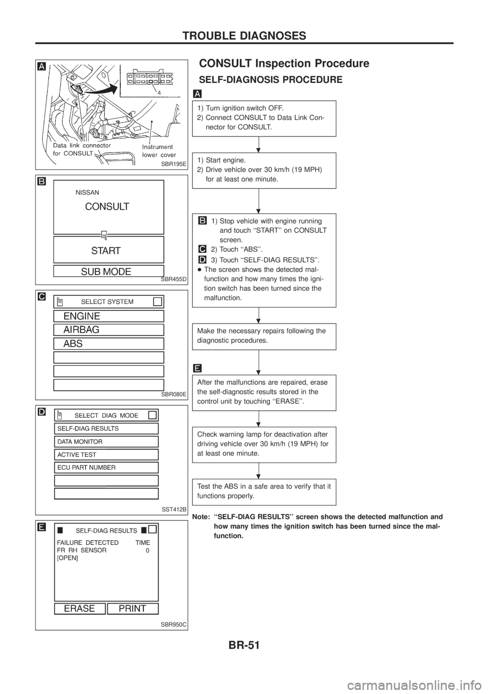
SELF-DIAGNOSIS PROCEDURE
1) Turn ignition switch OFF.
2) Connect CONSULT to Data Link Con- nector for CONSULT.
1) Start engine.
2) Drive vehicle over 30 km/h (19 MPH) for at least one minute.
1) Stop vehicle with engine runningand touch ``START'' on CONSULT
screen.
2) Touch ``ABS''.
3) Touch ``SELF-DIAG RESULTS''.
+ The screen shows the detected mal-
function and how many times the igni-
tion switch has been turned since the
malfunction.
Make the necessary repairs following the
diagnostic procedures.
After the malfunctions are repaired, erase
the self-diagnostic results stored in the
control unit by touching ``ERASE''.
Check warning lamp for deactivation after
driving vehicle over 30 km/h (19 MPH) for
at least one minute.
Test the ABS in a safe area to verify that it
functions properly.
Note: ``SELF-DIAG RESULTS'' screen shows the detected malfunction and how many times the ignition switch has been turned since the mal-
function.
SBR195E
SBR455D
SBR080E
SST412B
SBR950C
.
.
.
.
.
.
TROUBLE DIAGNOSES
BR-51
Page 59 of 1226

DATA MONITOR MODE
MONITOR ITEM CONDITION SPECIFICATION
FR RH SENSOR
FR LH SENSOR
RR SENSOR
RR RH SENSOR
RR LH SENSORDrive vehicle.
(Each wheel is rotating.)
Wheel speed signal
(Almost the same speed as speedometer.)
STOP LAMP SW Brake is depressed. Depress the pedal: ON
Release the pedal: OFF
G-SWITCH Vehicle is driven.
Vehicle is stopped.
Brake is applied.During sudden braking while driving on high roads (asphalt
roads, etc.): OFF
While vehicle is stopped or during constant-speed driving: ON
FR RH IN SOL
FR RH OUT SOL
FR LH IN SOL
FR LH OUT SOL
RR IN SOL
RR OUT SOL 1. Drive vehicle at speeds over
30 km/h (19 MPH) for at
least one minute.
2. Engine is running. Operating conditions for each solenoid valve are indicated.
ABS is not operating: OFF
MOTOR RELAY ABS is not operating: OFF
ABS is operating: ON
ACTUATOR RELAY Ignition switch is ON or
engine is running.Ignition switch ON (Engine stops): OFF
Engine running: ON
WARNING LAMP ABS warning lamp is turned on: ON
ABS warning lamp is turned off: OFF
BATTERY VOLT Power supply voltage for control unit
ACTIVE TEST MODE
TEST ITEM CONDITION JUDGEMENT
FR RH SOLENOID
FR LH SOLENOID
REAR SOLENOID Engine is running.Brake ¯uid pressure control operation
IN SOL OUT SOL
UP (Increase):
KEEP (Hold):
DOWN (Decrease): OFF
ON
ONOFF
OFF
ON
ABS MOTOR ABS actuator motor
ON: Motor runs (ABS motor relay ON)
OFF: Motor stops (ABS motor relay OFF)
G SWITCH Ignition switch is ON. G SWITCH (G SENSOR),
ON: Set G SWITCH MONITOR ``ON''
(G switch circuit is closed.)
OFF: Set G SWITCH MONITOR ``OFF'' (G switch circuit is open.)
Note: Active test will automatically stop ten seconds after the test starts. (LIMIT SIGNAL monitor shows ON.)
TROUBLE DIAGNOSES
CONSULT Inspection Procedure (Cont'd)
BR-55
Page 71 of 1226
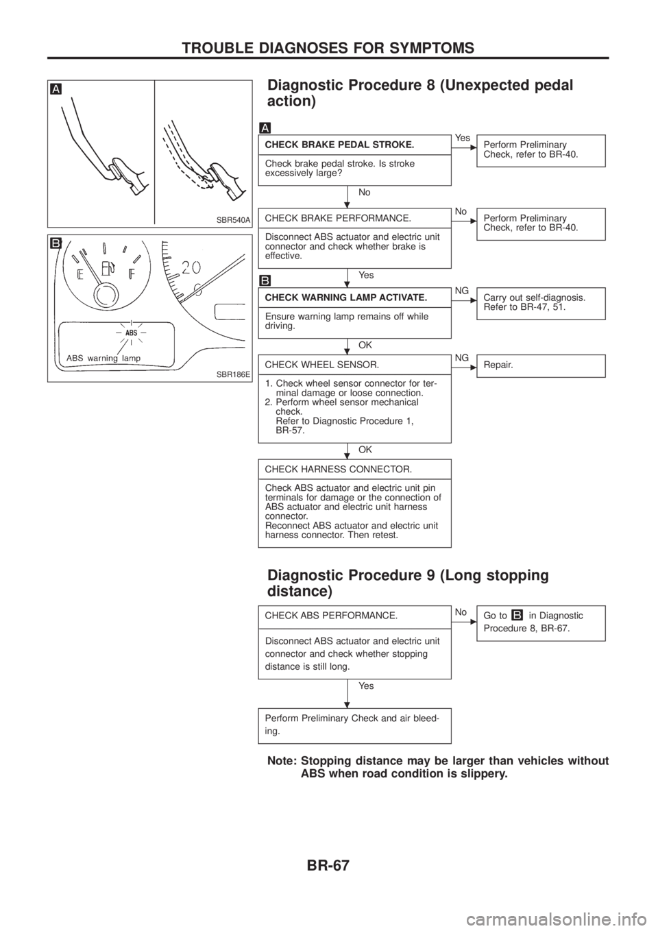
Diagnostic Procedure 8 (Unexpected pedal
action)
CHECK BRAKE PEDAL STROKE.
- ---------------------------------------------------------------------------------------------------------------------------------------------------------------------------------------------------------------------------------------------------------------------------------------------------------------
Check brake pedal stroke. Is stroke
excessively large?
No
cYe s Perform Preliminary
Check, refer to BR-40.
CHECK BRAKE PERFORMANCE.
- ---------------------------------------------------------------------------------------------------------------------------------------------------------------------------------------------------------------------------------------------------------------------------------------------------------------
Disconnect ABS actuator and electric unit
connector and check whether brake is
effective.
Ye s
cNo Perform Preliminary
Check, refer to BR-40.
CHECK WARNING LAMP ACTIVATE.
- ---------------------------------------------------------------------------------------------------------------------------------------------------------------------------------------------------------------------------------------------------------------------------------------------------------------
Ensure warning lamp remains off while
driving.
OK
cNG Carry out self-diagnosis.
Refer to BR-47, 51.
CHECK WHEEL SENSOR.
- ---------------------------------------------------------------------------------------------------------------------------------------------------------------------------------------------------------------------------------------------------------------------------------------------------------------
1. Check wheel sensor connector for ter- minal damage or loose connection.
2. Perform wheel sensor mechanical check.
Refer to Diagnostic Procedure 1,
BR-57.
OK
cNG Repair.
CHECK HARNESS CONNECTOR.
- ---------------------------------------------------------------------------------------------------------------------------------------------------------------------------------------------------------------------------------------------------------------------------------------------------------------
Check ABS actuator and electric unit pin
terminals for damage or the connection of
ABS actuator and electric unit harness
connector.
Reconnect ABS actuator and electric unit
harness connector. Then retest.
Diagnostic Procedure 9 (Long stopping
distance)
CHECK ABS PERFORMANCE.
- ---------------------------------------------------------------------------------------------------------------------------------------------------------------------------------------------------------------------------------------------------------------------------------------------------------------
Disconnect ABS actuator and electric unit
connector and check whether stopping
distance is still long.
Ye s
cNo Go toin Diagnostic
Procedure 8, BR-67.
Perform Preliminary Check and air bleed-
ing.
Note: Stopping distance may be larger than vehicles without ABS when road condition is slippery.
SBR540A
SBR186E
.
.
.
.
.
TROUBLE DIAGNOSES FOR SYMPTOMS
BR-67