Page 73 of 1226
Note: ABS may operate and cause vibration under any of thefollowing conditions.
+ Applying brake gradually when shifting or operating
clutch.
+ Low friction (slippery) road.
+ High speed cornering.
+ Driving over bumps and pot holes.
+ Engine speed is over 5,000 rpm with vehicle stopped.
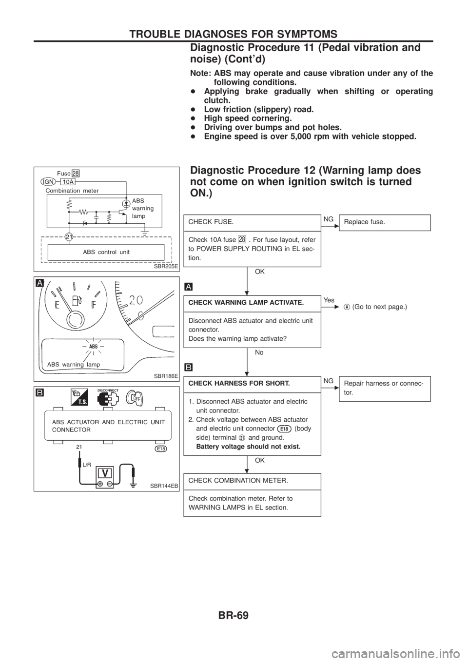
Diagnostic Procedure 12 (Warning lamp does
not come on when ignition switch is turned
ON.)
CHECK FUSE.
- ---------------------------------------------------------------------------------------------------------------------------------------------------------------------------------------------------------------------------------------------------------------------------------------------------------------
Check 10A fuse
28. For fuse layout, refer
to POWER SUPPLY ROUTING in EL sec-
tion.
OK
cNG Replace fuse.
CHECK WARNING LAMP ACTIVATE.
- ---------------------------------------------------------------------------------------------------------------------------------------------------------------------------------------------------------------------------------------------------------------------------------------------------------------
Disconnect ABS actuator and electric unit
connector.
Does the warning lamp activate?
No
cYe s jA(Go to next page.)
CHECK HARNESS FOR SHORT.
- ---------------------------------------------------------------------------------------------------------------------------------------------------------------------------------------------------------------------------------------------------------------------------------------------------------------
1. Disconnect ABS actuator and electric unit connector.
2. Check voltage between ABS actuator and electric unit connector
E18(body
side) terminal j
21and ground.
Battery voltage should not exist.
OK
cNG Repair harness or connec-
tor.
CHECK COMBINATION METER.
- ---------------------------------------------------------------------------------------------------------------------------------------------------------------------------------------------------------------------------------------------------------------------------------------------------------------
Check combination meter. Refer to
WARNING LAMPS in EL section.
SBR205E
SBR186E
SBR144EB
.
.
.
TROUBLE DIAGNOSES FOR SYMPTOMS
Diagnostic Procedure 11 (Pedal vibration and
noise) (Cont'd)
BR-69
Page 77 of 1226
Inspection and Adjustment
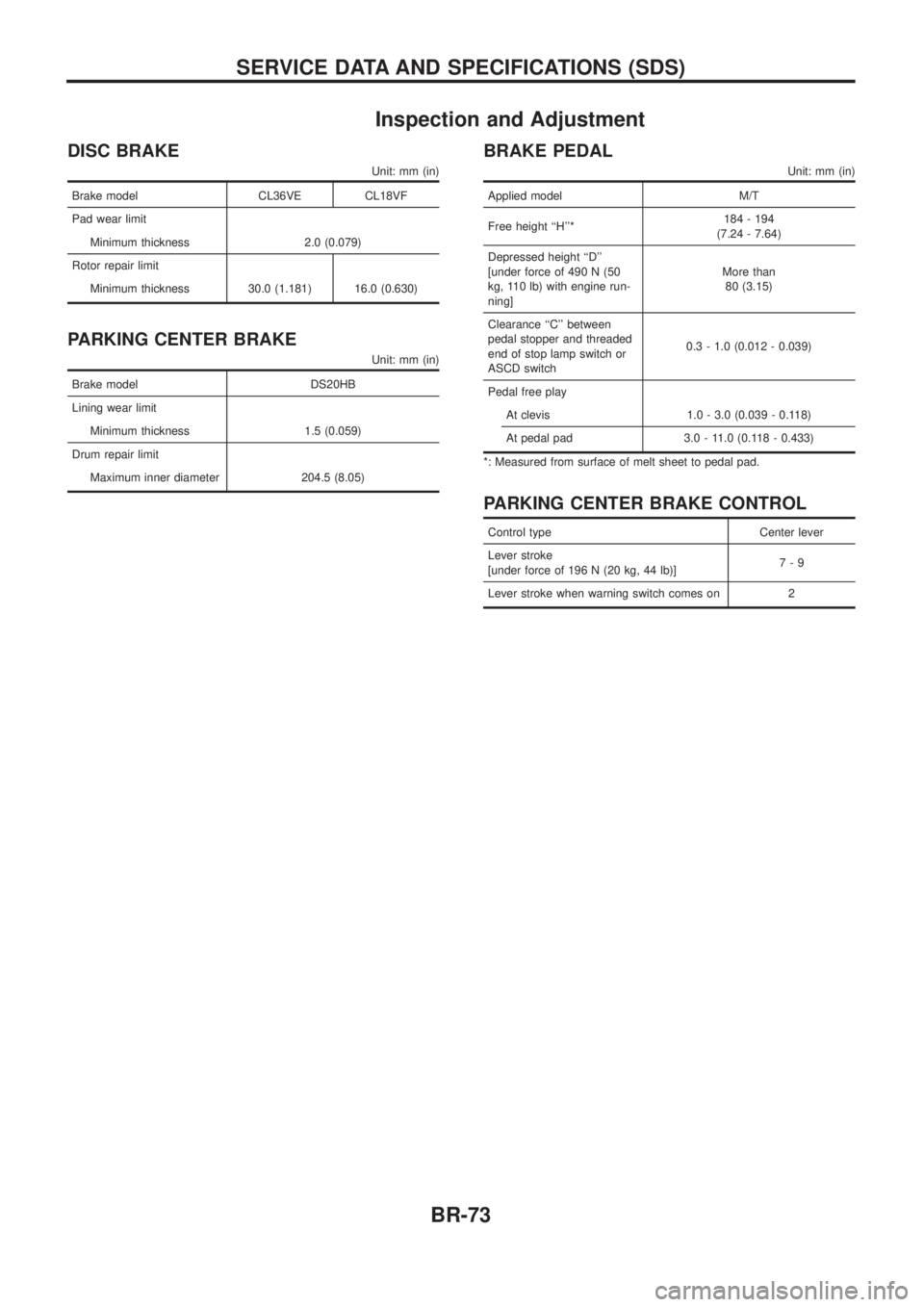
DISC BRAKE
Unit: mm (in)
Brake model CL36VE CL18VF
Pad wear limit
Minimum thickness 2.0 (0.079)
Rotor repair limit
Minimum thickness 30.0 (1.181) 16.0 (0.630)
PARKING CENTER BRAKE
Unit: mm (in)
Brake model DS20HB
Lining wear limit
Minimum thickness 1.5 (0.059)
Drum repair limit
Maximum inner diameter 204.5 (8.05)
BRAKE PEDAL
Unit: mm (in)
Applied model M/T
Free height ``H''*184 - 194
(7.24 - 7.64)
Depressed height ``D''
[under force of 490 N (50
kg, 110 lb) with engine run-
ning]More than
80 (3.15)
Clearance ``C'' between
pedal stopper and threaded
end of stop lamp switch or
ASCD switch0.3 - 1.0 (0.012 - 0.039)
Pedal free play
At clevis 1.0 - 3.0 (0.039 - 0.118)
At pedal pad 3.0 - 11.0 (0.118 - 0.433)
*: Measured from surface of melt sheet to pedal pad.
PARKING CENTER BRAKE CONTROL
Control type Center lever
Lever stroke
[under force of 196 N (20 kg, 44 lb)]7-9
Lever stroke when warning switch comes on 2
SERVICE DATA AND SPECIFICATIONS (SDS)
BR-73
Page 102 of 1226
Back Door Trim
REMOVAL Ð Back door trim
V1Remove bolts securing pull handle (LH only).
V2Remove inside handle escutcheon (LH only).
V3Remove clip securing high-mounted stop lamp cover (RH only).
V4Remove back door cover (RH only).
V5Remove clips securing back door upper garnish.
V6Remove clips securing back door trim.
V7Pull out back door trim.
SBT533
INTERIOR TRIM
BT-24
Page 106 of 1226
V7Drip molding
V8Drip weatherstrip
V9High-mounted stop lamp
V10Side guard molding
V11Rear combination lamp
Rear combination lamps are installed with bolts.
V12Back door weatherstrip
SBT572
SBT539
SBT545
SBT544
SBT543
EXTERIOR
BT-28
Page 181 of 1226

DTC and MIL Detection Logic
When a malfunction is detected for the ®rst time, the malfunction (DTC) is stored in the ECM memory.
The MIL will light up each time the ECM detects malfunction. However, if the same malfunction is experienced
in two consecutive driving patterns and the engine is still running, the MIL will stay lit up. For diagnostic items
causing the MIL to light up, refer to ``DIAGNOSTIC TROUBLE CODE INDEX'', EC-1.
Diagnostic Trouble Code (DTC)
HOW TO READ DTC
The diagnostic trouble code can be read by the following methods.
1. The number of blinks of the malfunction indicator lamp in the Diagnostic Test Mode II (Self-Diagnostic
Results) Examples: 11, 13, 14, etc.
These DTCs are controlled by NISSAN.
2. CONSULT Examples: ``CAM POS SEN (PUMP)'', etc.
+Output of the trouble code means that the indicated circuit has a malfunction. However, in the Mode
II it does not indicate whether the malfunction is still occurring or occurred in the past and returned
to normal.
CONSULT can identify them. Therefore, using CONSULT (if available) is recommended.
HOW TO ERASE DTC
The diagnostic trouble code can be erased by the following methods.
Selecting ``ERASE'' in the ``SELF-DIAG RESULTS'' mode with CONSULT.
Changing the diagnostic test mode from Diagnostic Test Mode II to Mode I. (Refer to EC-32.)
+If the battery terminal is disconnected, the diagnostic trouble code will be lost within 24 hours.
+When you erase the DTC, using CONSULT is easier and quicker than switching the diagnostic test
modes.
HOW TO ERASE DTC (With CONSULT)
1. If the ignition switch stays ``ON'' after repair work, be sure to turn ignition switch ``OFF'' once. Wait at least
5 seconds and then turn it ``ON'' (Engine stopped) again.
2. Turn CONSULT ``ON'' and touch ``ENGINE''.
3. Touch ``SELF-DIAG RESULTS''.
4. Touch ``ERASE''. (The DTC in the ECM will be erased.)
HOW TO ERASE DTC (No Tools)
1. If the ignition switch stays ``ON'' after repair work, be sure to turn ignition switch ``OFF'' once. Wait at least
5 seconds and then turn it ``ON'' again.
2. Change the diagnostic test mode from Mode II to Mode I. (Refer to EC-32.)
SEF691S
ON BOARD DIAGNOSTIC SYSTEM DESCRIPTION
EC-30
Page 182 of 1226
Malfunction Indicator Lamp (MIL)
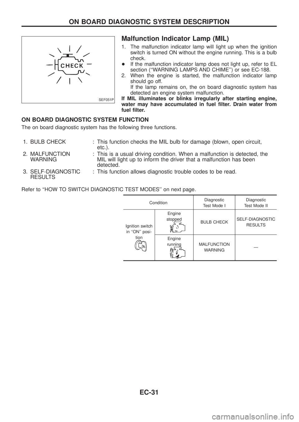
1. The malfunction indicator lamp will light up when the ignition
switch is turned ON without the engine running. This is a bulb
check.
+If the malfunction indicator lamp does not light up, refer to EL
section (``WARNING LAMPS AND CHIME'') or see EC-188.
2. When the engine is started, the malfunction indicator lamp
should go off.
If the lamp remains on, the on board diagnostic system has
detected an engine system malfunction.
If MIL illuminates or blinks irregularly after starting engine,
water may have accumulated in fuel ®lter. Drain water from
fuel ®lter.
ON BOARD DIAGNOSTIC SYSTEM FUNCTION
The on board diagnostic system has the following three functions.
1. BULB CHECK : This function checks the MIL bulb for damage (blown, open circuit,
etc.).
2. MALFUNCTION
WARNING: This is a usual driving condition. When a malfunction is detected, the
MIL will light up to inform the driver that a malfunction has been
detected.
3. SELF-DIAGNOSTIC
RESULTS: This function allows diagnostic trouble codes to be read.
Refer to ``HOW TO SWITCH DIAGNOSTIC TEST MODES'' on next page.
ConditionDiagnostic
Test Mode IDiagnostic
Test Mode II
Ignition switch
in ``ON'' posi-
tion
Engine
stopped
BULB CHECKSELF-DIAGNOSTIC
RESULTS
Engine
running
MALFUNCTION
WARNINGÐ
SEF051P
ON BOARD DIAGNOSTIC SYSTEM DESCRIPTION
EC-31
Page 186 of 1226
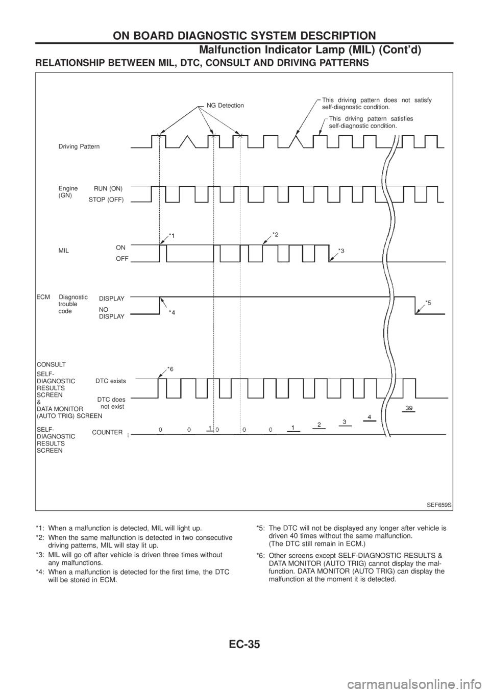
RELATIONSHIP BETWEEN MIL, DTC, CONSULT AND DRIVING PATTERNS
*1: When a malfunction is detected, MIL will light up.
*2: When the same malfunction is detected in two consecutive
driving patterns, MIL will stay lit up.
*3: MIL will go off after vehicle is driven three times without
any malfunctions.
*4: When a malfunction is detected for the ®rst time, the DTC
will be stored in ECM.*5: The DTC will not be displayed any longer after vehicle is
driven 40 times without the same malfunction.
(The DTC still remain in ECM.)
*6: Other screens except SELF-DIAGNOSTIC RESULTS &
DATA MONITOR (AUTO TRIG) cannot display the mal-
function. DATA MONITOR (AUTO TRIG) can display the
malfunction at the moment it is detected.
SEF659S
RUN (ON)
STOP (OFF)
ON
OFF
DISPLAY
NO
DISPLAY
DTC exists
DTC does
not exist
COUNTER Driving Pattern
Engine
(GN)
MIL
ECM Diagnostic
trouble
code
CONSULT
SELF-
DIAGNOSTIC
RESULTS
SCREEN
&
DATA MONITOR
(AUTO TRIG) SCREEN
SELF-
DIAGNOSTIC
RESULTS
SCREENNG DetectionThis driving pattern does not satisfy
self-diagnostic condition.
This driving pattern satis®es
self-diagnostic condition.
ON BOARD DIAGNOSTIC SYSTEM DESCRIPTION
Malfunction Indicator Lamp (MIL) (Cont'd)
EC-35
Page 194 of 1226
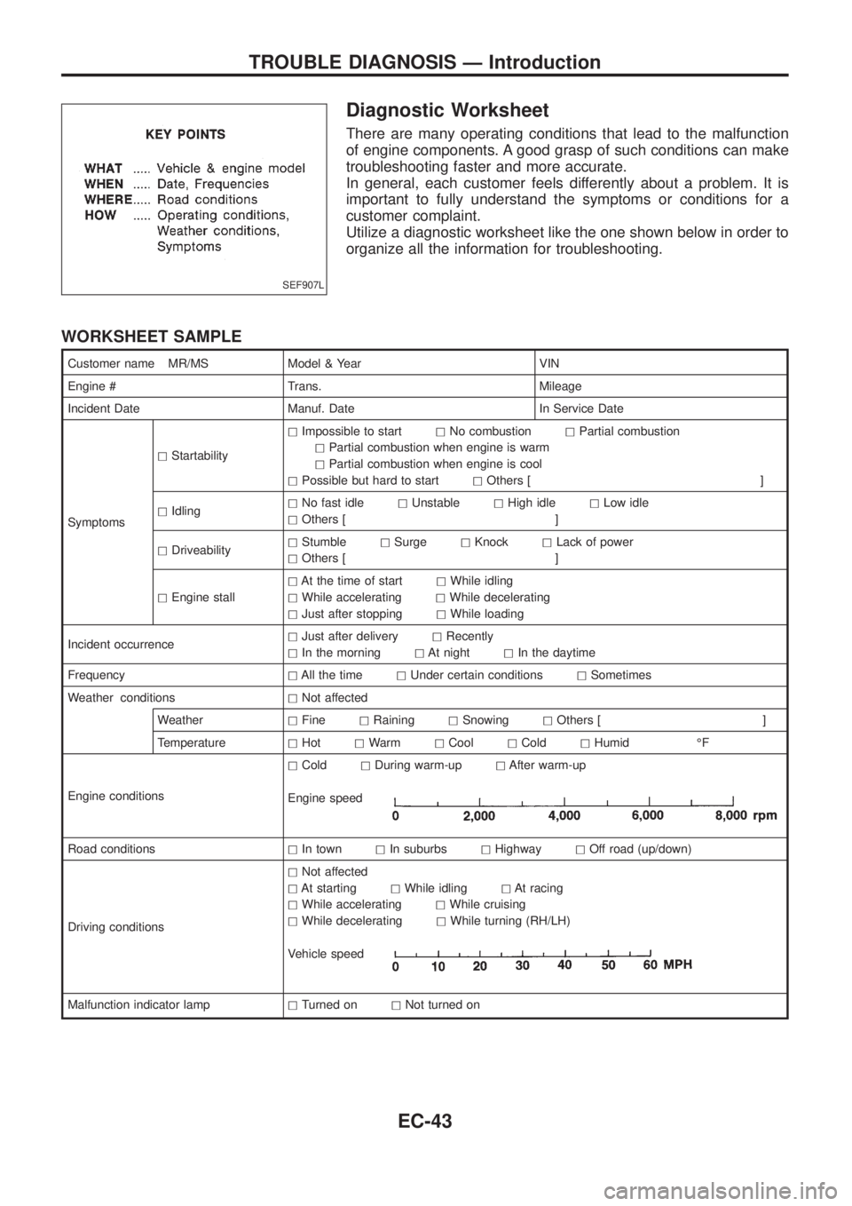
Diagnostic Worksheet
There are many operating conditions that lead to the malfunction
of engine components. A good grasp of such conditions can make
troubleshooting faster and more accurate.
In general, each customer feels differently about a problem. It is
important to fully understand the symptoms or conditions for a
customer complaint.
Utilize a diagnostic worksheet like the one shown below in order to
organize all the information for troubleshooting.
WORKSHEET SAMPLE
Customer name MR/MS Model & Year VIN
Engine # Trans. Mileage
Incident Date Manuf. Date In Service Date
SymptomshStartabilityhImpossible to starthNo combustionhPartial combustion
hPartial combustion when engine is warm
hPartial combustion when engine is cool
hPossible but hard to starthOthers [ ]
hIdlinghNo fast idlehUnstablehHigh idlehLow idle
hOthers [ ]
hDriveabilityhStumblehSurgehKnockhLack of power
hOthers [ ]
hEngine stallhAt the time of starthWhile idling
hWhile acceleratinghWhile decelerating
hJust after stoppinghWhile loading
Incident occurrencehJust after deliveryhRecently
hIn the morninghAt nighthIn the daytime
FrequencyhAll the timehUnder certain conditionshSometimes
Weather conditionshNot affected
WeatherhFinehRaininghSnowinghOthers [ ]
TemperaturehHothWarmhCoolhColdhHumid ÉF
Engine conditionshColdhDuring warm-uphAfter warm-up
Engine speed
Road conditionshIn townhIn suburbshHighwayhOff road (up/down)
Driving conditionshNot affected
hAt startinghWhile idlinghAt racing
hWhile acceleratinghWhile cruising
hWhile deceleratinghWhile turning (RH/LH)
Vehicle speed
Malfunction indicator lamphTurned onhNot turned on
SEF907L
TROUBLE DIAGNOSIS Ð Introduction
EC-43