Page 738 of 1226
Front Axle and Front Suspension Parts
Check front axle and front suspension parts for excessive play,
cracks, wear and other damage.
+Shake each front wheel to check for excessive play.
+Make sure that cotter pin is inserted.
+Retighten all axle and suspensions nuts and bolts to the speci-
®ed torque.
Tightening torque:
Refer to FRONT SUSPENSION (FA-24).
+Check front axle and front suspension parts for wear, cracks
and other damage.
+Check shock absorber for oil leakage and other damage.
+Check knuckle ¯ange for grease leakage and knuckle ¯ange
grease seal for cracks and other damage.
Front Wheel Bearing
+Check that wheel bearings operate smoothly.
+Check axial end play.
Axial end play:
0mm(0in)
+Adjust wheel bearing preload if there is any axial end play or
wheel bearing does not turn smoothly.
SMA525A
SFA851B
SFA852B
SFA413A
ON-VEHICLE SERVICE
FA-5
Page 742 of 1226

TOE-IN
Measure toe-in using the following procedure.
WARNING:
+Always perform the following procedure on a ¯at surface.
+Make sure that no person is in front of the vehicle before
pushing it.
1. Bounce front of vehicle up and down to stabilize the posture.
2. Push the vehicle straight ahead about 5 m (16 ft).
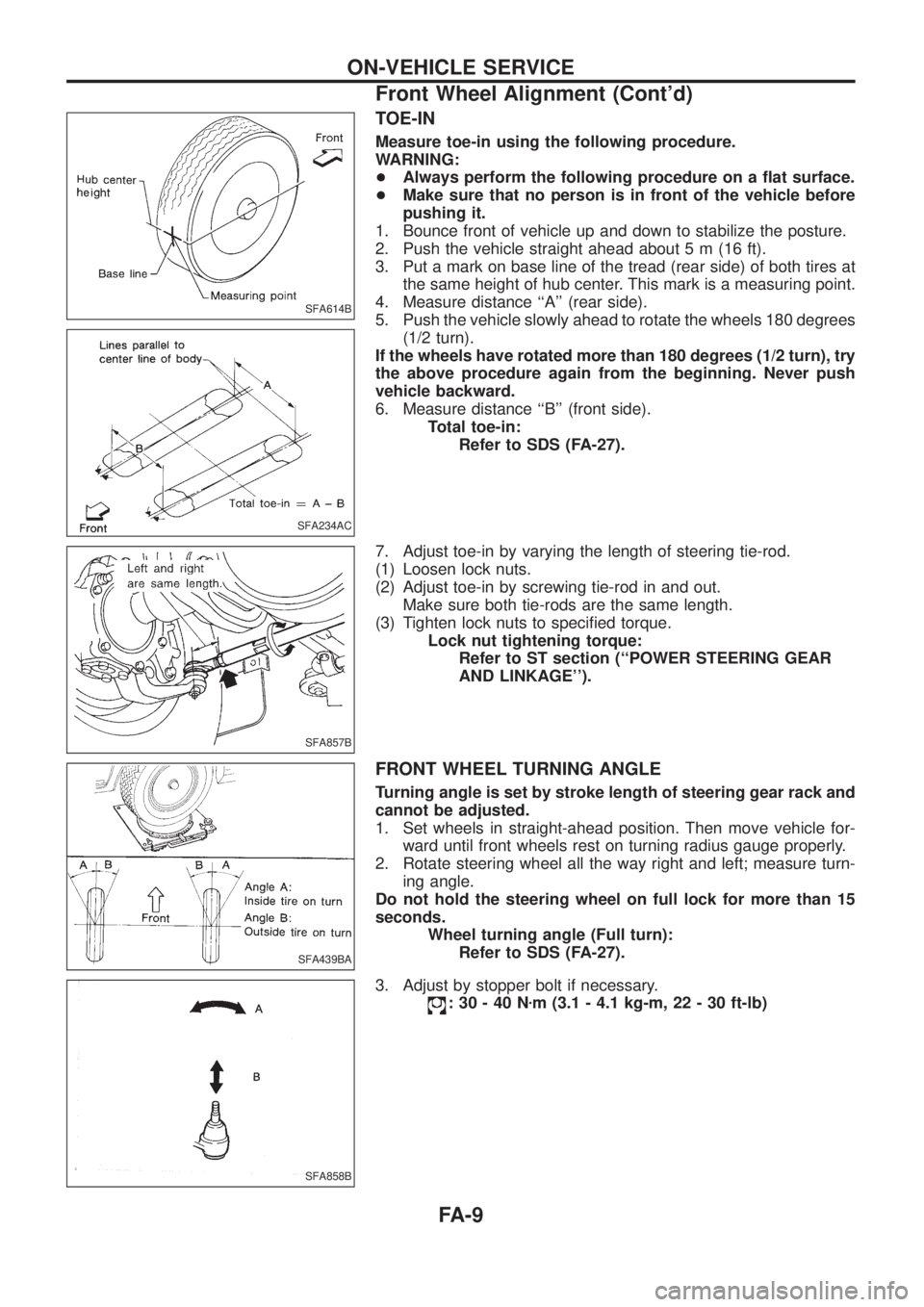
3. Put a mark on base line of the tread (rear side) of both tires at
the same height of hub center. This mark is a measuring point.
4. Measure distance ``A'' (rear side).
5. Push the vehicle slowly ahead to rotate the wheels 180 degrees
(1/2 turn).
If the wheels have rotated more than 180 degrees (1/2 turn), try
the above procedure again from the beginning. Never push
vehicle backward.
6. Measure distance ``B'' (front side).
Total toe-in:
Refer to SDS (FA-27).
7. Adjust toe-in by varying the length of steering tie-rod.
(1) Loosen lock nuts.
(2) Adjust toe-in by screwing tie-rod in and out.
Make sure both tie-rods are the same length.
(3) Tighten lock nuts to speci®ed torque.
Lock nut tightening torque:
Refer to ST section (``POWER STEERING GEAR
AND LINKAGE'').
FRONT WHEEL TURNING ANGLE
Turning angle is set by stroke length of steering gear rack and
cannot be adjusted.
1. Set wheels in straight-ahead position. Then move vehicle for-
ward until front wheels rest on turning radius gauge properly.
2. Rotate steering wheel all the way right and left; measure turn-
ing angle.
Do not hold the steering wheel on full lock for more than 15
seconds.
Wheel turning angle (Full turn):
Refer to SDS (FA-27).
3. Adjust by stopper bolt if necessary.
:30-40Nzm (3.1 - 4.1 kg-m, 22 - 30 ft-lb)
SFA614B
SFA234AC
SFA857B
SFA439BA
SFA858B
ON-VEHICLE SERVICE
Front Wheel Alignment (Cont'd)
FA-9
Page 761 of 1226

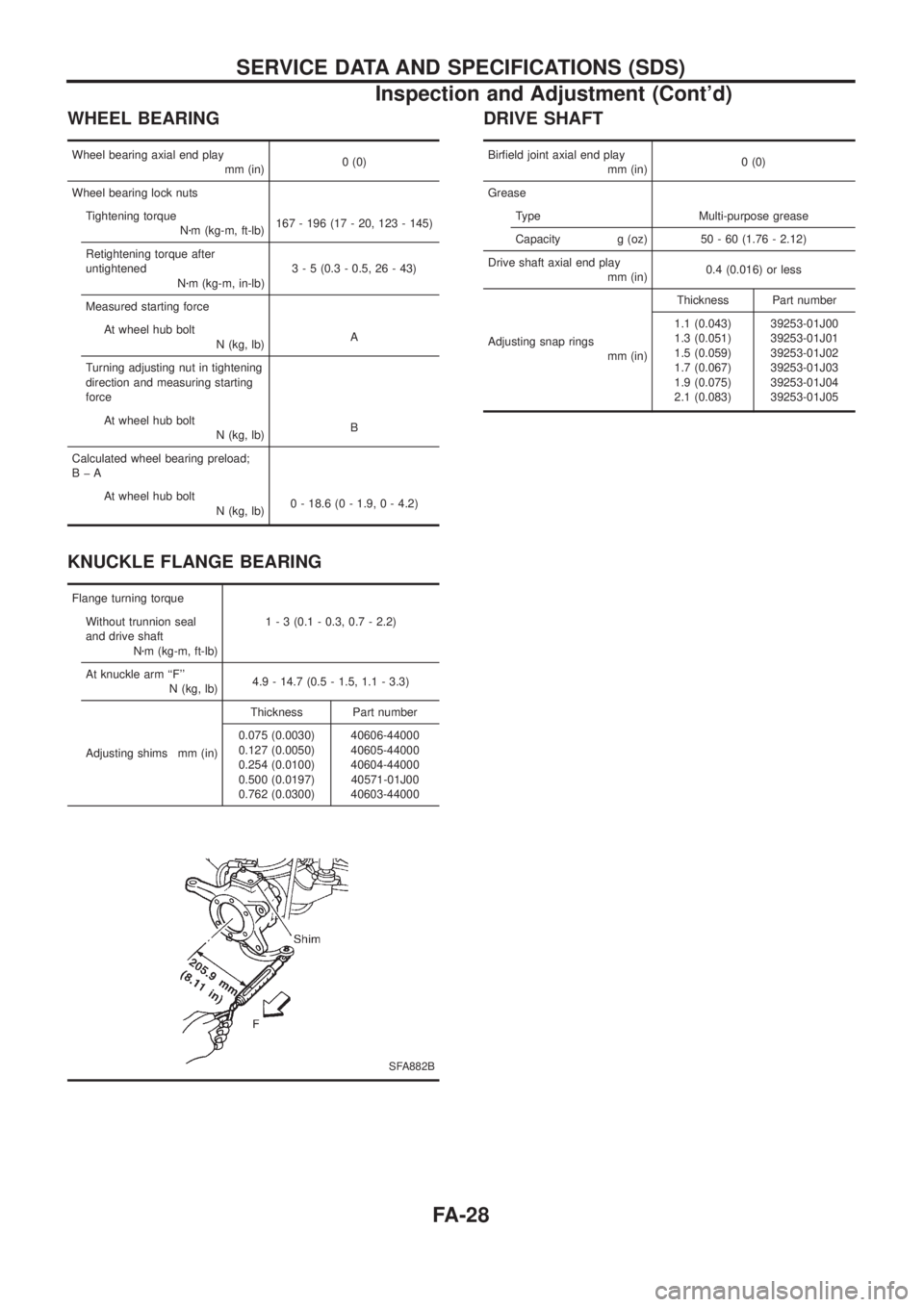
WHEEL BEARING
Wheel bearing axial end play
mm (in)0 (0)
Wheel bearing lock nuts
Tightening torque
Nzm (kg-m, ft-lb)167 - 196 (17 - 20, 123 - 145)
Retightening torque after
untightened
Nzm (kg-m, in-lb)3 - 5 (0.3 - 0.5, 26 - 43)
Measured starting force
At wheel hub bolt
N (kg, lb)A
Turning adjusting nut in tightening
direction and measuring starting
force
At wheel hub bolt
N (kg, lb)B
Calculated wheel bearing preload;
BþA
At wheel hub bolt
N (kg, lb)0 - 18.6 (0 - 1.9, 0 - 4.2)
KNUCKLE FLANGE BEARING
Flange turning torque
Without trunnion seal
and drive shaft
Nzm (kg-m, ft-lb)1 - 3 (0.1 - 0.3, 0.7 - 2.2)
At knuckle arm ``F''
N (kg, lb)4.9 - 14.7 (0.5 - 1.5, 1.1 - 3.3)
Adjusting shims mm (in)Thickness Part number
0.075 (0.0030)
0.127 (0.0050)
0.254 (0.0100)
0.500 (0.0197)
0.762 (0.0300)40606-44000
40605-44000
40604-44000
40571-01J00
40603-44000
SFA882B
DRIVE SHAFT
Bir®eld joint axial end play
mm (in)0 (0)
Grease
Type Multi-purpose grease
Capacity g (oz) 50 - 60 (1.76 - 2.12)
Drive shaft axial end play
mm (in)0.4 (0.016) or less
Adjusting snap rings
mm (in)Thickness Part number
1.1 (0.043)
1.3 (0.051)
1.5 (0.059)
1.7 (0.067)
1.9 (0.075)
2.1 (0.083)39253-01J00
39253-01J01
39253-01J02
39253-01J03
39253-01J04
39253-01J05
SERVICE DATA AND SPECIFICATIONS (SDS)
Inspection and Adjustment (Cont'd)
FA-28
Page 1000 of 1226

Repacking Front Wheel Bearing and Axle Joint
Grease
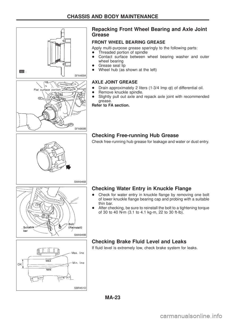
FRONT WHEEL BEARING GREASE
Apply multi-purpose grease sparingly to the following parts:
+Threaded portion of spindle
+Contact surface between wheel bearing washer and outer
wheel bearing
+Grease seal lip
+Wheel hub (as shown at the left)
AXLE JOINT GREASE
+Drain approximately 2 liters (1-3/4 Imp qt) of differential oil.
+Remove knuckle spindle.
+Slightly pull out axle and repack axle joint with recommended
grease.
Refer to FA section.
Checking Free-running Hub Grease
Check free-running hub grease for leakage and water or dust entry.
Checking Water Entry in Knuckle Flange
+Check for water entry in knuckle ¯ange by removing one bolt
of lower knuckle ¯ange bearing cap and probing with a suitable
thin bar.
+After checking, be sure to reinstall the bolt to a tightening torque
of 30 to 40 Nzm (3.1 to 4.1 kg-m, 22 to 30 ft-lb).
Checking Brake Fluid Level and Leaks
If ¯uid level is extremely low, check brake system for leaks.
SFA469A
SFA869B
SMA946B
SMA949B
SBR451D
CHASSIS AND BODY MAINTENANCE
MA-23
Page 1101 of 1226
Rear Axle and Rear Suspension Parts
Check rear axle and rear suspension parts for excessive play, wear
or damage.
+Shake each rear wheel to check for excessive play.
+Retighten all nuts and bolts to the speci®ed torque.
Tightening torque:
Refer to REAR SUSPENSION, RA-12.
+Check shock absorber for oil leakage or other damage.
+Check shock absorber bushing for excessive wear or other
damage.
Rear Wheel Bearing
+Check that wheel bearings operate smoothly.
+Check axial end play.
Axial end play:
0mm(0in)
SMA525A
SRA814A
SRA755A
ON-VEHICLE SERVICE
RA-5
Page 1106 of 1226
6. Install a new wheel bearing lock washer.
7. Tighten wheel bearing lock nut to speci®ed torque.
: 441 - 490 Nzm (45 - 50 kg-m, 325 - 362 ft-lb)
Be sure to bend bearing lock washer up.
8. Check wheel bearing preload.
a. Turn bearing cage (with respect to axle shaft) two or three
times. It must turn smoothly.
b. Attach spring gauge to bearing cage bolt (as shown at left) and
pull it at a speed of 10 rpm to measure preload.
Spring gauge indication:
8.8 - 42.2 N (0.9 - 4.3 kg, 2.0 - 9.5 lb)
9. Install new oil seal to rear axle housing using a suitable tool.
After installing new oil seal, coat sealing lip with multi-purpose
grease.
10. Install new O-ring to rear axle housing.
11. Press ABS sensor rotor onto axle shaft until it contacts wheel
bearing lock nut.
12. Install axle shafts in rear axle housing.
Be careful not to damage oil seal.
SRA828A
SRA821A
SRA850A
SRA822A
SRA823A
REAR AXLE
Installation (Cont'd)
RA-10