2006 NISSAN PATROL sunroof
[x] Cancel search: sunroofPage 78 of 1226

BODY & TRIM
SECTION
BT
CONTENTS
PRECAUTIONS ...............................................................1
Service Notice..............................................................1
Supplemental Restraint System (SRS) ``AIR
BAG''and``SEATBELTPRE-TENSIONER''...............1
GENERAL SERVICING ...................................................2
Clip and Fastener ........................................................2
BODY END ......................................................................4
Body Front End............................................................4
Body Rear End and Opener ........................................6
DOOR ........................................................................\
.......9
Front Door....................................................................9
Rear Door ..................................................................10
INSTRUMENT PANEL ................................................... 11
INTERIOR TRIM ............................................................14
Side and Floor Trim ...................................................14
Door Trim ...................................................................18
Roof Trim ...................................................................20
Back Door Trim ..........................................................24 EXTERIOR
.....................................................................26
SEAT ........................................................................\
......32
Front Seat ..................................................................32
Heated Seat ...............................................................34
Rear Seat...................................................................35
3rd Seat .....................................................................37
SUNROOF ......................................................................39
WINDSHIELD AND WINDOWS ....................................42
Windshield .................................................................43
Rear Side Window .....................................................44
Back Door Window ....................................................45
MIRROR ........................................................................\
.46
Door Mirror.................................................................46
CAB BODY ....................................................................47
Body Mounting ...........................................................48
BODY ALIGNMENT .......................................................49
Engine Compartment .................................................49
Underbody .................................................................51
. For seat belt, refer to MA and RS section.
. For wiring diagrams of body electrical systems, refer to EL section.
BT
Page 105 of 1226
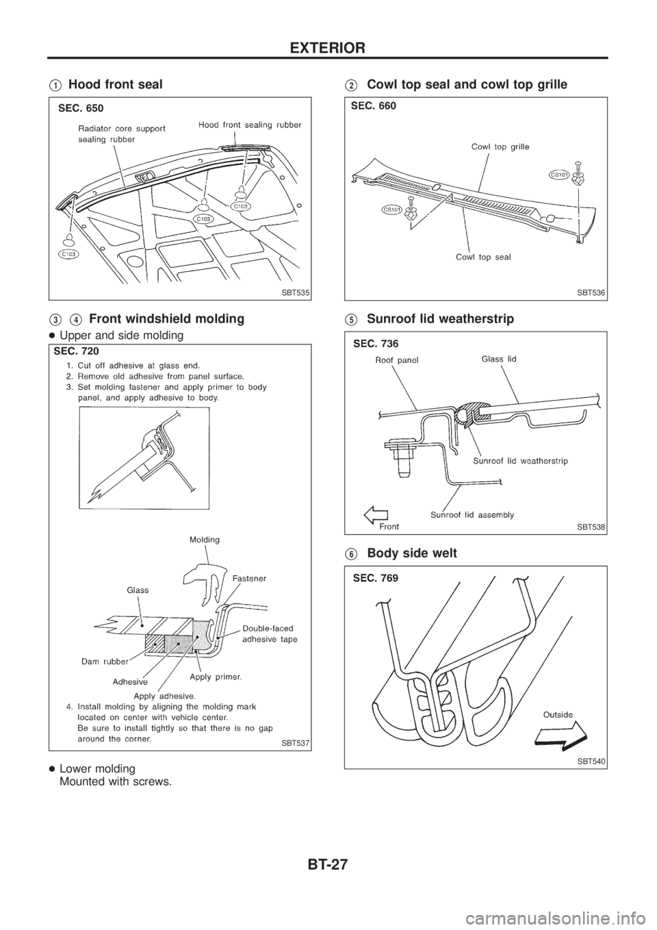
V1Hood front seal
V3V4Front windshield molding
+Upper and side molding
+Lower molding
Mounted with screws.
V2Cowl top seal and cowl top grille
V5Sunroof lid weatherstrip
V6Body side welt
SBT535
SBT537
SBT536
SBT538
SBT540
EXTERIOR
BT-27
Page 117 of 1226
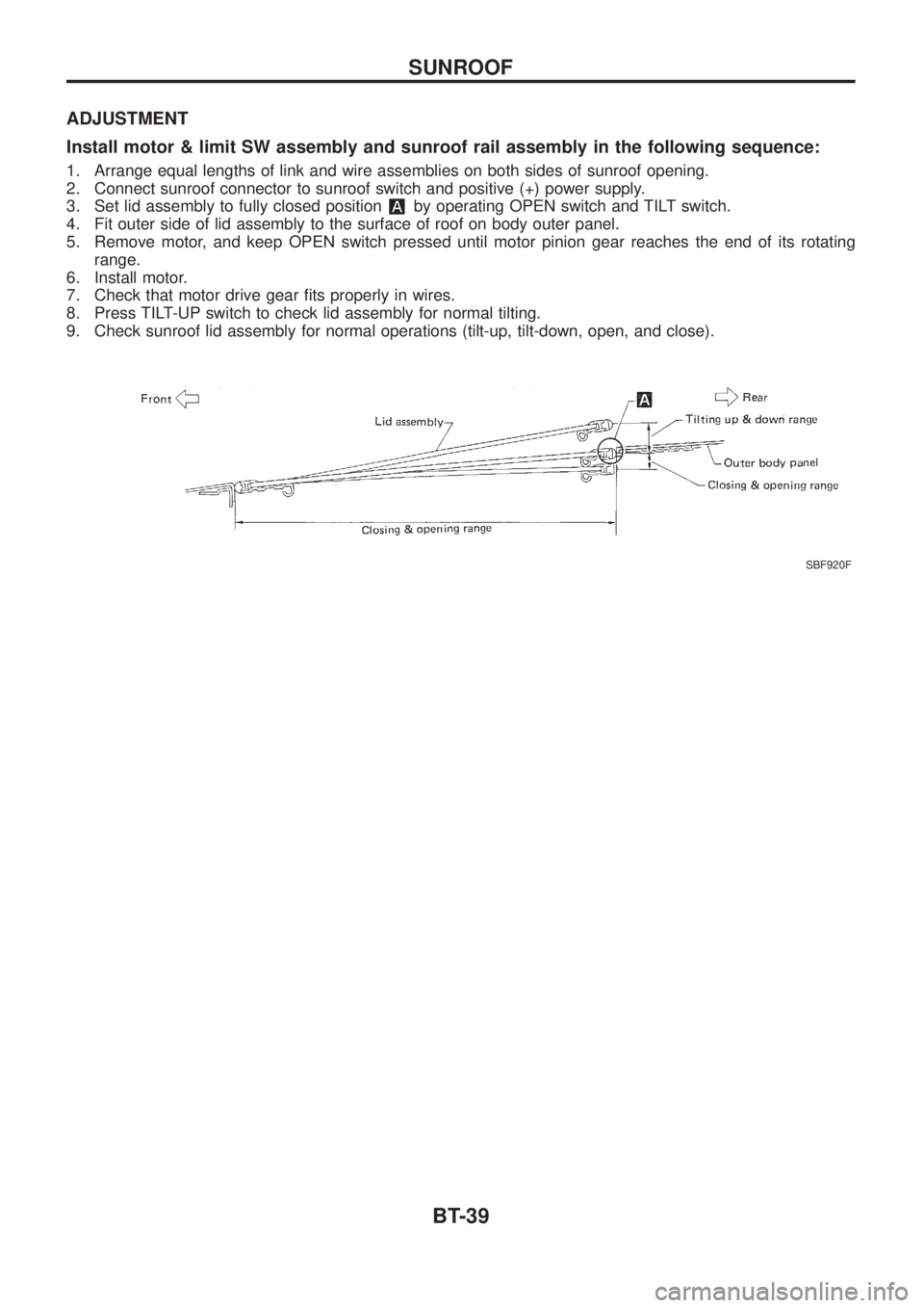
ADJUSTMENT
Install motor & limit SW assembly and sunroof rail assembly in the following sequence:
1. Arrange equal lengths of link and wire assemblies on both sides of sunroof opening.
2. Connect sunroof connector to sunroof switch and positive (+) power supply.
3. Set lid assembly to fully closed position
by operating OPEN switch and TILT switch.
4. Fit outer side of lid assembly to the surface of roof on body outer panel.
5. Remove motor, and keep OPEN switch pressed until motor pinion gear reaches the end of its rotating
range.
6. Install motor.
7. Check that motor drive gear ®ts properly in wires.
8. Press TILT-UP switch to check lid assembly for normal tilting.
9. Check sunroof lid assembly for normal operations (tilt-up, tilt-down, open, and close).
SBF920F
SUNROOF
BT-39
Page 118 of 1226
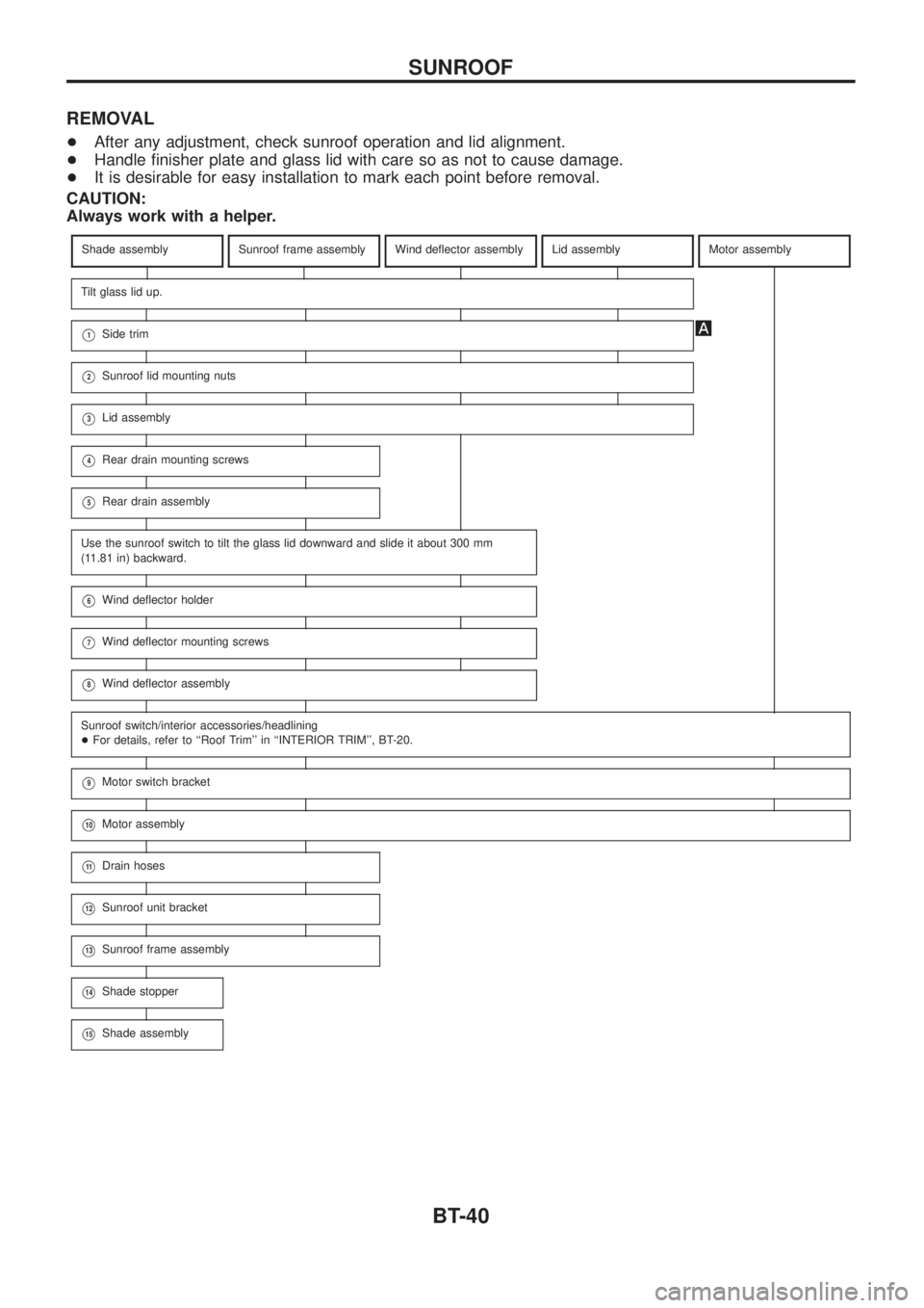
REMOVAL
+After any adjustment, check sunroof operation and lid alignment.
+Handle ®nisher plate and glass lid with care so as not to cause damage.
+It is desirable for easy installation to mark each point before removal.
CAUTION:
Always work with a helper.
Shade assemblySunroof frame assemblyWind de¯ector assemblyLid assemblyMotor assembly
Tilt glass lid up.
V1Side trim
V2Sunroof lid mounting nuts
V3Lid assembly
V4Rear drain mounting screws
V5Rear drain assembly
Use the sunroof switch to tilt the glass lid downward and slide it about 300 mm
(11.81 in) backward.
V6Wind de¯ector holder
V7Wind de¯ector mounting screws
V8Wind de¯ector assembly
Sunroof switch/interior accessories/headlining
+For details, refer to ``Roof Trim'' in ``INTERIOR TRIM'', BT-20.
V9Motor switch bracket
V10Motor assembly
V11Drain hoses
V12Sunroof unit bracket
V13Sunroof frame assembly
V14Shade stopper
V15Shade assembly
SUNROOF
BT-40
Page 119 of 1226
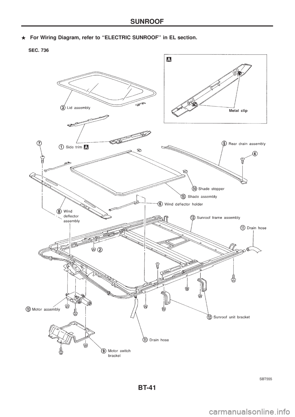
.For Wiring Diagram, refer to ``ELECTRIC SUNROOF'' in EL section.
SBT555
SUNROOF
BT-41
Page 344 of 1226
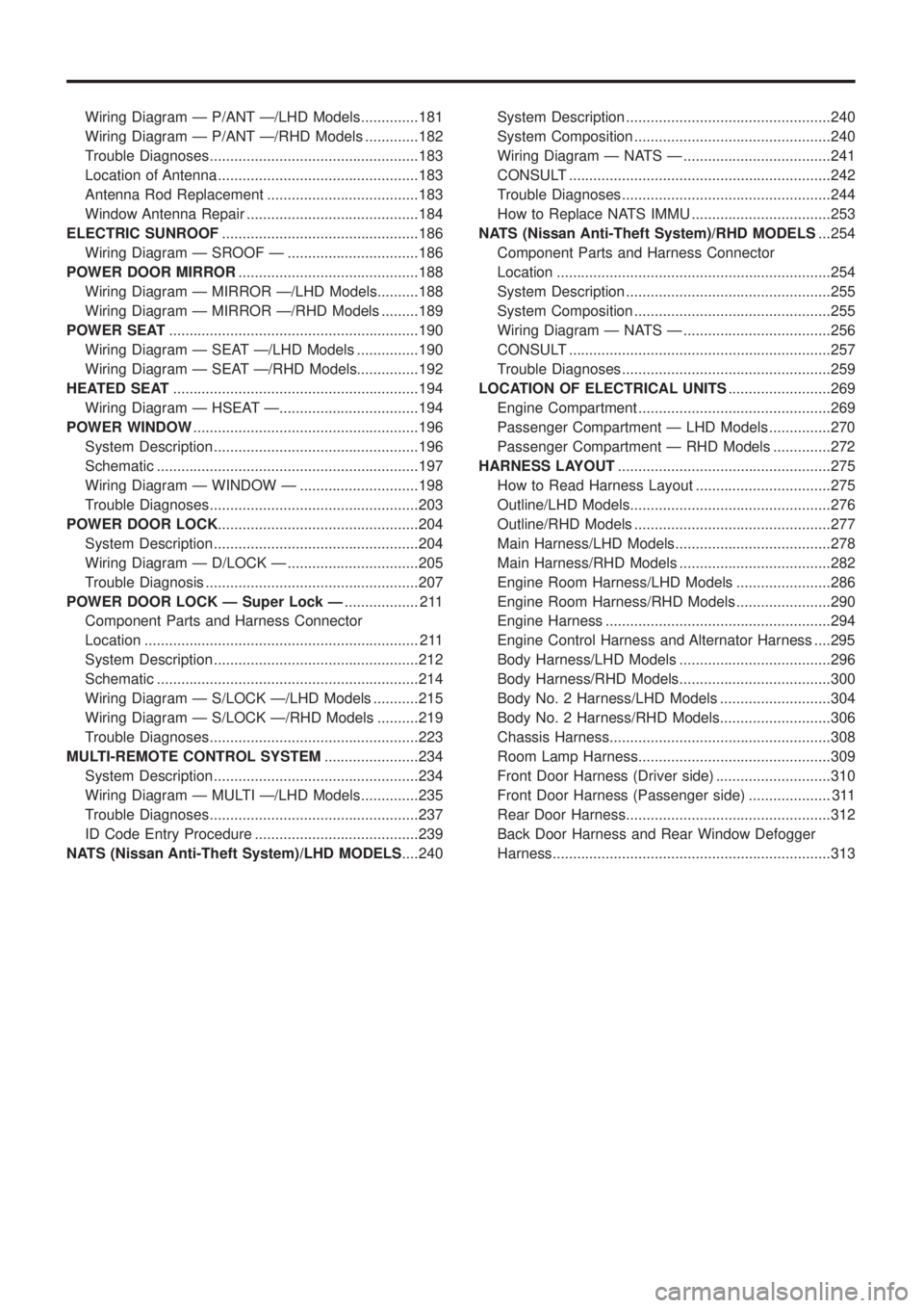
Wiring Diagram Ð P/ANT Ð/LHD Models..............181
Wiring Diagram Ð P/ANT Ð/RHD Models .............182
Trouble Diagnoses...................................................183
Location of Antenna .................................................183
Antenna Rod Replacement .....................................183
Window Antenna Repair ..........................................184
ELECTRIC SUNROOF................................................186
Wiring Diagram Ð SROOF Ð ................................186
POWER DOOR MIRROR............................................188
Wiring Diagram Ð MIRROR Ð/LHD Models..........188
Wiring Diagram Ð MIRROR Ð/RHD Models .........189
POWER SEAT.............................................................190
Wiring Diagram Ð SEAT Ð/LHD Models ...............190
Wiring Diagram Ð SEAT Ð/RHD Models...............192
HEATED SEAT............................................................194
Wiring Diagram Ð HSEAT Ð..................................194
POWER WINDOW.......................................................196
System Description ..................................................196
Schematic ................................................................197
Wiring Diagram Ð WINDOW Ð .............................198
Trouble Diagnoses...................................................203
POWER DOOR LOCK.................................................204
System Description ..................................................204
Wiring Diagram Ð D/LOCK Ð ................................205
Trouble Diagnosis ....................................................207
POWER DOOR LOCK Ð Super Lock Ð.................. 211
Component Parts and Harness Connector
Location ................................................................... 211
System Description ..................................................212
Schematic ................................................................214
Wiring Diagram Ð S/LOCK Ð/LHD Models ...........215
Wiring Diagram Ð S/LOCK Ð/RHD Models ..........219
Trouble Diagnoses...................................................223
MULTI-REMOTE CONTROL SYSTEM.......................234
System Description ..................................................234
Wiring Diagram Ð MULTI Ð/LHD Models..............235
Trouble Diagnoses...................................................237
ID Code Entry Procedure ........................................239
NATS (Nissan Anti-Theft System)/LHD MODELS....240System Description ..................................................240
System Composition ................................................240
Wiring Diagram Ð NATS Ð ....................................241
CONSULT ................................................................242
Trouble Diagnoses...................................................244
How to Replace NATS IMMU ..................................253
NATS (Nissan Anti-Theft System)/RHD MODELS...254
Component Parts and Harness Connector
Location ...................................................................254
System Description ..................................................255
System Composition ................................................255
Wiring Diagram Ð NATS Ð ....................................256
CONSULT ................................................................257
Trouble Diagnoses...................................................259
LOCATION OF ELECTRICAL UNITS.........................269
Engine Compartment ...............................................269
Passenger Compartment Ð LHD Models ...............270
Passenger Compartment Ð RHD Models ..............272
HARNESS LAYOUT....................................................275
How to Read Harness Layout .................................275
Outline/LHD Models.................................................276
Outline/RHD Models ................................................277
Main Harness/LHD Models......................................278
Main Harness/RHD Models .....................................282
Engine Room Harness/LHD Models .......................286
Engine Room Harness/RHD Models .......................290
Engine Harness .......................................................294
Engine Control Harness and Alternator Harness ....295
Body Harness/LHD Models .....................................296
Body Harness/RHD Models.....................................300
Body No. 2 Harness/LHD Models ...........................304
Body No. 2 Harness/RHD Models...........................306
Chassis Harness......................................................308
Room Lamp Harness...............................................309
Front Door Harness (Driver side) ............................310
Front Door Harness (Passenger side) .................... 311
Rear Door Harness..................................................312
Back Door Harness and Rear Window Defogger
Harness....................................................................313
Page 531 of 1226
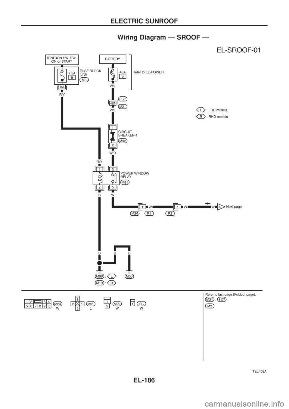
Wiring Diagram Ð SROOF Ð
TEL458A
ELECTRIC SUNROOF
EL-186
Page 532 of 1226
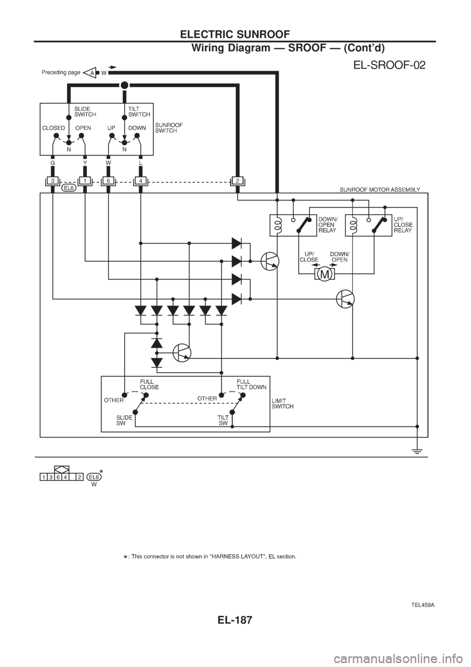
TEL459A
ELECTRIC SUNROOF
Wiring Diagram Ð SROOF Ð (Cont'd)
EL-187