2006 NISSAN PATROL drain bolt
[x] Cancel search: drain boltPage 10 of 1226
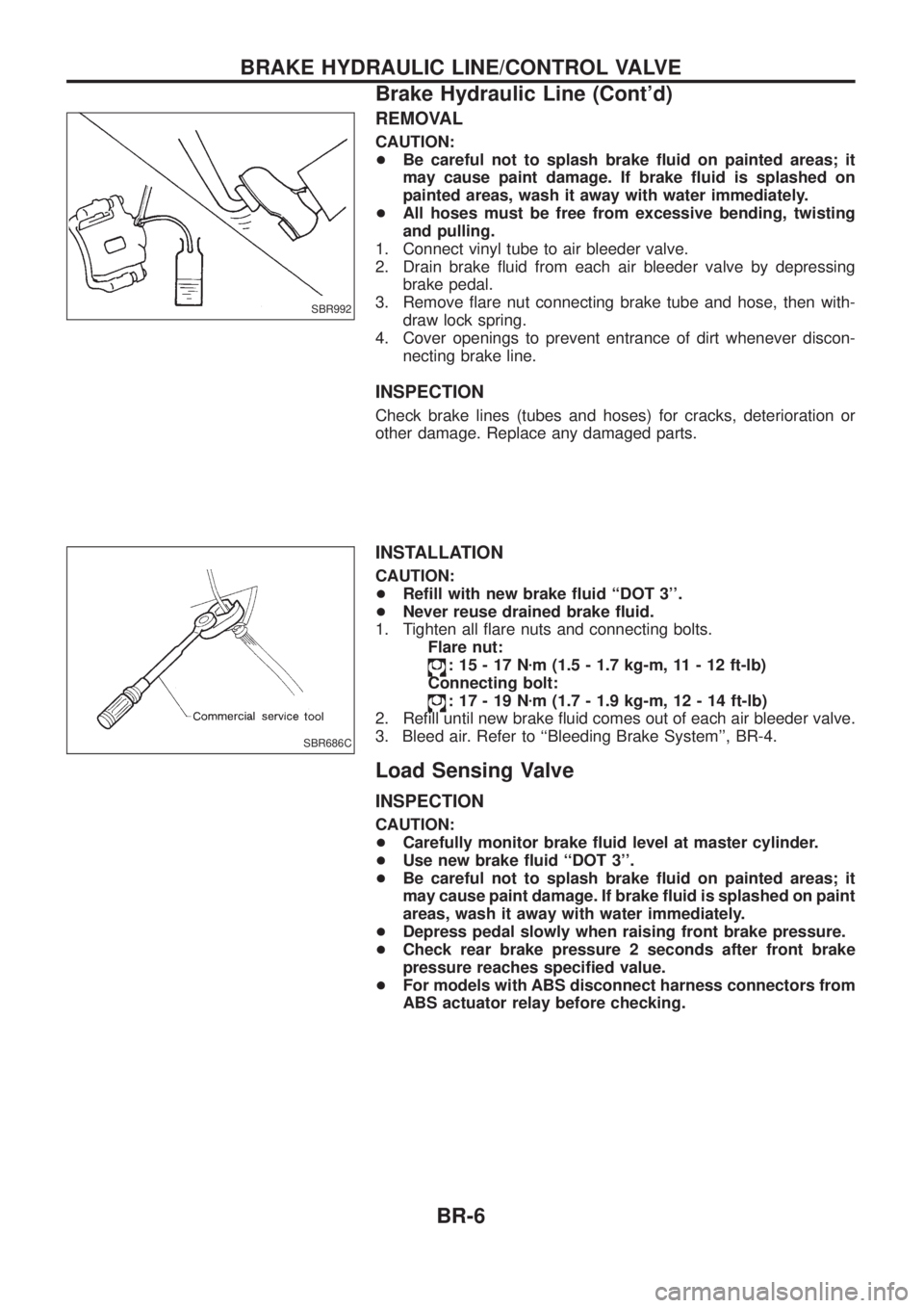
REMOVAL
CAUTION:
+Be careful not to splash brake ¯uid on painted areas; it
may cause paint damage. If brake ¯uid is splashed on
painted areas, wash it away with water immediately.
+ All hoses must be free from excessive bending, twisting
and pulling.
1. Connect vinyl tube to air bleeder valve.
2. Drain brake ¯uid from each air bleeder valve by depressing brake pedal.
3. Remove ¯are nut connecting brake tube and hose, then with- draw lock spring.
4. Cover openings to prevent entrance of dirt whenever discon- necting brake line.
INSPECTION
Check brake lines (tubes and hoses) for cracks, deterioration or
other damage. Replace any damaged parts.
INSTALLATION
CAUTION:
+Re®ll with new brake ¯uid ``DOT 3''.
+ Never reuse drained brake ¯uid.
1. Tighten all ¯are nuts and connecting bolts. Flare nut:
:15-17N zm (1.5 - 1.7 kg-m, 11 - 12 ft-lb)
Connecting bolt:
:17-19N zm (1.7 - 1.9 kg-m, 12 - 14 ft-lb)
2. Re®ll until new brake ¯uid comes out of each air bleeder valve.
3. Bleed air. Refer to ``Bleeding Brake System'', BR-4.
Load Sensing Valve
INSPECTION
CAUTION:
+ Carefully monitor brake ¯uid level at master cylinder.
+ Use new brake ¯uid ``DOT 3''.
+ Be careful not to splash brake ¯uid on painted areas; it
may cause paint damage. If brake ¯uid is splashed on paint
areas, wash it away with water immediately.
+ Depress pedal slowly when raising front brake pressure.
+ Check rear brake pressure 2 seconds after front brake
pressure reaches speci®ed value.
+ For models with ABS disconnect harness connectors from
ABS actuator relay before checking.
SBR992
SBR686C
BRAKE HYDRAULIC LINE/CONTROL VALVE
Brake Hydraulic Line (Cont'd)
BR-6
Page 19 of 1226

Brake Booster
ON-VEHICLE SERVICE
Operating check
+Depress brake pedal several times with engine off. After
exhausting vacuum, make sure there is no change in pedal
stroke.
+ Depress brake pedal, then start engine. If pedal goes down
slightly, operation is normal.
Airtight check
+Start engine, and stop it after one or two minutes. Depress
brake pedal several times slowly. Booster is airtight if pedal
stroke is less each time.
+ Depress brake pedal while engine is running, and stop engine
with pedal depressed. The pedal stroke should not change after
holding pedal down for 30 seconds.
REMOVAL
CAUTION:
+Be careful not to splash brake ¯uid on painted areas; it
may cause paint damage. If brake ¯uid is splashed on
painted areas, wash it away with water immediately.
+ Be careful not to deform or bend brake pipes, during
removal of booster.
INSPECTION
Output rod length check
1. Apply vacuum of þ66.7 kPa (þ500 mmHg, þ19.69 inHg) to
brake booster with a hand vacuum pump.
2. Check output rod length. Speci®ed length:10.275 - 10.525 mm (0.4045 - 0.4144 in)
INSTALLATION
CAUTION:
+Be careful not to deform or bend brake pipes during instal-
lation of booster.
+ Replace clevis pin if damaged.
+ Re®ll with new brake ¯uid ``DOT 3''.
+ Never reuse drained brake ¯uid.
+ Take care not to damage brake booster mounting bolt
thread when installing. Due to the narrow angle of
installation, the threads can be damaged by the dash
panel.
SBR002A
SBR365AA
SBR170E
SBR281A
SBR116BF
BRAKE BOOSTER
BR-15
Page 28 of 1226
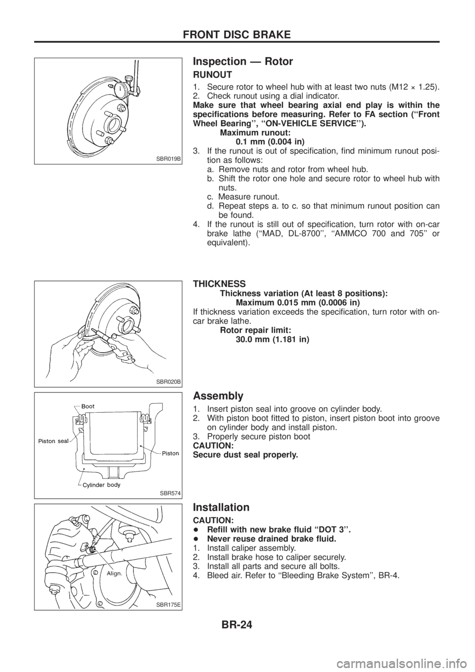
Inspection Ð Rotor
RUNOUT
1. Secure rotor to wheel hub with at least two nuts (M12 ý 1.25).
2. Check runout using a dial indicator.
Make sure that wheel bearing axial end play is within the
speci®cations before measuring. Refer to FA section (``Front
Wheel Bearing'', ``ON-VEHICLE SERVICE'').Maximum runout:0.1 mm (0.004 in)
3. If the runout is out of speci®cation, ®nd minimum runout posi- tion as follows:
a. Remove nuts and rotor from wheel hub.
b. Shift the rotor one hole and secure rotor to wheel hub withnuts.
c. Measure runout.
d. Repeat steps a. to c. so that minimum runout position can be found.
4. If the runout is still out of speci®cation, turn rotor with on-car brake lathe (``MAD, DL-8700'', ``AMMCO 700 and 705'' or
equivalent).
THICKNESS
Thickness variation (At least 8 positions): Maximum 0.015 mm (0.0006 in)
If thickness variation exceeds the speci®cation, turn rotor with on-
car brake lathe. Rotor repair limit:30.0 mm (1.181 in)
Assembly
1. Insert piston seal into groove on cylinder body.
2. With piston boot ®tted to piston, insert piston boot into grooveon cylinder body and install piston.
3. Properly secure piston boot
CAUTION:
Secure dust seal properly.
Installation
CAUTION:
+ Re®ll with new brake ¯uid ``DOT 3''.
+ Never reuse drained brake ¯uid.
1. Install caliper assembly.
2. Install brake hose to caliper securely.
3. Install all parts and secure all bolts.
4. Bleed air. Refer to ``Bleeding Brake System'', BR-4.
SBR019B
SBR020B
SBR574
SBR175E
FRONT DISC BRAKE
BR-24
Page 32 of 1226
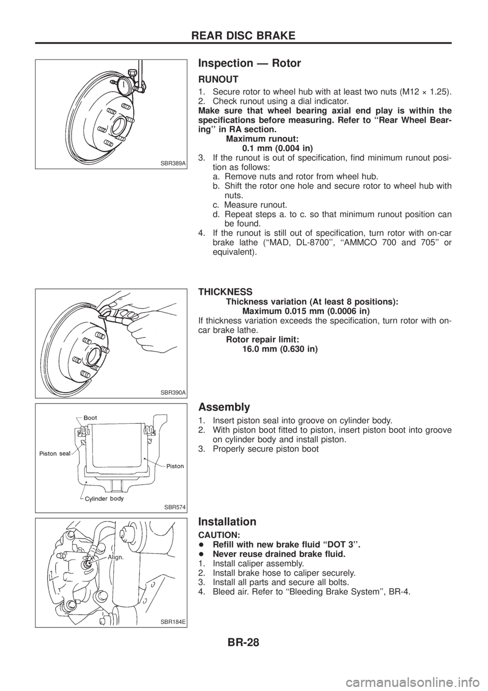
Inspection Ð Rotor
RUNOUT
1. Secure rotor to wheel hub with at least two nuts (M12 ý 1.25).
2. Check runout using a dial indicator.
Make sure that wheel bearing axial end play is within the
speci®cations before measuring. Refer to ``Rear Wheel Bear-
ing'' in RA section.Maximum runout:0.1 mm (0.004 in)
3. If the runout is out of speci®cation, ®nd minimum runout posi- tion as follows:
a. Remove nuts and rotor from wheel hub.
b. Shift the rotor one hole and secure rotor to wheel hub withnuts.
c. Measure runout.
d. Repeat steps a. to c. so that minimum runout position can be found.
4. If the runout is still out of speci®cation, turn rotor with on-car brake lathe (``MAD, DL-8700'', ``AMMCO 700 and 705'' or
equivalent).
THICKNESS
Thickness variation (At least 8 positions): Maximum 0.015 mm (0.0006 in)
If thickness variation exceeds the speci®cation, turn rotor with on-
car brake lathe. Rotor repair limit:16.0 mm (0.630 in)
Assembly
1. Insert piston seal into groove on cylinder body.
2. With piston boot ®tted to piston, insert piston boot into grooveon cylinder body and install piston.
3. Properly secure piston boot
Installation
CAUTION:
+ Re®ll with new brake ¯uid ``DOT 3''.
+ Never reuse drained brake ¯uid.
1. Install caliper assembly.
2. Install brake hose to caliper securely.
3. Install all parts and secure all bolts.
4. Bleed air. Refer to ``Bleeding Brake System'', BR-4.
SBR389A
SBR390A
SBR574
SBR184E
REAR DISC BRAKE
BR-28
Page 42 of 1226
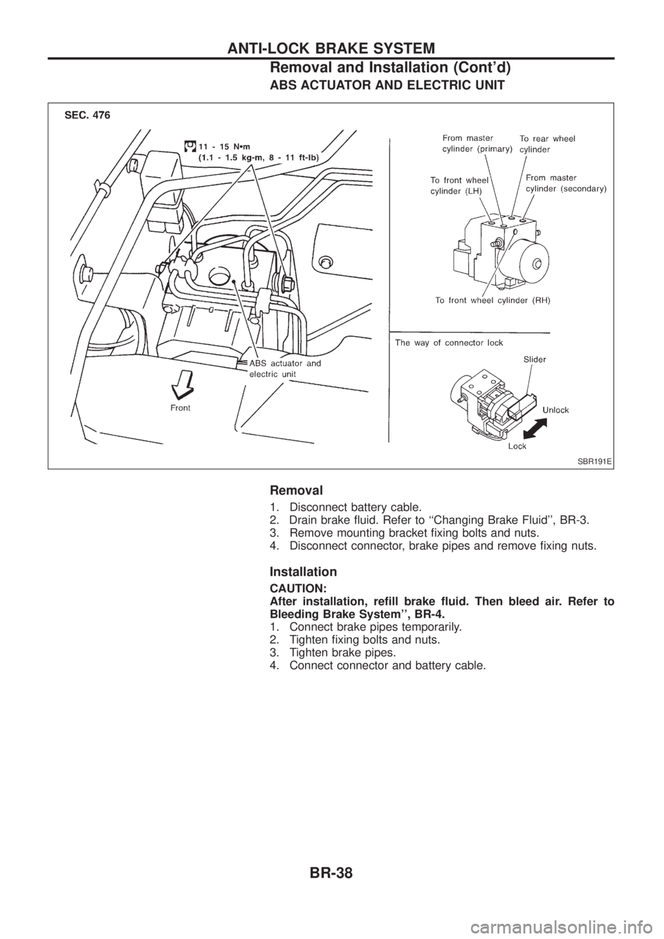
ABS ACTUATOR AND ELECTRIC UNIT
Removal
1. Disconnect battery cable.
2. Drain brake ¯uid. Refer to ``Changing Brake Fluid'', BR-3.
3. Remove mounting bracket ®xing bolts and nuts.
4. Disconnect connector, brake pipes and remove ®xing nuts.
Installation
CAUTION:
After installation, re®ll brake ¯uid. Then bleed air. Refer to
Bleeding Brake System'', BR-4.
1. Connect brake pipes temporarily.
2. Tighten ®xing bolts and nuts.
3. Tighten brake pipes.
4. Connect connector and battery cable.
SBR191E
ANTI-LOCK BRAKE SYSTEM
Removal and Installation (Cont'd)BR-38
Page 157 of 1226
Precautions
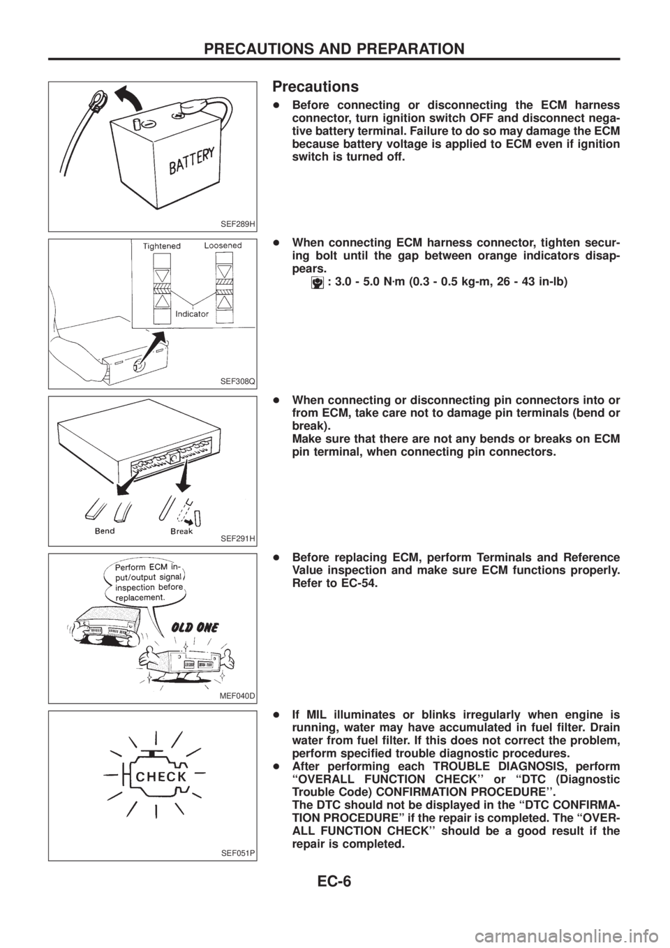
+Before connecting or disconnecting the ECM harness
connector, turn ignition switch OFF and disconnect nega-
tive battery terminal. Failure to do so may damage the ECM
because battery voltage is applied to ECM even if ignition
switch is turned off.
+When connecting ECM harness connector, tighten secur-
ing bolt until the gap between orange indicators disap-
pears.
: 3.0 - 5.0 Nzm (0.3 - 0.5 kg-m, 26 - 43 in-lb)
+When connecting or disconnecting pin connectors into or
from ECM, take care not to damage pin terminals (bend or
break).
Make sure that there are not any bends or breaks on ECM
pin terminal, when connecting pin connectors.
+Before replacing ECM, perform Terminals and Reference
Value inspection and make sure ECM functions properly.
Refer to EC-54.
+If MIL illuminates or blinks irregularly when engine is
running, water may have accumulated in fuel ®lter. Drain
water from fuel ®lter. If this does not correct the problem,
perform speci®ed trouble diagnostic procedures.
+After performing each TROUBLE DIAGNOSIS, perform
``OVERALL FUNCTION CHECK'' or ``DTC (Diagnostic
Trouble Code) CONFIRMATION PROCEDURE''.
The DTC should not be displayed in the ``DTC CONFIRMA-
TION PROCEDUREº if the repair is completed. The ``OVER-
ALL FUNCTION CHECK'' should be a good result if the
repair is completed.
SEF289H
SEF308Q
SEF291H
MEF040D
SEF051P
PRECAUTIONS AND PREPARATION
EC-6
Page 198 of 1226
jA
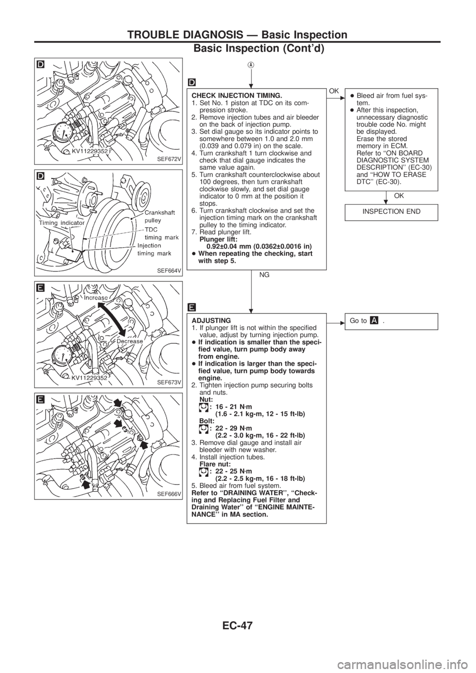
CHECK INJECTION TIMING.
1. Set No. 1 piston at TDC on its com-
pression stroke.
2. Remove injection tubes and air bleeder
on the back of injection pump.
3. Set dial gauge so its indicator points to
somewhere between 1.0 and 2.0 mm
(0.039 and 0.079 in) on the scale.
4. Turn crankshaft 1 turn clockwise and
check that dial gauge indicates the
same value again.
5. Turn crankshaft counterclockwise about
100 degrees, then turn crankshaft
clockwise slowly, and set dial gauge
indicator to 0 mm at the position it
stops.
6. Turn crankshaft clockwise and set the
injection timing mark on the crankshaft
pulley to the timing indicator.
7. Read plunger lift.
Plunger lift:
0.92 0.04 mm (0.0362 0.0016 in)
+When repeating the checking, start
with step 5.
NG
cOK
+Bleed air from fuel sys-
tem.
+After this inspection,
unnecessary diagnostic
trouble code No. might
be displayed.
Erase the stored
memory in ECM.
Refer to ``ON BOARD
DIAGNOSTIC SYSTEM
DESCRIPTION'' (EC-30)
and ``HOW TO ERASE
DTC'' (EC-30).
OK
INSPECTION END
ADJUSTING
1. If plunger lift is not within the speci®ed
value, adjust by turning injection pump.
+If indication is smaller than the speci-
®ed value, turn pump body away
from engine.
+If indication is larger than the speci-
®ed value, turn pump body towards
engine.
2. Tighten injection pump securing bolts
and nuts.
Nut:
: 16-21Nzm
(1.6 - 2.1 kg-m, 12 - 15 ft-lb)
Bolt:
: 22-29Nzm
(2.2 - 3.0 kg-m, 16 - 22 ft-lb)
3. Remove dial gauge and install air
bleeder with new washer.
4. Install injection tubes.
Flare nut:
: 22-25Nzm
(2.2 - 2.5 kg-m, 16 - 18 ft-lb)
5. Bleed air from fuel system.
Refer to ``DRAINING WATER'', ``Check-
ing and Replacing Fuel Filter and
Draining Water'' of ``ENGINE MAINTE-
NANCE'' in MA section.
cGo to.
SEF672V
SEF664V
SEF673V
SEF666V
.
.
.
TROUBLE DIAGNOSIS Ð Basic Inspection
Basic Inspection (Cont'd)
EC-47
Page 698 of 1226
CAUTION:
+When installing sliding parts such as camshaft and oil
seal, be sure to apply new engine oil on their sliding sur-
faces.
+When tightening cylinder head bolts, apply new engine oil
to thread portions and seat surfaces of bolts.
Removal
1. Remove charge air cooler assembly.
2. Set No. 1 cylinder at BDC on its expansion stroke.
3. Drain engine coolant from drain plugs on cylinder block and
radiator.
4. Remove air cleaner and/or air duct.
5. Remove timing belt.
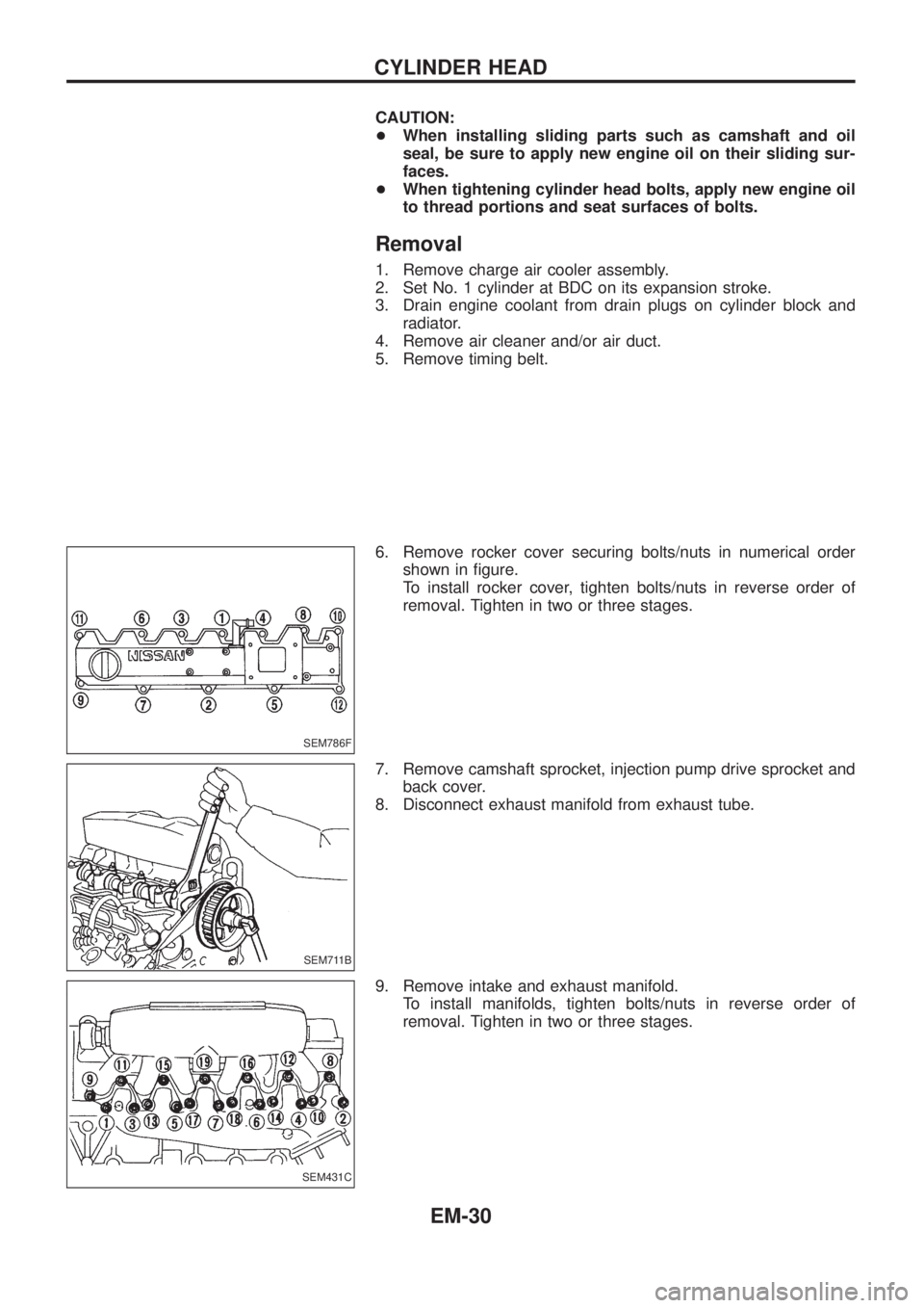
6. Remove rocker cover securing bolts/nuts in numerical order
shown in ®gure.
To install rocker cover, tighten bolts/nuts in reverse order of
removal. Tighten in two or three stages.
7. Remove camshaft sprocket, injection pump drive sprocket and
back cover.
8. Disconnect exhaust manifold from exhaust tube.
9. Remove intake and exhaust manifold.
To install manifolds, tighten bolts/nuts in reverse order of
removal. Tighten in two or three stages.
SEM786F
SEM711B
SEM431C
CYLINDER HEAD
EM-30