Page 713 of 1226
Removal
1. Remove engine, transmission and transfer's undercovers, oil
pan guard and hood.
2. Drain engine coolant.
3. Remove charge air cooler assembly.
4. Remove vacuum hoses, fuel tubes, harnesses, and connectors
and so on.
5. Remove radiator assembly.
6. Remove drive belts.
7. Remove power steering oil pump, alternator and air conditioner
compressor.
8. Remove starter motor assembly.
9. Remove front exhaust tube.
10. Remove transmission from vehicle.
Refer to MT section.
11. Hoist engine with engine slingers and remove engine mounting
bolts from both sides.
12. Remove engine from vehicle.
Installation
+Install in reverse order of removal.
ENGINE REMOVAL
EM-45
Page 715 of 1226

CAUTION:
+When installing sliding parts such as bearings and
pistons, apply engine oil to the sliding surfaces.
+Place removed parts, such as bearings and bearing caps,
in their proper order and direction.
+When installing connecting rod bolts and main bearing cap
bolts, apply new engine oil to threads and seating surfaces
of nuts.
+Do not allow any magnetic materials to contact the ring
gear teeth of drive plate.
Disassembly
PISTON AND CRANKSHAFT
1. Place engine on a work stand.
2. Remove timing belt and injection pump.
3. Drain coolant and remove water pump.
4. Remove front cover.
5. Drain oil.
6. Remove oil pan and oil pump.
7. Remove cylinder head.
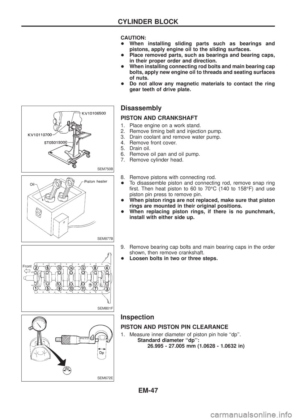
8. Remove pistons with connecting rod.
+To disassemble piston and connecting rod, remove snap ring
®rst. Then heat piston to 60 to 70ÉC (140 to 158ÉF) and use
piston pin press to remove pin.
+When piston rings are not replaced, make sure that piston
rings are mounted in their original positions.
+When replacing piston rings, if there is no punchmark,
install with either side up.
9. Remove bearing cap bolts and main bearing caps in the order
shown, then remove crankshaft.
+Loosen bolts in two or three steps.
Inspection
PISTON AND PISTON PIN CLEARANCE
1. Measure inner diameter of piston pin hole ``dp''.
Standard diameter ``dp'':
26.995 - 27.005 mm (1.0628 - 1.0632 in)
SEM750B
SEM877B
SEM801F
SEM672E
CYLINDER BLOCK
EM-47
Page 963 of 1226
When installing oil jet, align oil jet's boss with hole on cylin-
der block.
Oil jet bolt:
:30-40Nzm (3.1 - 4.1 kg-m, 22 - 30 ft-lb)
Turbocharger
+Before removing water tube, drain coolant ®rst.
+Be careful not to deform tubes.
+After installation, run engine for a few minutes, and check
for oil leakage.
SLC975
SLC197B
ENGINE LUBRICATION SYSTEM
Oil Jet (Cont'd)
LC-8
Page 1000 of 1226

Repacking Front Wheel Bearing and Axle Joint
Grease
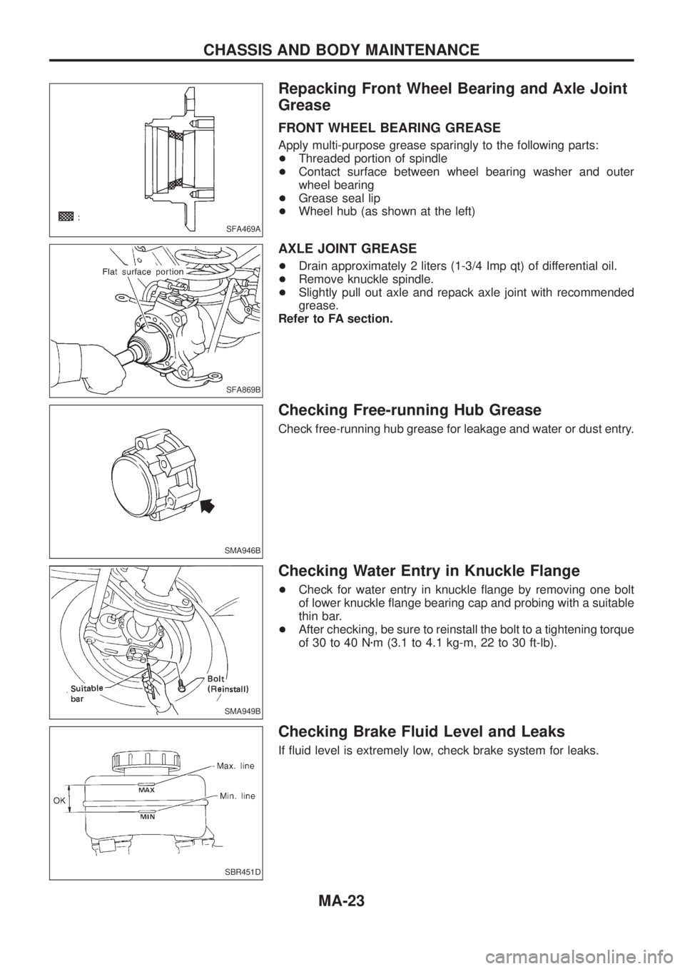
FRONT WHEEL BEARING GREASE
Apply multi-purpose grease sparingly to the following parts:
+Threaded portion of spindle
+Contact surface between wheel bearing washer and outer
wheel bearing
+Grease seal lip
+Wheel hub (as shown at the left)
AXLE JOINT GREASE
+Drain approximately 2 liters (1-3/4 Imp qt) of differential oil.
+Remove knuckle spindle.
+Slightly pull out axle and repack axle joint with recommended
grease.
Refer to FA section.
Checking Free-running Hub Grease
Check free-running hub grease for leakage and water or dust entry.
Checking Water Entry in Knuckle Flange
+Check for water entry in knuckle ¯ange by removing one bolt
of lower knuckle ¯ange bearing cap and probing with a suitable
thin bar.
+After checking, be sure to reinstall the bolt to a tightening torque
of 30 to 40 Nzm (3.1 to 4.1 kg-m, 22 to 30 ft-lb).
Checking Brake Fluid Level and Leaks
If ¯uid level is extremely low, check brake system for leaks.
SFA469A
SFA869B
SMA946B
SMA949B
SBR451D
CHASSIS AND BODY MAINTENANCE
MA-23
Page 1201 of 1226
Removal
1. Drain ¯uid and oil from transfer and transmission (M/T model
only).
2. Remove exhaust front and rear tubes. Refer to FE section
(``EXHAUST SYSTEM'').
3. Remove front and rear propeller shaft. Refer to PD section
(``Removal and Installation'', ``PROPELLER SHAFT'').
4. Disconnect neutral position switch and 4WD switch harness
connectors.
5. Remove transfer control lever from transfer cross shaft.
6. Remove transfer from transmission.
WARNING:
Support transfer while removing it.
Installation
+Apply recommended sealant to mating surface to transmission.
(M/T models only)
Recommended sealant:
Genuine anaerobic liquid gasket, Three Bond
TB1215, Loctite Part No. 51813 or equivalent
+Tighten transfer bolts.
Transfer ®xing bolts:
:32-42Nzm (3.3 - 4.3 kg-m, 24 - 31 ft-lb)
SMT251D
SMT268D
SMT176BA
REMOVAL AND INSTALLATION
TF-8