2006 NISSAN PATROL power steering fluid
[x] Cancel search: power steering fluidPage 780 of 1226
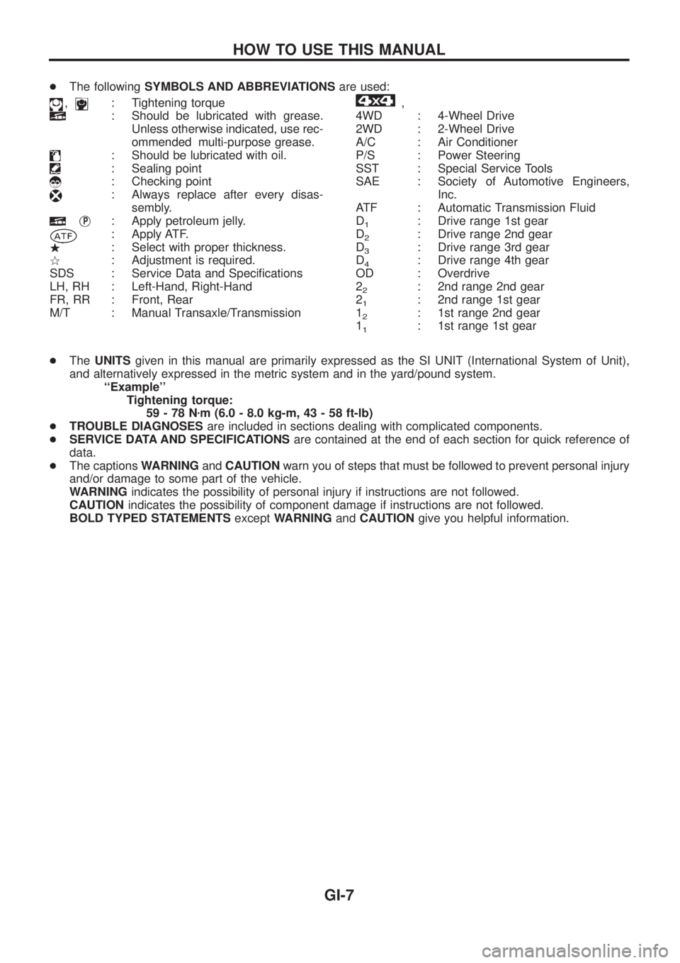
+The followingSYMBOLS AND ABBREVIATIONSare used:
,: Tightening torque
: Should be lubricated with grease.
Unless otherwise indicated, use rec-
ommended multi-purpose grease.
: Should be lubricated with oil.
: Sealing point
: Checking point
: Always replace after every disas-
sembly.
jP: Apply petroleum jelly.
: Apply ATF.
.: Select with proper thickness.
>: Adjustment is required.
SDS : Service Data and Speci®cations
LH, RH : Left-Hand, Right-Hand
FR, RR : Front, Rear
M/T : Manual Transaxle/Transmission
,
4WD : 4-Wheel Drive
2WD : 2-Wheel Drive
A/C : Air Conditioner
P/S : Power Steering
SST : Special Service Tools
SAE : Society of Automotive Engineers,
Inc.
ATF : Automatic Transmission Fluid
D
1: Drive range 1st gear
D
2: Drive range 2nd gear
D
3: Drive range 3rd gear
D
4: Drive range 4th gear
OD : Overdrive
2
2: 2nd range 2nd gear
2
1: 2nd range 1st gear
1
2: 1st range 2nd gear
1
1: 1st range 1st gear
+TheUNITSgiven in this manual are primarily expressed as the SI UNIT (International System of Unit),
and alternatively expressed in the metric system and in the yard/pound system.
``Example''
Tightening torque:
59-78Nzm (6.0 - 8.0 kg-m, 43 - 58 ft-lb)
+TROUBLE DIAGNOSESare included in sections dealing with complicated components.
+SERVICE DATA AND SPECIFICATIONSare contained at the end of each section for quick reference of
data.
+The captionsWARNINGandCAUTIONwarn you of steps that must be followed to prevent personal injury
and/or damage to some part of the vehicle.
WARNINGindicates the possibility of personal injury if instructions are not followed.
CAUTIONindicates the possibility of component damage if instructions are not followed.
BOLD TYPED STATEMENTSexceptWARNINGandCAUTIONgive you helpful information.
HOW TO USE THIS MANUAL
GI-7
Page 977 of 1226
MAINTENANCE
SECTION
MA
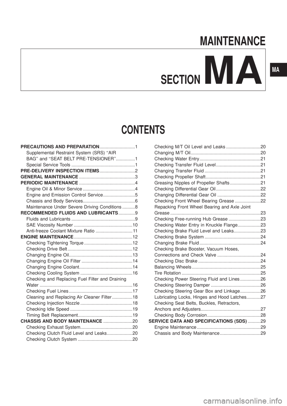
CONTENTS
PRECAUTIONS AND PREPARATION............................1
Supplemental Restraint System (SRS) ``AIR
BAG'' and ``SEAT BELT PRE-TENSIONER''...............1
Special Service Tools ..................................................1
PRE-DELIVERY INSPECTION ITEMS............................2
GENERAL MAINTENANCE............................................3
PERIODIC MAINTENANCE............................................4
Engine Oil & Minor Service .........................................4
Engine and Emission Control Service .........................5
Chassis and Body Services.........................................6
Maintenance Under Severe Driving Conditions ..........8
RECOMMENDED FLUIDS AND LUBRICANTS.............9
Fluids and Lubricants ..................................................9
SAE Viscosity Number ..............................................10
Anti-freeze Coolant Mixture Ratio ............................. 11
ENGINE MAINTENANCE..............................................12
Checking Tightening Torque ......................................12
Checking Drive Belt ...................................................12
Changing Engine Oil..................................................13
Changing Engine Oil Filter ........................................14
Changing Engine Coolant..........................................14
Checking Cooling System .........................................16
Checking and Replacing Fuel Filter and Draining
Water .........................................................................16
Checking Fuel Lines ..................................................17
Cleaning and Replacing Air Cleaner Filter ................18
Checking Injection Nozzle .........................................18
Checking Idle Speed .................................................19
Timing Belt Replacement...........................................19
CHASSIS AND BODY MAINTENANCE.......................20
Checking Exhaust System.........................................20
Checking Clutch Fluid Level and Leaks ....................20
Checking Clutch System ...........................................20Checking M/T Oil Level and Leaks ...........................20
Changing M/T Oil.......................................................20
Checking Water Entry ................................................21
Checking Transfer Fluid Level ...................................21
Changing Transfer Fluid ............................................21
Checking Propeller Shaft ...........................................21
Greasing Nipples of Propeller Shafts ........................21
Checking Differential Gear Oil ...................................22
Changing Differential Gear Oil ..................................22
Checking Front Wheel Bearing Grease ....................22
Repacking Front Wheel Bearing and Axle Joint
Grease .......................................................................23
Checking Free-running Hub Grease .........................23
Checking Water Entry in Knuckle Flange..................23
Checking Brake Fluid Level and Leaks.....................23
Checking Brake System ............................................24
Changing Brake Fluid ................................................24
Checking Brake Booster, Vacuum Hoses,
Connections and Check Valve ..................................24
Checking Disc Brake .................................................24
Balancing Wheels ......................................................25
Tire Rotation ..............................................................25
Checking Power Steering Fluid and Lines ................26
Checking Steering Damper .......................................26
Checking Steering Gear Box and Linkage ................26
Lubricating Locks, Hinges and Hood Latches...........27
Checking Seat Belts, Buckles, Retractors,
Anchors and Adjusters...............................................27
Checking Body Corrosion ..........................................28
SERVICE DATA AND SPECIFICATIONS (SDS)..........29
Engine Maintenance ..................................................29
Chassis and Body Maintenance ................................29
MA
Page 986 of 1226
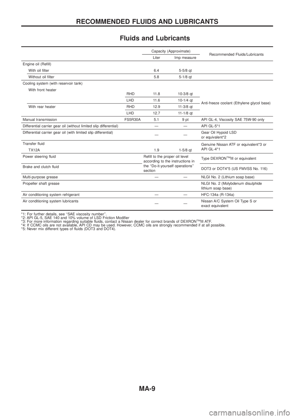
Fluids and Lubricants
Capacity (Approximate)Recommended Fluids/Lubricants
Liter Imp measure
Engine oil (Re®ll) With oil ®lter 6.4 5-5/8 qt
Without oil ®lter 5.8 5-1/8 qt
Cooling system (with reservoir tank)
Anti-freeze coolant (Ethylene glycol base)
With front heater
RHD 11.8 10-3/8 qt
LHD 11.6 10-1/4 qt
With rear heater RHD 12.9 11-3/8 qt LHD 12.7 11-1/8 qt
Manual transmission FS5R30A 5.1 9 pt API GL-4, Viscosity SAE 75W-90 only
Differential carrier gear oil (without limited slip differential) Ð Ð API GL-5*1
Differential carrier gear oil (with limited slip differential) ÐÐGearOilHypoidLSD
orequivalent*2
Transfer ¯uid Genuine Nissan ATF or equivalent*3 or
API GL-4*1
TX12A 1.9 1-5/8 qt
Power steering ¯uid Re®ll to the proper oil level according to the instructions in
the ``Do-it-yourself operations''
sectionType DEXRON
TMIII or equivalent
Brake and clutch ¯uid DOT3 or DOT4*5 (US FMVSS No. 116)
Multi-purpose grease Ð Ð NLGI No. 2 (Lithium soap base)
Propeller shaft grease NLGI No. 2 (Molybdenum disulphide
lithium soap base)
Air conditioning system refrigerant Ð Ð HFC-134a (R-134a)
Air conditioning system lubricants ÐÐNissan A/C System Oil Type S or
exact equivalent
*1: For further details, see ``SAE viscosity number''.
*2:APIGL-5,SAE140and10%volumeofLSDFrictionModi®er
*3: For more information regarding suitable ¯uids, contact a Nissan dealer for correct brands of DEXRON
TMIII ATF.
*4: If CCMC oils are not available, API CD may be used. However, CCMC oils are strongly recommended if at all possible.
*5: Never mix different types of ¯uids (DOT3 and DOT4).
RECOMMENDED FLUIDS AND LUBRICANTS
MA-9
Page 990 of 1226

1. Inspect for cracks, fraying, wear or oil adhesion. Replace if
necessary.
The belts should not touch the bottom of the pulley groove.
2. Check drive belt de¯ection by pushing on the belt midway
between pulleys.
Adjust if belt de¯ections exceed the limit.
Unit: mm (in)
Used belt de¯ection
De¯ection of new belt
LimitDe¯ection after
adjustment
Alternator 17 (0.67) 12 - 14 (0.47 - 0.55) 9 - 11 (0.35 - 0.43)
Air conditioner
compressor11 (0.43)7 - 9 (0.28 - 0.35)6 - 8 (0.24 - 0.31)
Power steering oil
pump14 (0.55) 10 - 12 (0.39 - 0.47) 9 - 11 (0.35 - 0.43)
Applied pushing
force98 N (10 kg, 22 lb)
Check drive belt de¯ections when engine is cold.
Changing Engine Oil
WARNING:
+Be careful not to burn yourself, as engine oil is hot.
+Prolonged and repeated contact with used engine oil may
cause skin cancer; try to avoid direct skin contact with
used oil. If skin contact is made, wash thoroughly with
soap or hand cleaner as soon as possible.
1. Warm up engine, and check for oil leakage from engine com-
ponents.
2. Remove oil ®ller cap and drain plug.
3. Drain oil and ®ll with new engine oil.
Oil grade: CCMC PD1 or PD2
Viscosity:
See ``RECOMMENDED FLUIDS AND
LUBRICANTS'', MA-9.
Re®ll oil capacity (approximate):
Without oil ®lter change
6.4!(5-5/8 Imp qt)
With oil ®lter change
5.8!(5-1/8 Imp qt)
CAUTION:
+Be sure to clean and install oil pan drain plug with washer.
Drain plug:
:29-39Nzm (3.0 - 4.0 kg-m, 22 - 29 ft-lb)
+The re®ll capacity changes depending on the oil tempera-
ture and drain time; use these valves as a reference and be
certain to check with the dipstick when changing the oil.
SMA998C
ENGINE MAINTENANCE
Checking Drive Belt (Cont'd)
MA-13
Page 1003 of 1226
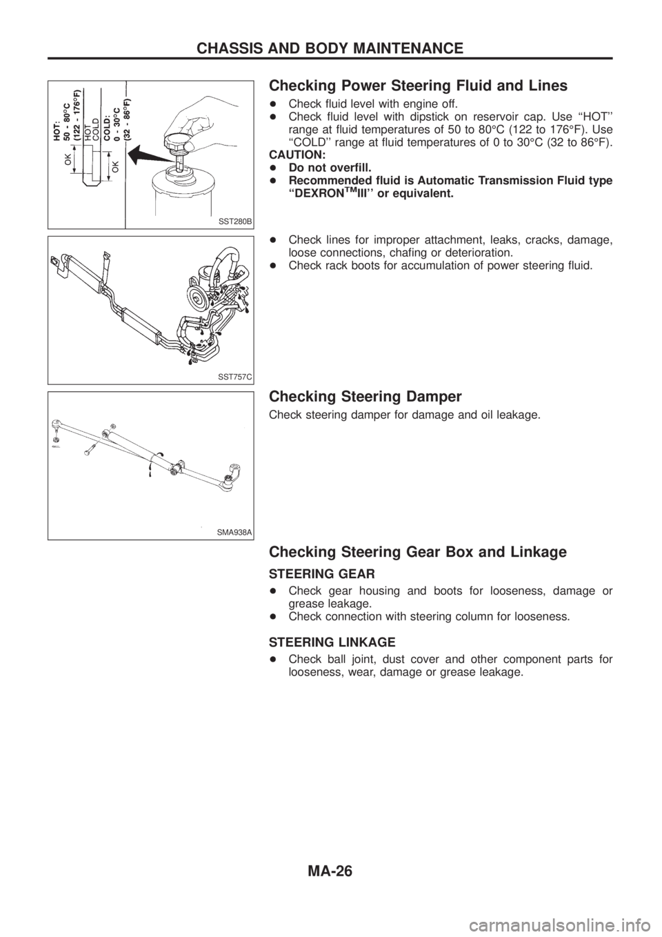
Checking Power Steering Fluid and Lines
+Check ¯uid level with engine off.
+Check ¯uid level with dipstick on reservoir cap. Use ``HOT''
range at ¯uid temperatures of 50 to 80ÉC (122 to 176ÉF). Use
``COLD'' range at ¯uid temperatures of 0 to 30ÉC (32 to 86ÉF).
CAUTION:
+Do not over®ll.
+Recommended ¯uid is Automatic Transmission Fluid type
``DEXRON
TMIII'' or equivalent.
+Check lines for improper attachment, leaks, cracks, damage,
loose connections, cha®ng or deterioration.
+Check rack boots for accumulation of power steering ¯uid.
Checking Steering Damper
Check steering damper for damage and oil leakage.
Checking Steering Gear Box and Linkage
STEERING GEAR
+Check gear housing and boots for looseness, damage or
grease leakage.
+Check connection with steering column for looseness.
STEERING LINKAGE
+Check ball joint, dust cover and other component parts for
looseness, wear, damage or grease leakage.
SST280B
SST757C
SMA938A
CHASSIS AND BODY MAINTENANCE
MA-26
Page 1169 of 1226
STEERING SYSTEM
SECTION
ST
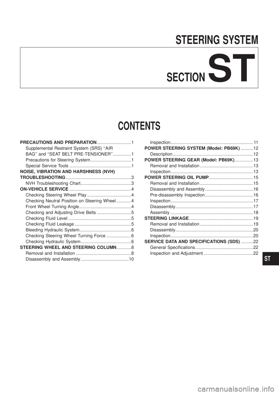
CONTENTS
PRECAUTIONS AND PREPARATION............................1
Supplemental Restraint System (SRS) ``AIR
BAG'' and ``SEAT BELT PRE-TENSIONER''...............1
Precautions for Steering System .................................1
Special Service Tools ..................................................1
NOISE, VIBRATION AND HARSHNESS (NVH)
TROUBLESHOOTING.....................................................3
NVH Troubleshooting Chart.........................................3
ON-VEHICLE SERVICE..................................................4
Checking Steering Wheel Play ....................................4
Checking Neutral Position on Steering Wheel ............4
Front Wheel Turning Angle ..........................................4
Checking and Adjusting Drive Belts ............................5
Checking Fluid Level ...................................................5
Checking Fluid Leakage ..............................................5
Bleeding Hydraulic System..........................................6
Checking Steering Wheel Turning Force ....................6
Checking Hydraulic System.........................................6
STEERING WHEEL AND STEERING COLUMN............8
Removal and Installation .............................................8
Disassembly and Assembly .......................................10Inspection................................................................... 11
POWER STEERING SYSTEM (Model: PB69K)..........12
Description .................................................................12
POWER STEERING GEAR (Model: PB69K)...............13
Removal and Installation ...........................................13
Inspection...................................................................13
POWER STEERING OIL PUMP....................................15
Removal and Installation ...........................................15
Disassembly and Assembly .......................................16
Pre-disassembly Inspection .......................................16
Inspection...................................................................17
Disassembly...............................................................17
Assembly ...................................................................18
STEERING LINKAGE....................................................19
Removal and Installation ...........................................19
Disassembly...............................................................20
Inspection...................................................................20
SERVICE DATA AND SPECIFICATIONS (SDS)..........22
General Speci®cations ...............................................22
Inspection and Adjustment ........................................22
ST
Page 1175 of 1226
Bleeding Hydraulic System
1. Raise front end of vehicle until wheels are clear of the ground.
2. Add ¯uid into oil tank to speci®ed level. Then, quickly turn steer-
ing wheel fully to right and left and lightly touch steering stop-
pers.
Repeat steering wheel operation until ¯uid level no longer
decreases.
3. Start engine.
Repeat step 2 above.
+Incomplete air bleeding will cause the following to occur. When
this happens, bleed air again.
a. Air bubbles in reservoir tank
b. Clicking noise in oil pump
c. Excessive buzzing in oil pump
Fluid noise may occur in the valve or oil pump. This is common
when the vehicle is stationary or while turning steering wheel
slowly. This does not affect performance or durability of the system.
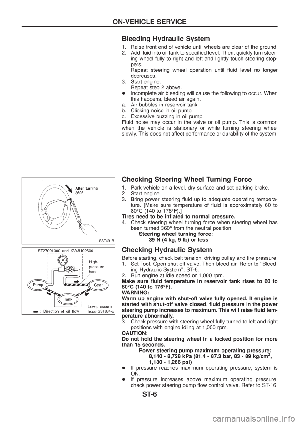
Checking Steering Wheel Turning Force
1. Park vehicle on a level, dry surface and set parking brake.
2. Start engine.
3. Bring power steering ¯uid up to adequate operating tempera-
ture. [Make sure temperature of ¯uid is approximately 60 to
80ÉC (140 to 176ÉF).]
Tires need to be in¯ated to normal pressure.
4. Check steering wheel turning force when steering wheel has
been turned 360É from the neutral position.
Steering wheel turning force:
39 N (4 kg, 9 lb) or less
Checking Hydraulic System
Before starting, check belt tension, driving pulley and tire pressure.
1. Set Tool. Open shut-off valve. Then bleed air. Refer to ``Bleed-
ing Hydraulic System'', ST-6.
2. Run engine at idle speed or 1,000 rpm.
Make sure ¯uid temperature in reservoir tank rises to 60 to
80ÉC (140 to 176ÉF).
WARNING:
Warm up engine with shut-off valve fully opened. If engine is
started with shut-off valve closed, ¯uid pressure in the power
steering pump increases to maximum. This will raise ¯uid tem-
perature abnormally.
3. Check pressure with steering wheel fully turned to left and right
positions with engine idling at 1,000 rpm.
CAUTION:
Do not hold the steering wheel in a locked position for more
than 15 seconds.
Power steering pump maximum operating pressure:
8,140 - 8,728 kPa (81.4 - 87.3 bar, 83 - 89 kg/cm
2,
1,180 - 1,266 psi)
+If pressure reaches maximum operating pressure, system is
OK.
+If pressure increases above maximum operating pressure,
check power steering pump ¯ow control valve. Refer to ST-16.
SST491B
SST834-E
ON-VEHICLE SERVICE
ST-6
Page 1192 of 1226
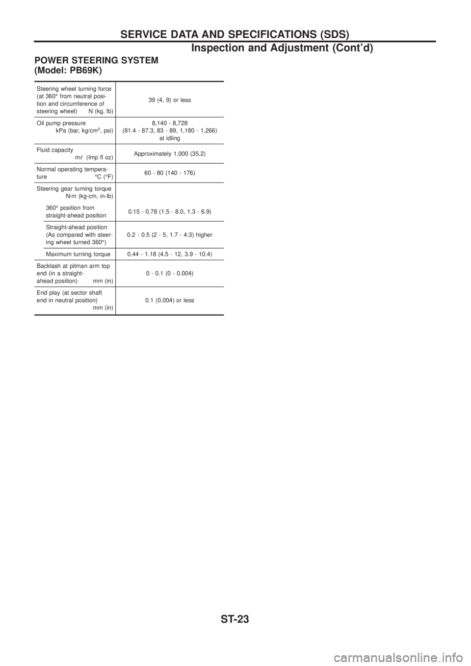
POWER STEERING SYSTEM
(Model: PB69K)
Steering wheel turning force
(at 360É from neutral posi-
tion and circumference of
steering wheel) N (kg, lb)39 (4, 9) or less
Oil pump pressure
kPa (bar, kg/cm
2, psi)8,140 - 8,728
(81.4 - 87.3, 83 - 89, 1,180 - 1,266)
at idling
Fluid capacity
m!(Imp ¯ oz)Approximately 1,000 (35.2)
Normal operating tempera-
ture ÉC (ÉF)60 - 80 (140 - 176)
Steering gear turning torque
Nzm (kg-cm, in-lb)
360É position from
straight-ahead position0.15 - 0.78 (1.5 - 8.0, 1.3 - 6.9)
Straight-ahead position
(As compared with steer-
ing wheel turned 360É)0.2 - 0.5 (2 - 5, 1.7 - 4.3) higher
Maximum turning torque 0.44 - 1.18 (4.5 - 12, 3.9 - 10.4)
Backlash at pitman arm top
end (in a straight-
ahead position) mm (in)0 - 0.1 (0 - 0.004)
End play (at sector shaft
end in neutral position)
mm (in)0.1 (0.004) or less
SERVICE DATA AND SPECIFICATIONS (SDS)
Inspection and Adjustment (Cont'd)
ST-23