2006 NISSAN PATROL air filter
[x] Cancel search: air filterPage 197 of 1226
Basic Inspection
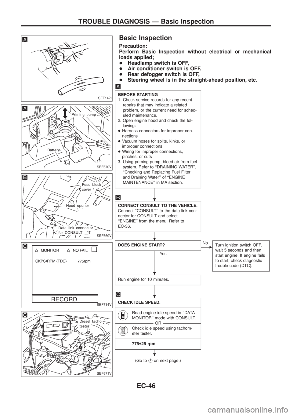
Precaution:
Perform Basic Inspection without electrical or mechanical
loads applied;
+Headlamp switch is OFF,
+Air conditioner switch is OFF,
+Rear defogger switch is OFF,
+Steering wheel is in the straight-ahead position, etc.
BEFORE STARTING
1. Check service records for any recent
repairs that may indicate a related
problem, or the current need for sched-
uled maintenance.
2. Open engine hood and check the fol-
lowing:
+Harness connectors for improper con-
nections
+Vacuum hoses for splits, kinks, or
improper connections
+Wiring for improper connections,
pinches, or cuts
3. Using priming pump, bleed air from fuel
system. Refer to ``DRAINING WATER'',
``Checking and Replacing Fuel Filter
and Draining Water'' of ``ENGINE
MAINTENANCE'' in MA section.
CONNECT CONSULT TO THE VEHICLE.
Connect ``CONSULT'' to the data link con-
nector for CONSULT and select
``ENGINE'' from the menu. Refer to
EC-36.
DOES ENGINE START?
Ye s
cNo
Turn ignition switch OFF,
wait 5 seconds and then
start engine. If engine fails
to start, check diagnostic
trouble code (DTC).
Run engine for 10 minutes.
CHECK IDLE SPEED.
----------------------------------------------------------------------------------------------------------------------------------------------------------------------------------------------------------------------------------------------------------------------------------------------------------------
Read engine idle speed in ``DATA
MONITOR'' mode with CONSULT.
--------------------------------------------------------------------------------------------------------------------------------------OR--------------------------------------------------------------------------------------------------------------------------------------
Check idle speed using tachom-
eter tester.
----------------------------------------------------------------------------------------------------------------------------------------------------------------------------------------------------------------------------------------------------------------------------------------------------------------
775 25 rpm
(Go tojAon next page.)
SEF142I
SEF670V
SEF669V
SEF714V
SEF671V
.
.
.
.
.
TROUBLE DIAGNOSIS Ð Basic Inspection
EC-46
Page 198 of 1226
jA
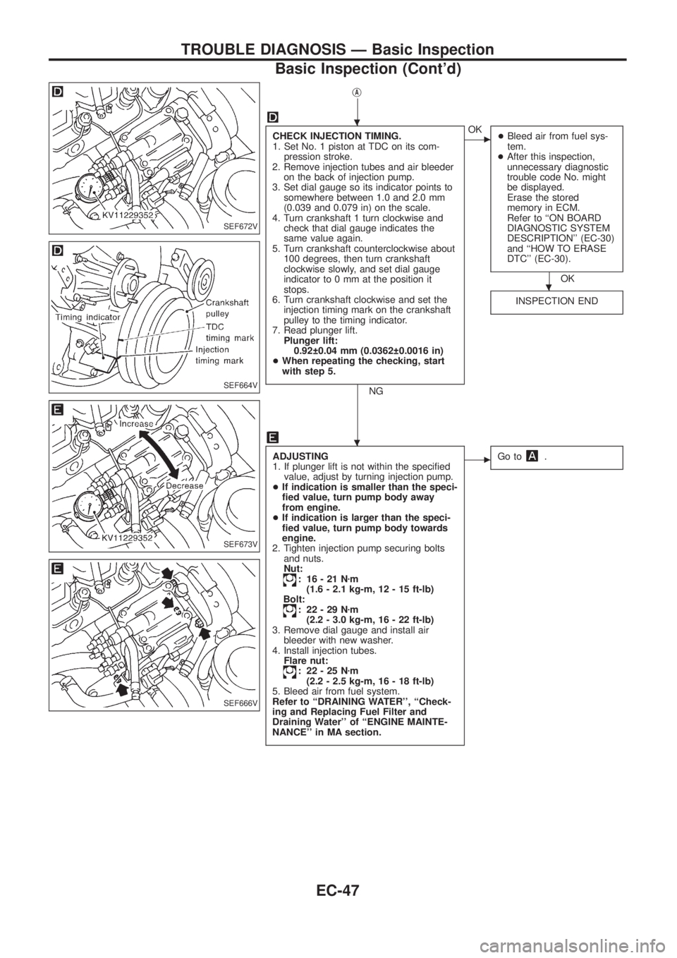
CHECK INJECTION TIMING.
1. Set No. 1 piston at TDC on its com-
pression stroke.
2. Remove injection tubes and air bleeder
on the back of injection pump.
3. Set dial gauge so its indicator points to
somewhere between 1.0 and 2.0 mm
(0.039 and 0.079 in) on the scale.
4. Turn crankshaft 1 turn clockwise and
check that dial gauge indicates the
same value again.
5. Turn crankshaft counterclockwise about
100 degrees, then turn crankshaft
clockwise slowly, and set dial gauge
indicator to 0 mm at the position it
stops.
6. Turn crankshaft clockwise and set the
injection timing mark on the crankshaft
pulley to the timing indicator.
7. Read plunger lift.
Plunger lift:
0.92 0.04 mm (0.0362 0.0016 in)
+When repeating the checking, start
with step 5.
NG
cOK
+Bleed air from fuel sys-
tem.
+After this inspection,
unnecessary diagnostic
trouble code No. might
be displayed.
Erase the stored
memory in ECM.
Refer to ``ON BOARD
DIAGNOSTIC SYSTEM
DESCRIPTION'' (EC-30)
and ``HOW TO ERASE
DTC'' (EC-30).
OK
INSPECTION END
ADJUSTING
1. If plunger lift is not within the speci®ed
value, adjust by turning injection pump.
+If indication is smaller than the speci-
®ed value, turn pump body away
from engine.
+If indication is larger than the speci-
®ed value, turn pump body towards
engine.
2. Tighten injection pump securing bolts
and nuts.
Nut:
: 16-21Nzm
(1.6 - 2.1 kg-m, 12 - 15 ft-lb)
Bolt:
: 22-29Nzm
(2.2 - 3.0 kg-m, 16 - 22 ft-lb)
3. Remove dial gauge and install air
bleeder with new washer.
4. Install injection tubes.
Flare nut:
: 22-25Nzm
(2.2 - 2.5 kg-m, 16 - 18 ft-lb)
5. Bleed air from fuel system.
Refer to ``DRAINING WATER'', ``Check-
ing and Replacing Fuel Filter and
Draining Water'' of ``ENGINE MAINTE-
NANCE'' in MA section.
cGo to.
SEF672V
SEF664V
SEF673V
SEF666V
.
.
.
TROUBLE DIAGNOSIS Ð Basic Inspection
Basic Inspection (Cont'd)
EC-47
Page 255 of 1226
DIAGNOSTIC PROCEDURE
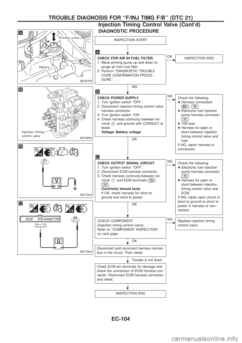
INSPECTION START
CHECK FOR AIR IN FUEL FILTER.
1. Move priming pump up and down to
purge air from fuel ®lter.
2. Perform ``DIAGNOSTIC TROUBLE
CODE CONFIRMATION PROCE-
DURE''.
NG
cOK
INSPECTION END
CHECK POWER SUPPLY.
1. Turn ignition switch ``OFF''.
2. Disconnect injection timing control valve
harness connector.
3. Turn ignition switch ``ON''.
4. Check harness continuity between ter-
minal
V2and ground with CONSULT or
tester.
Voltage: Battery voltage
OK
cNG
Check the following.
+Harness connectors
M51,F6
+Electronic fuel injection
pump harness connector
F3
+10A fuse
+Harness for open or
short between injection
timing control valve and
fuse
If NG, repair harness or
connectors.
CHECK OUTPUT SIGNAL CIRCUIT.
1. Turn ignition switch ``OFF''.
2. Disconnect ECM harness connector.
3. Check harness continuity between ter-
minal
V1and ECM terminals104,
11 0.
Continuity should exist.
If OK, check harness for short to
ground and short to power.
OK
cNG
Check the following.
+Electronic fuel injection
pump harness connector
F3
+Harness for open or
short between injection
timing control valve and
ECM
If NG, repair open circuit or
short to ground or short to
power in harness or con-
nectors.
CHECK COMPONENT
(Injection timing control valve).
Refer to ``COMPONENT INSPECTION''
on next page.
OK
cNG
Replace injection timing
control valve.
Disconnect and reconnect harness connec-
tors in the circuit. Then retest.
Trouble is not ®xed.
Check ECM pin terminals for damage and
check the connection of ECM harness con-
nector. Reconnect ECM harness connector
and retest.
INSPECTION END
SEF670V
SEF685V
SEF754V
SEF755V
.
.
.
.
.
.
.
TROUBLE DIAGNOSIS FOR ``F/INJ TIMG F/B'' (DTC 21)
Injection Timing Control Valve (Cont'd)
EC-104
Page 280 of 1226
DIAGNOSTIC PROCEDURE
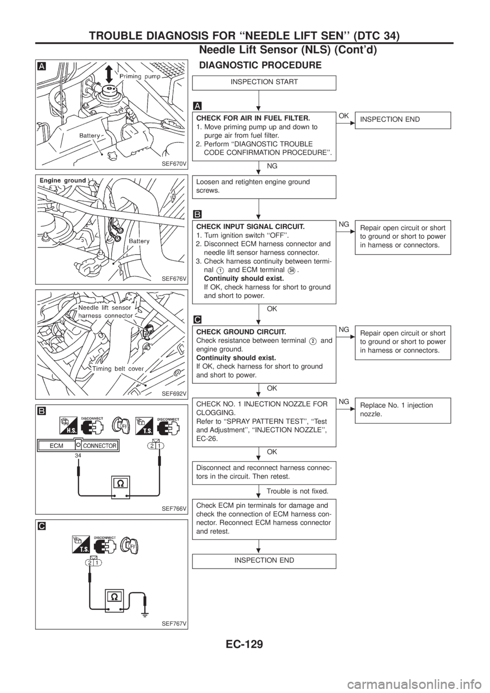
INSPECTION START
CHECK FOR AIR IN FUEL FILTER.
1. Move priming pump up and down to
purge air from fuel ®lter.
2. Perform ``DIAGNOSTIC TROUBLE
CODE CONFIRMATION PROCEDURE''.
NG
cOK
INSPECTION END
Loosen and retighten engine ground
screws.
CHECK INPUT SIGNAL CIRCUIT.
1. Turn ignition switch ``OFF''.
2. Disconnect ECM harness connector and
needle lift sensor harness connector.
3. Check harness continuity between termi-
nal
V1and ECM terminalV34.
Continuity should exist.
If OK, check harness for short to ground
and short to power.
OK
cNG
Repair open circuit or short
to ground or short to power
in harness or connectors.
CHECK GROUND CIRCUIT.
Check resistance between terminal
V2and
engine ground.
Continuity should exist.
If OK, check harness for short to ground
and short to power.
OK
cNG
Repair open circuit or short
to ground or short to power
in harness or connectors.
CHECK NO. 1 INJECTION NOZZLE FOR
CLOGGING.
Refer to ``SPRAY PATTERN TEST'', ``Test
and Adjustment'', ``INJECTION NOZZLE'',
EC-26.
OK
cNG
Replace No. 1 injection
nozzle.
Disconnect and reconnect harness connec-
tors in the circuit. Then retest.
Trouble is not ®xed.
Check ECM pin terminals for damage and
check the connection of ECM harness con-
nector. Reconnect ECM harness connector
and retest.
INSPECTION END
SEF670V
SEF676V
SEF692V
SEF766V
SEF767V
.
.
.
.
.
.
.
.
TROUBLE DIAGNOSIS FOR ``NEEDLE LIFT SEN'' (DTC 34)
Needle Lift Sensor (NLS) (Cont'd)
EC-129
Page 821 of 1226
MANUAL AND AUTO
SERVICE PROCEDURES........................................... 112
HFC-134a (R-134a) Service Procedure .................. 112
Maintenance of Lubricant Quantity in
Compressor ............................................................. 114
Ventilation Air Filter .................................................. 116
Refrigerant Lines ..................................................... 117Checking Refrigerant Leaks .................................... 119
Compressor Mounting .............................................122
Compressor Ð DKS-17CH......................................123
Compressor Clutch ..................................................123
SERVICE DATA AND SPECIFICATIONS...................126
General Speci®cations .............................................126
Inspection and Adjustment ......................................126
When you read wiring diagrams:
+Read GI section, ``HOW TO READ WIRING DIAGRAMS''.
+See EL section, ``POWER SUPPLY ROUTING'' for power distribution circuit.
When you perform trouble diagnoses, read GI section, ``HOW TO FOLLOW FLOW
CHART IN TROUBLE DIAGNOSES'' and ``HOW TO PERFORM EFFICIENT DIAGNOSIS
FOR AN ELECTRICAL INCIDENT''.
Page 937 of 1226

Ventilation Air Filter
FUNCTION
Air inside passenger compartment is kept clean at either recircula-
tion or fresh mode by installing ventilation air ®lter into cooling unit.
REPLACEMENT TIMING
Replace ventilation air ®lter.
Refer to ``PERIODIC MAINTENANCE'' in MA section.
Caution label is ®xed inside the glove box.
REPLACEMENT PROCEDURES
+Remove glove box.
+Remove instrument reinforcement from instrument panel.
+Remove ventilation air ®lter ®xed clip.
+Take out ventilation air ®lter from cooling unit.
+Replace with new one and reinstall on cooling unit.
+Reinstall instrument reinforcement, glove box and undercover.
RHA042G
SHA868E
RHA953F
SERVICE PROCEDURESMANUAL AND AUTO
HA-116
Page 977 of 1226
MAINTENANCE
SECTION
MA
CONTENTS
PRECAUTIONS AND PREPARATION............................1
Supplemental Restraint System (SRS) ``AIR
BAG'' and ``SEAT BELT PRE-TENSIONER''...............1
Special Service Tools ..................................................1
PRE-DELIVERY INSPECTION ITEMS............................2
GENERAL MAINTENANCE............................................3
PERIODIC MAINTENANCE............................................4
Engine Oil & Minor Service .........................................4
Engine and Emission Control Service .........................5
Chassis and Body Services.........................................6
Maintenance Under Severe Driving Conditions ..........8
RECOMMENDED FLUIDS AND LUBRICANTS.............9
Fluids and Lubricants ..................................................9
SAE Viscosity Number ..............................................10
Anti-freeze Coolant Mixture Ratio ............................. 11
ENGINE MAINTENANCE..............................................12
Checking Tightening Torque ......................................12
Checking Drive Belt ...................................................12
Changing Engine Oil..................................................13
Changing Engine Oil Filter ........................................14
Changing Engine Coolant..........................................14
Checking Cooling System .........................................16
Checking and Replacing Fuel Filter and Draining
Water .........................................................................16
Checking Fuel Lines ..................................................17
Cleaning and Replacing Air Cleaner Filter ................18
Checking Injection Nozzle .........................................18
Checking Idle Speed .................................................19
Timing Belt Replacement...........................................19
CHASSIS AND BODY MAINTENANCE.......................20
Checking Exhaust System.........................................20
Checking Clutch Fluid Level and Leaks ....................20
Checking Clutch System ...........................................20Checking M/T Oil Level and Leaks ...........................20
Changing M/T Oil.......................................................20
Checking Water Entry ................................................21
Checking Transfer Fluid Level ...................................21
Changing Transfer Fluid ............................................21
Checking Propeller Shaft ...........................................21
Greasing Nipples of Propeller Shafts ........................21
Checking Differential Gear Oil ...................................22
Changing Differential Gear Oil ..................................22
Checking Front Wheel Bearing Grease ....................22
Repacking Front Wheel Bearing and Axle Joint
Grease .......................................................................23
Checking Free-running Hub Grease .........................23
Checking Water Entry in Knuckle Flange..................23
Checking Brake Fluid Level and Leaks.....................23
Checking Brake System ............................................24
Changing Brake Fluid ................................................24
Checking Brake Booster, Vacuum Hoses,
Connections and Check Valve ..................................24
Checking Disc Brake .................................................24
Balancing Wheels ......................................................25
Tire Rotation ..............................................................25
Checking Power Steering Fluid and Lines ................26
Checking Steering Damper .......................................26
Checking Steering Gear Box and Linkage ................26
Lubricating Locks, Hinges and Hood Latches...........27
Checking Seat Belts, Buckles, Retractors,
Anchors and Adjusters...............................................27
Checking Body Corrosion ..........................................28
SERVICE DATA AND SPECIFICATIONS (SDS)..........29
Engine Maintenance ..................................................29
Chassis and Body Maintenance ................................29
MA
Page 994 of 1226
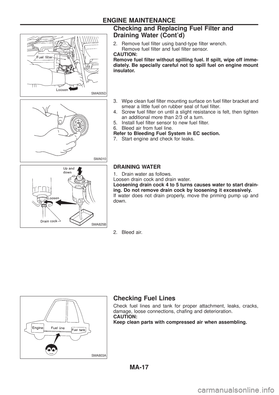
2. Remove fuel ®lter using band-type ®lter wrench.
Remove fuel ®lter and fuel ®lter sensor.
CAUTION:
Remove fuel ®lter without spilling fuel. If spilt, wipe off imme-
diately. Be specially careful not to spill fuel on engine mount
insulator.
3. Wipe clean fuel ®lter mounting surface on fuel ®lter bracket and
smear a little fuel on rubber seal of fuel ®lter.
4. Screw fuel ®lter on until a slight resistance is felt, then tighten
an additional more than 2/3 of a turn.
5. Install fuel ®lter sensor to new fuel ®lter.
6. Bleed air from fuel line.
Refer to Bleeding Fuel System in EC section.
7. Start engine and check for leaks.
DRAINING WATER
1. Drain water as follows.
Loosen drain cock and drain water.
Loosening drain cock 4 to 5 turns causes water to start drain-
ing. Do not remove drain cock by loosening it excessively.
If water does not drain properly, move the priming pump up and
down.
2. Bleed air.
Checking Fuel Lines
Check fuel lines and tank for proper attachment, leaks, cracks,
damage, loose connections, cha®ng and deterioration.
CAUTION:
Keep clean parts with compressed air when assembling.
SMA005D
SMA010
SMA825B
SMA803A
ENGINE MAINTENANCE
Checking and Replacing Fuel Filter and
Draining Water (Cont'd)
MA-17