2006 NISSAN PATROL oil type
[x] Cancel search: oil typePage 401 of 1226
Assembly
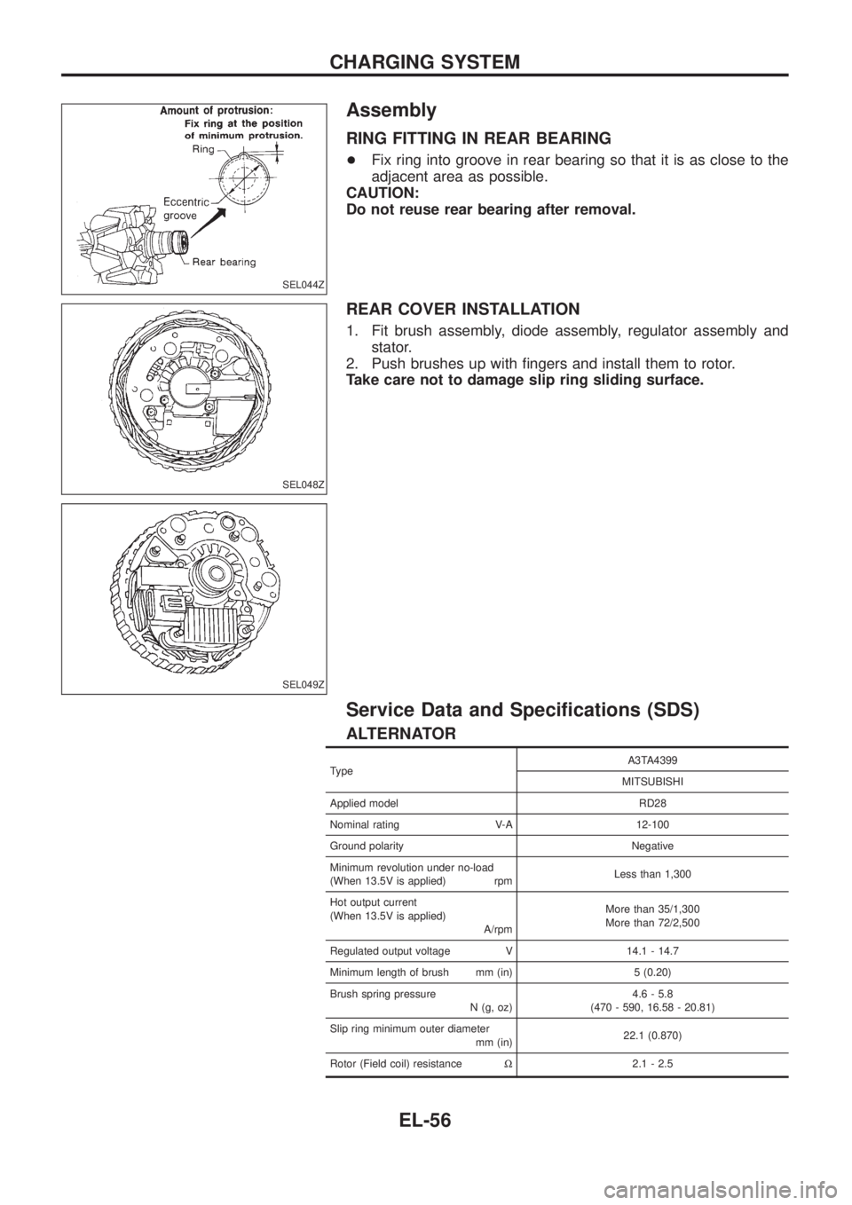
RING FITTING IN REAR BEARING
+Fix ring into groove in rear bearing so that it is as close to the
adjacent area as possible.
CAUTION:
Do not reuse rear bearing after removal.
REAR COVER INSTALLATION
1. Fit brush assembly, diode assembly, regulator assembly and
stator.
2. Push brushes up with ®ngers and install them to rotor.
Take care not to damage slip ring sliding surface.
Service Data and Speci®cations (SDS)
ALTERNATOR
TypeA3TA4399
MITSUBISHI
Applied model RD28
Nominal rating V-A 12-100
Ground polarity Negative
Minimum revolution under no-load
(When 13.5V is applied) rpmLess than 1,300
Hot output current
(When 13.5V is applied)
A/rpmMore than 35/1,300
More than 72/2,500
Regulated output voltage V 14.1 - 14.7
Minimum length of brush mm (in) 5 (0.20)
Brush spring pressure
N (g, oz)4.6 - 5.8
(470 - 590, 16.58 - 20.81)
Slip ring minimum outer diameter
mm (in)22.1 (0.870)
Rotor (Field coil) resistanceW2.1 - 2.5
SEL044Z
SEL048Z
SEL049Z
CHARGING SYSTEM
EL-56
Page 408 of 1226
Bulb Replacement
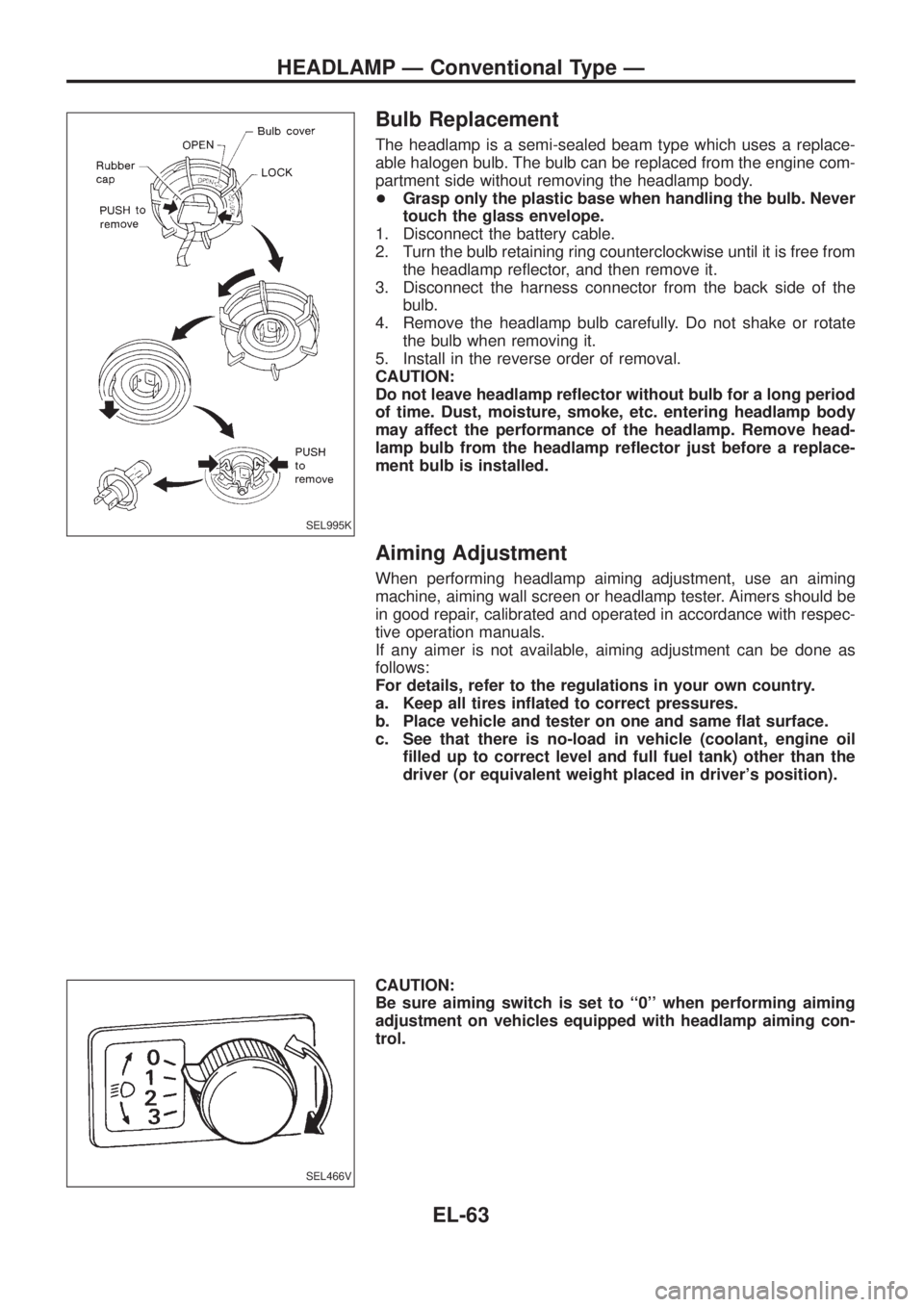
The headlamp is a semi-sealed beam type which uses a replace-
able halogen bulb. The bulb can be replaced from the engine com-
partment side without removing the headlamp body.
+Grasp only the plastic base when handling the bulb. Never
touch the glass envelope.
1. Disconnect the battery cable.
2. Turn the bulb retaining ring counterclockwise until it is free from
the headlamp re¯ector, and then remove it.
3. Disconnect the harness connector from the back side of the
bulb.
4. Remove the headlamp bulb carefully. Do not shake or rotate
the bulb when removing it.
5. Install in the reverse order of removal.
CAUTION:
Do not leave headlamp re¯ector without bulb for a long period
of time. Dust, moisture, smoke, etc. entering headlamp body
may affect the performance of the headlamp. Remove head-
lamp bulb from the headlamp re¯ector just before a replace-
ment bulb is installed.
Aiming Adjustment
When performing headlamp aiming adjustment, use an aiming
machine, aiming wall screen or headlamp tester. Aimers should be
in good repair, calibrated and operated in accordance with respec-
tive operation manuals.
If any aimer is not available, aiming adjustment can be done as
follows:
For details, refer to the regulations in your own country.
a. Keep all tires in¯ated to correct pressures.
b. Place vehicle and tester on one and same ¯at surface.
c. See that there is no-load in vehicle (coolant, engine oil
®lled up to correct level and full fuel tank) other than the
driver (or equivalent weight placed in driver's position).
CAUTION:
Be sure aiming switch is set to ``0'' when performing aiming
adjustment on vehicles equipped with headlamp aiming con-
trol.
SEL995K
SEL466V
HEADLAMP Ð Conventional Type Ð
EL-63
Page 479 of 1226
Electrical Components Inspection
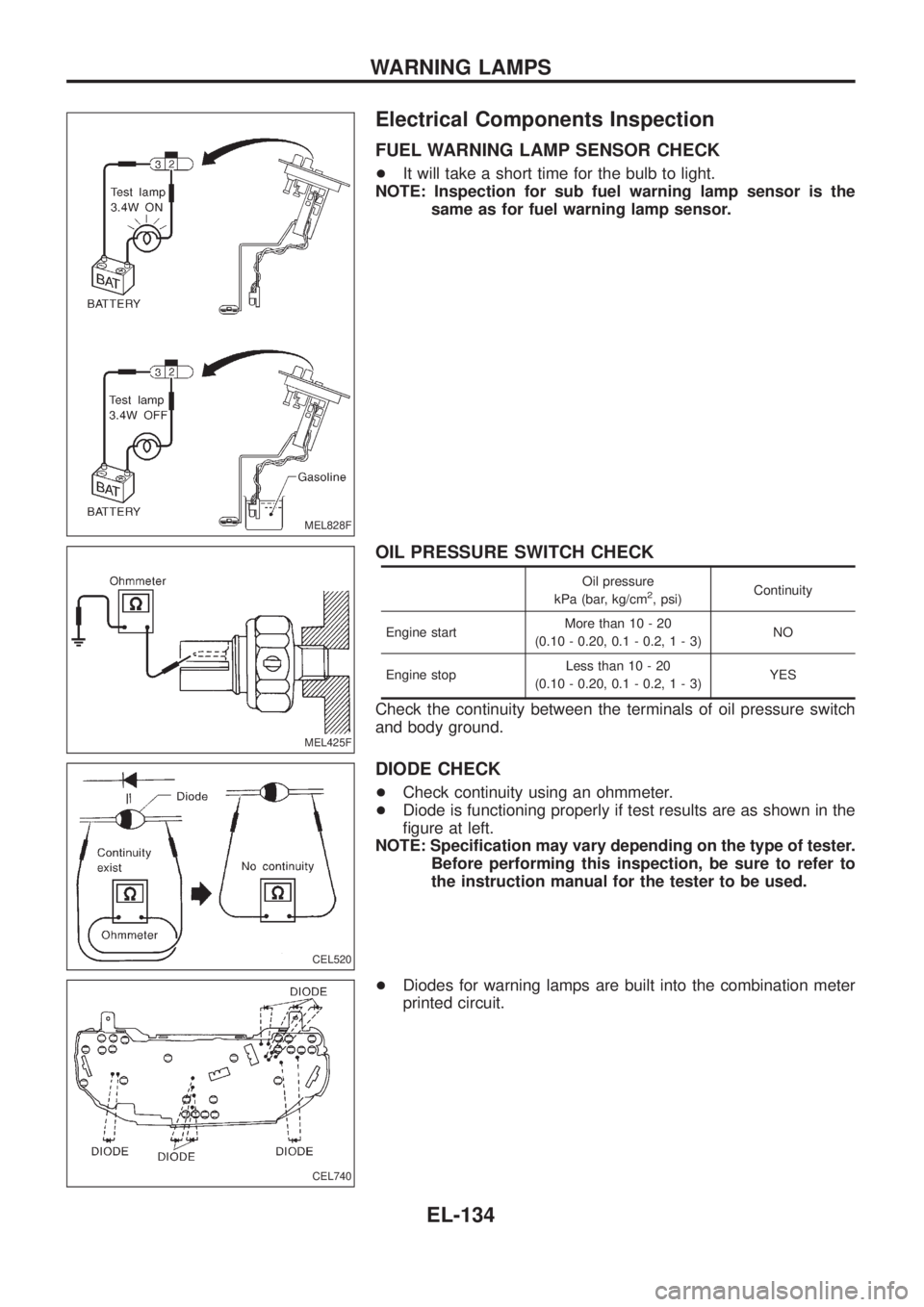
FUEL WARNING LAMP SENSOR CHECK
+It will take a short time for the bulb to light.
NOTE: Inspection for sub fuel warning lamp sensor is the
same as for fuel warning lamp sensor.
OIL PRESSURE SWITCH CHECK
Oil pressure
kPa (bar, kg/cm2, psi)Continuity
Engine startMore than 10 - 20
(0.10 - 0.20, 0.1 - 0.2,1-3)NO
Engine stopLess than 10 - 20
(0.10 - 0.20, 0.1 - 0.2,1-3)YES
Check the continuity between the terminals of oil pressure switch
and body ground.
DIODE CHECK
+Check continuity using an ohmmeter.
+Diode is functioning properly if test results are as shown in the
®gure at left.
NOTE: Speci®cation may vary depending on the type of tester.
Before performing this inspection, be sure to refer to
the instruction manual for the tester to be used.
+Diodes for warning lamps are built into the combination meter
printed circuit.
MEL828F
MEL425F
CEL520
CEL740
WARNING LAMPS
EL-134
Page 676 of 1226
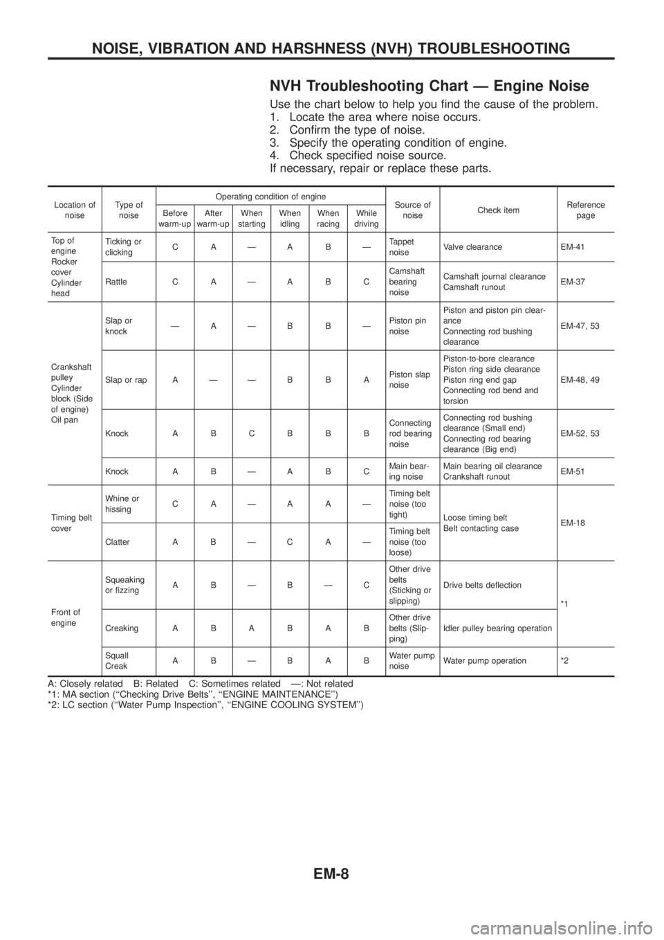
NVH Troubleshooting Chart Ð Engine Noise
Use the chart below to help you ®nd the cause of the problem.
1. Locate the area where noise occurs.
2. Con®rm the type of noise.
3. Specify the operating condition of engine.
4. Check speci®ed noise source.
If necessary, repair or replace these parts.
Location of
noiseType of
noiseOperating condition of engine
Source of
noiseCheck itemReference
page Before
warm-upAfter
warm-upWhen
startingWhen
idlingWhen
racingWhile
driving
To p o f
engine
Rocker
cover
Cylinder
headTicking or
clickingCAÐABÐTappet
noiseValve clearance EM-41
Rattle C A Ð A B CCamshaft
bearing
noiseCamshaft journal clearance
Camshaft runoutEM-37
Crankshaft
pulley
Cylinder
block (Side
of engine)
Oil panSlap or
knockÐAÐB BÐPiston pin
noisePiston and piston pin clear-
ance
Connecting rod bushing
clearanceEM-47, 53
Slap or rap A Ð Ð B B APiston slap
noisePiston-to-bore clearance
Piston ring side clearance
Piston ring end gap
Connecting rod bend and
torsionEM-48, 49
Knock A B C B B BConnecting
rod bearing
noiseConnecting rod bushing
clearance (Small end)
Connecting rod bearing
clearance (Big end)EM-52, 53
Knock A B Ð A B CMain bear-
ing noiseMain bearing oil clearance
Crankshaft runoutEM-51
Timing belt
coverWhine or
hissingCAÐAAÐTiming belt
noise (too
tight)
Loose timing belt
Belt contacting caseEM-18
Clatter A B Ð C A ÐTiming belt
noise (too
loose)
Front of
engineSqueaking
or ®zzingABÐBÐCOther drive
belts
(Sticking or
slipping)Drive belts de¯ection
*1
CreakingABABABOther drive
belts (Slip-
ping)Idler pulley bearing operation
Squall
CreakABÐBABWater pump
noiseWater pump operation *2
A: Closely related B: Related C: Sometimes related Ð: Not related
*1: MA section (``Checking Drive Belts'', ``ENGINE MAINTENANCE'')
*2: LC section (``Water Pump Inspection'', ``ENGINE COOLING SYSTEM'')
NOISE, VIBRATION AND HARSHNESS (NVH) TROUBLESHOOTING
EM-8
Page 760 of 1226
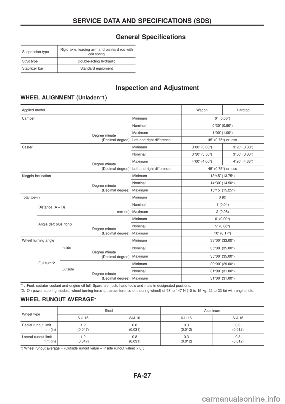
General Speci®cations
Suspension typeRigid axle, leading arm and panhard rod with
coil spring
Strut type Double-acting hydraulic
Stabilizer bar Standard equipment
Inspection and Adjustment
WHEEL ALIGNMENT (Unladen*1)
Applied modelWagon Hardtop
Camber Minimum 0É (0.00É)
Degree minute
(Decimal degree)Nominal 0É30¢(0.50É)
Maximum 1É00¢(1.00É)
Left and right difference 45¢(0.75É) or less
Caster Minimum 3É00¢(3.00É) 3É20¢(3.33É)
Degree minute
(Decimal degree)Nominal 3É30¢(3.50É) 3É50¢(3.83É)
Maximum 4É00¢(4.00É) 4É20¢(4.33É)
Left and right difference 45¢(0.75É) or less
Kingpin inclination Minimum 13É45¢(13.75É)
Degree minute
(Decimal degree)Nominal 14É30¢(14.50É)
Maximum 15É15¢(15.25É)
Total toe-in Minimum 0 (0)
Distance (A þ B)
mm (in)Nominal 1 (0.04)
Maximum 2 (0.08)
Angle (left plus right)
Degree minute
(Decimal degree)Minimum 0¢(0.00É)
Nominal 5¢(0.08É)
Maximum 10¢(0.17É)
Wheel turning angle Minimum 33É00¢(33.00É)
Full turn*2Inside
Degree minute
(Decimal degree)Nominal 35É00¢(35.00É)
Maximum 35É00¢(35.00É)
Outside
Degree minute
(Decimal degree)Minimum 29É00¢(29.00É)
Nominal 31É00¢(31.00É)
Maximum 31É00¢(31.00É)
*1: Fuel, radiator coolant and engine oil full. Spare tire, jack, hand tools and mats in designated positions.
*2: On power steering models, wheel turning force (at circumference of steering wheel) of 98 to 147 N (10 to 15 kg, 22 to 33 lb) with engine idle.
WHEEL RUNOUT AVERAGE*
Wheel typeSteel Aluminum
6JJ-16 8JJ-16 6JJ-16 8JJ-16
Radial runout limit
mm (in)1.2
(0.047)0.8
(0.031)0.3
(0.012)0.3
(0.012)
Lateral runout limit
mm (in)1.2
(0.047)0.8
(0.031)0.3
(0.012)0.3
(0.012)
*: Wheel runout average = (Outside runout value + Inside runout value) x 0.5
SERVICE DATA AND SPECIFICATIONS (SDS)
FA-27
Page 778 of 1226
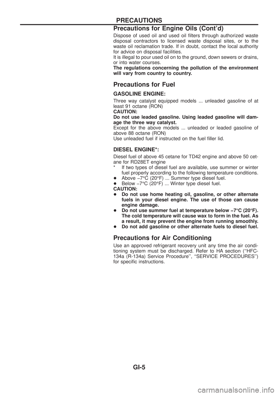
Dispose of used oil and used oil ®lters through authorized waste
disposal contractors to licensed waste disposal sites, or to the
waste oil reclamation trade. If in doubt, contact the local authority
for advice on disposal facilities.
It is illegal to pour used oil on to the ground, down sewers or drains,
or into water courses.
The regulations concerning the pollution of the environment
will vary from country to country.
Precautions for Fuel
GASOLINE ENGINE:
Three way catalyst equipped models ... unleaded gasoline of at
least 91 octane (RON)
CAUTION:
Do not use leaded gasoline. Using leaded gasoline will dam-
age the three way catalyst.
Except for the above models ... unleaded or leaded gasoline of
above 88 octane (RON)
Use unleaded fuel if instructed on the fuel ®ller lid.
DIESEL ENGINE*:
Diesel fuel of above 45 cetane for TD42 engine and above 50 cet-
ane for RD28ET engine
* If two types of diesel fuel are available, use summer or winter
fuel properly according to the following temperature conditions.
+Above þ7ÉC (20ÉF) ... Summer type diesel fuel.
+Below þ7ÉC (20ÉF) ... Winter type diesel fuel.
CAUTION:
+Do not use home heating oil, gasoline, or other alternate
fuels in your diesel engine. The use of those can cause
engine damage.
+Do not use summer fuel at temperature below þ7ÉC (20ÉF).
The cold temperature will cause wax to form in the fuel. As
a result, it may prevent the engine from running smoothly.
+Do not add gasoline or other alternate fuels to diesel fuel.
Precautions for Air Conditioning
Use an approved refrigerant recovery unit any time the air condi-
tioning system must be discharged. Refer to HA section (``HFC-
134a (R-134a) Service Procedure'', ``SERVICE PROCEDURES'')
for speci®c instructions.
PRECAUTIONS
Precautions for Engine Oils (Cont'd)
GI-5
Page 780 of 1226
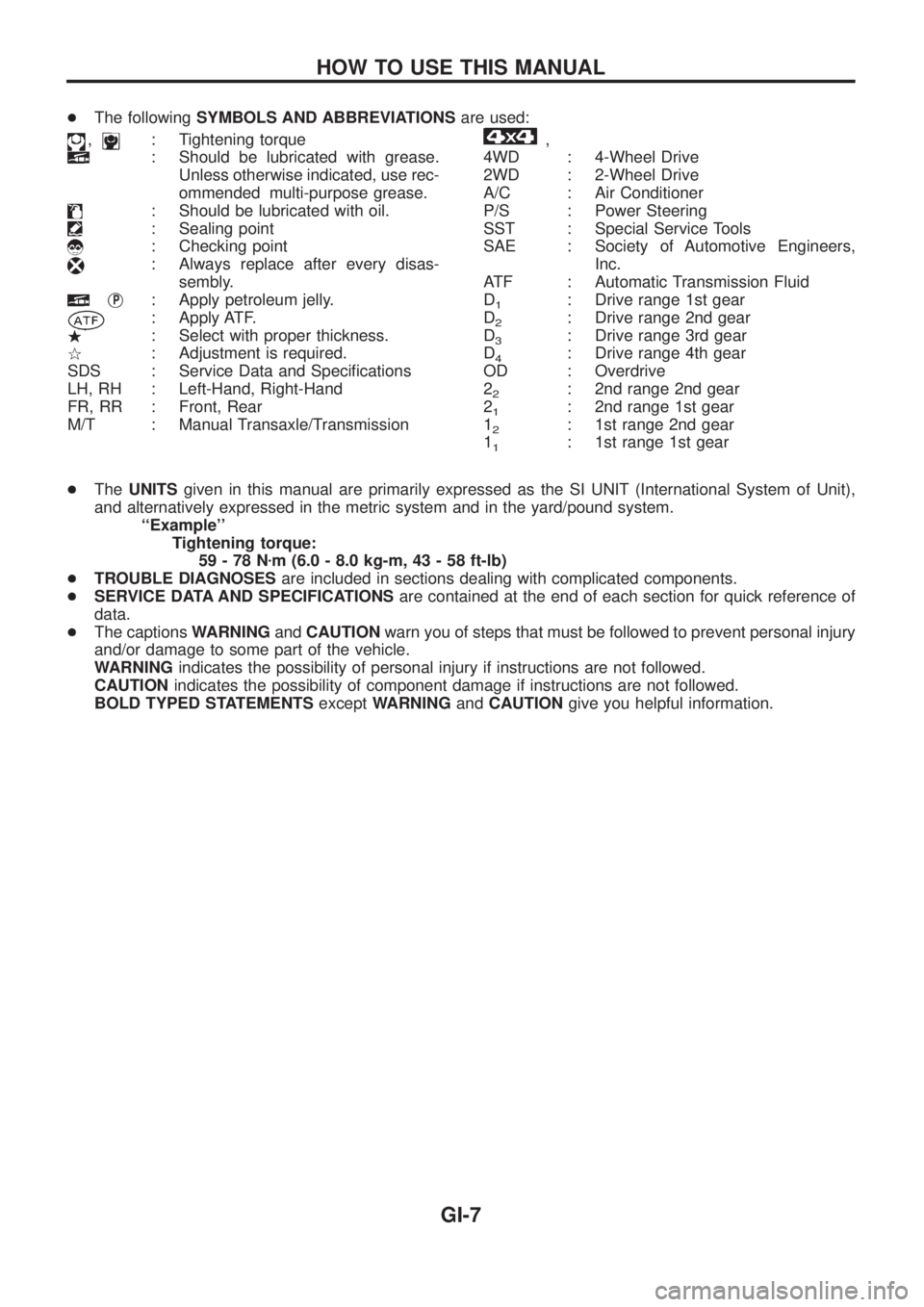
+The followingSYMBOLS AND ABBREVIATIONSare used:
,: Tightening torque
: Should be lubricated with grease.
Unless otherwise indicated, use rec-
ommended multi-purpose grease.
: Should be lubricated with oil.
: Sealing point
: Checking point
: Always replace after every disas-
sembly.
jP: Apply petroleum jelly.
: Apply ATF.
.: Select with proper thickness.
>: Adjustment is required.
SDS : Service Data and Speci®cations
LH, RH : Left-Hand, Right-Hand
FR, RR : Front, Rear
M/T : Manual Transaxle/Transmission
,
4WD : 4-Wheel Drive
2WD : 2-Wheel Drive
A/C : Air Conditioner
P/S : Power Steering
SST : Special Service Tools
SAE : Society of Automotive Engineers,
Inc.
ATF : Automatic Transmission Fluid
D
1: Drive range 1st gear
D
2: Drive range 2nd gear
D
3: Drive range 3rd gear
D
4: Drive range 4th gear
OD : Overdrive
2
2: 2nd range 2nd gear
2
1: 2nd range 1st gear
1
2: 1st range 2nd gear
1
1: 1st range 1st gear
+TheUNITSgiven in this manual are primarily expressed as the SI UNIT (International System of Unit),
and alternatively expressed in the metric system and in the yard/pound system.
``Example''
Tightening torque:
59-78Nzm (6.0 - 8.0 kg-m, 43 - 58 ft-lb)
+TROUBLE DIAGNOSESare included in sections dealing with complicated components.
+SERVICE DATA AND SPECIFICATIONSare contained at the end of each section for quick reference of
data.
+The captionsWARNINGandCAUTIONwarn you of steps that must be followed to prevent personal injury
and/or damage to some part of the vehicle.
WARNINGindicates the possibility of personal injury if instructions are not followed.
CAUTIONindicates the possibility of component damage if instructions are not followed.
BOLD TYPED STATEMENTSexceptWARNINGandCAUTIONgive you helpful information.
HOW TO USE THIS MANUAL
GI-7
Page 822 of 1226
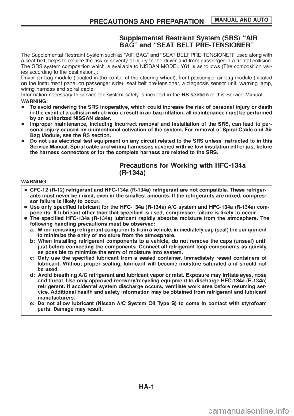
Supplemental Restraint System (SRS) ``AIR
BAG'' and ``SEAT BELT PRE-TENSIONER''
The Supplemental Restraint System such as ``AIR BAG'' and ``SEAT BELT PRE-TENSIONER'' used along with
a seat belt, helps to reduce the risk or severity of injury to the driver and front passenger in a frontal collision.
The SRS system composition which is available to NISSAN MODEL Y61 is as follows (The composition var-
ies according to the destination.):
Driver air bag module (located in the center of the steering wheel), front passenger air bag module (located
on the instrument panel on passenger side), seat belt pre-tensioner, a diagnosis sensor unit, warning lamp,
wiring harness and spiral cable.
Information necessary to service the system safely is included in theRS sectionof this Service Manual.
WARNING:
+To avoid rendering the SRS inoperative, which could increase the risk of personal injury or death
in the event of a collision which would result in air bag in¯ation, all maintenance must be performed
by an authorized NISSAN dealer.
+Improper maintenance, including incorrect removal and installation of the SRS, can lead to per-
sonal injury caused by unintentional activation of the system. For removal of Spiral Cable and Air
Bag Module, see the RS section.
+Do not use electrical test equipment on any circuit related to the SRS unless instructed to in this
Service Manual. Spiral cable and wiring harnesses covered with yellow insulation either just before
the harness connectors or for the complete harness are related to the SRS.
Precautions for Working with HFC-134a
(R-134a)
WARNING:
+CFC-12 (R-12) refrigerant and HFC-134a (R-134a) refrigerant are not compatible. These refriger-
ants must never be mixed, even in the smallest amounts. If the refrigerants are mixed, compres-
sor failure is likely to occur.
+Use only speci®ed lubricant for the HFC-134a (R-134a) A/C system and HFC-134a (R-134a) com-
ponents. If lubricant other than that speci®ed is used, compressor failure is likely to occur.
+The speci®ed HFC-134a (R-134a) lubricant rapidly absorbs moisture from the atmosphere. The
following handling precautions must be observed:
a: When removing refrigerant components from a vehicle, immediately cap (seal) the component
to minimize the entry of moisture from the atmosphere.
b: When installing refrigerant components to a vehicle, do not remove the caps (unseal) until
just before connecting the components. Connect all refrigerant loop components as quickly
as possible to minimize the entry of moisture into system.
c: Only use the speci®ed lubricant from a sealed container. Immediately reseal containers of
lubricant. Without proper sealing, lubricant will become moisture saturated and should not
be used.
d: Avoid breathing A/C refrigerant and lubricant vapor or mist. Exposure may irritate eyes, nose
and throat. Use only approved recovery/recycling equipment to discharge HFC-134a (R-134a)
refrigerant. If accidental system discharge occurs, ventilate work area before resuming ser-
vice. Additional health and safety information may be obtained from refrigerant and lubricant
manufacturers.
e: Do not allow lubricant (Nissan A/C System Oil Type S) to come in contact with styrofoam
parts. Damage may result.
PRECAUTIONS AND PREPARATIONMANUAL AND AUTO
HA-1