2006 NISSAN PATROL service reset
[x] Cancel search: service resetPage 519 of 1226

NATS Audio Link/LHD
DESCRIPTION
The link with the NATS IMMU implies that the radio can basically only be operated if connected to the match-
ing NATS IMMU to which the radio was initially ®tted on the production line.
Since radio operation is impossible after the link with the NATS is disrupted theft of the radio unit is basically
useless since special equipment is required to reset the radio.
Initialisation process for radios that are linked to the NATS IMMU
New radios will be delivered to the factories in the ``NEW'' state, i.e. ready to be linked with the vehicle's NATS.
When the radio in ``NEW'' state is ®rst switched on at the factory, it will start up communication with the vehi-
cle's immobiliser control unit (IMMU) and send a code (the ``Radio Code'') to the IMMU. The IMMU will then
store this code, which is unique to each radio, in its (permanent) memory.
Upon receipt of the code by the IMMU, the NATS will con®rm correct receipt of the radio code to the radio.
Hereafter, the radio will operate as normal.
During the initialisation process, ``NEW'' is displayed on the radio display. Normally though, communication
between Radio and IMMU takes such a short time (300 ms) that the radio seems to switch on directly with-
out showing ``NEW'' on its display.
Normal operation
Each time the radio is switched on afterwards, the radio code will be veri®ed between the radio unit and the
NATS before the radio becomes operational. During the code veri®cation process, ``WAIT'' is shown on the
radio display. Again, the communication takes such a short time (300 ms) that the radio seems to switch on
directly without showing ``WAIT'' on its display.
When the radio is locked
In case of a radio being linked with the vehicle's NATS (immobiliser system), disconnection of the link between
the radio and the IMMU will cause the radio to switch into the lock (``SECURE'') mode in which the radio unit
is fully inoperative. Hence, repair of the radio is basically impossible, unless the radio is reset to the ``NEW''
state for which special decoding equipment is required.
Both Blaupunkt and Clarion have provided their authorized service representatives with so called ``decoder
boxes'' which can bring the radio unit back to the ``NEW'' state, enabling the radio to be switched on after which
repair can be carried out. Subsequently, when the repaired radio is delivered to the ®nal user again, it will be
in the ``NEW'' state as to enable re-linking the radio to the vehicle's immobiliser system. As a result of the
above, repair of the radio can only be done by an authorized Blaupunkt or Clarion representative.
Note:
Radio manufacturer of Nissan Y61 models for Europe is ``Clarion''.
SERVICE PROCEDURE
Item Service procedure Description
Battery disconnection No additional action required. Ð
Radio needs repair Repair needs to be done by authorized represen-
tative of radio manufacturer since radio cannot
be operated unless it is reset to NEW state,
using special decoding equipment.Ð
Replacement of radio by new
partNo additional action required. Radio is delivered in NEW state.
Transferring radio to another
vehicle/replacement of radio
by an ``old'' partRadio needs to be reset to NEW state by autho-
rized representative of radio manufacturer.Ð
Replacement of IMMU by
new partNo additional action required. The new IMMU will be recognized by the radio
since a `blank' code is stored in the memory of
the IMMU. In case the radio recognizes this
`blank' code, it will request for input of the correct
CATS code after which the radio will switch back
to the initialisation process.
AUDIO
EL-174
Page 520 of 1226

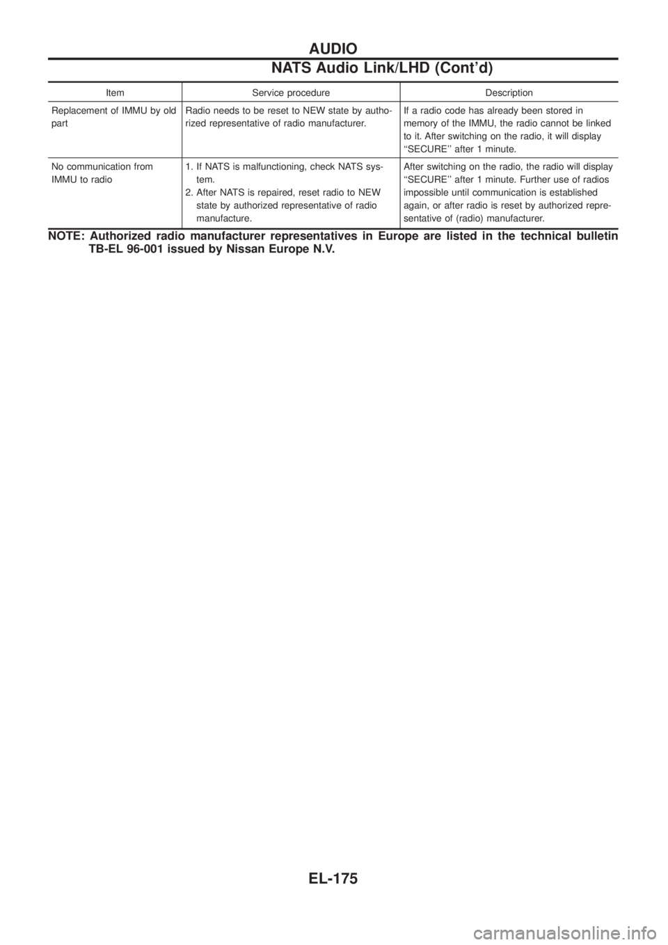
Item Service procedure Description
Replacement of IMMU by old
partRadio needs to be reset to NEW state by autho-
rized representative of radio manufacturer.If a radio code has already been stored in
memory of the IMMU, the radio cannot be linked
to it. After switching on the radio, it will display
``SECURE'' after 1 minute.
No communication from
IMMU to radio1. If NATS is malfunctioning, check NATS sys-
tem.
2. After NATS is repaired, reset radio to NEW
state by authorized representative of radio
manufacture.After switching on the radio, the radio will display
``SECURE'' after 1 minute. Further use of radios
impossible until communication is established
again, or after radio is reset by authorized repre-
sentative of (radio) manufacturer.
NOTE: Authorized radio manufacturer representatives in Europe are listed in the technical bulletin
TB-EL 96-001 issued by Nissan Europe N.V.
AUDIO
NATS Audio Link/LHD (Cont'd)
EL-175
Page 741 of 1226

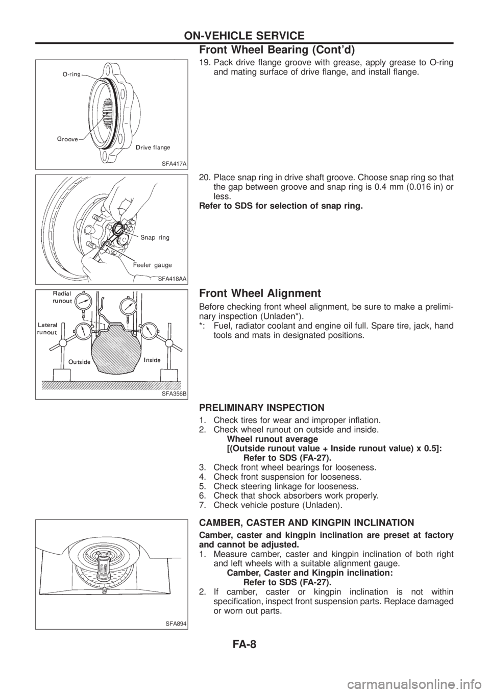
19. Pack drive ¯ange groove with grease, apply grease to O-ring
and mating surface of drive ¯ange, and install ¯ange.
20. Place snap ring in drive shaft groove. Choose snap ring so that
the gap between groove and snap ring is 0.4 mm (0.016 in) or
less.
Refer to SDS for selection of snap ring.
Front Wheel Alignment
Before checking front wheel alignment, be sure to make a prelimi-
nary inspection (Unladen*).
*: Fuel, radiator coolant and engine oil full. Spare tire, jack, hand
tools and mats in designated positions.
PRELIMINARY INSPECTION
1. Check tires for wear and improper in¯ation.
2. Check wheel runout on outside and inside.
Wheel runout average
[(Outside runout value + Inside runout value) x 0.5]:
Refer to SDS (FA-27).
3. Check front wheel bearings for looseness.
4. Check front suspension for looseness.
5. Check steering linkage for looseness.
6. Check that shock absorbers work properly.
7. Check vehicle posture (Unladen).
CAMBER, CASTER AND KINGPIN INCLINATION
Camber, caster and kingpin inclination are preset at factory
and cannot be adjusted.
1. Measure camber, caster and kingpin inclination of both right
and left wheels with a suitable alignment gauge.
Camber, Caster and Kingpin inclination:
Refer to SDS (FA-27).
2. If camber, caster or kingpin inclination is not within
speci®cation, inspect front suspension parts. Replace damaged
or worn out parts.
SFA417A
SFA418AA
SFA356B
SFA894
ON-VEHICLE SERVICE
Front Wheel Bearing (Cont'd)
FA-8
Page 1144 of 1226

Trouble Diagnoses Introduction
CAUTION:
+Do not use a circuit tester to check SRS harness connectors unless instructed to in this Service
Manual. SRS wiring harnesses except for ``SEAT BELT PRE-TENSIONER'' can be identi®ed with
yellow harness protector or yellow insulation tape before the harness connectors.
+Do not attempt to repair, splice or modify the SRS wiring harness. If the harness is damaged,
replace it with a new one.
+Keep ground portion clean.
DIAGNOSIS FUNCTION
The SRS self-diagnosis results can be read by using ``AIR BAG'' warning lamp and/or CONSULT.
System Using CONSULT Using warning lamp
Seat belt pre-tensioner X Ð
Air bag Driver air bag X X
Front passenger air bag X X
The reading of these results is accomplished using one of two modes Ð ``User mode'' and ``Diagnosis mode''.
The User mode is exclusively prepared for the customer (driver). This mode warns the driver of a system
malfunction through the operation of the ``AIR BAG'' warning lamp.
The Diagnosis mode allows the technician to locate and inspect the malfunctioning part.
The mode applications for the ``AIR BAG'' warning lamp and CONSULT are as follows:
User mode Diagnosis mode Display type
``AIR BAG'' warning lamp X X ON-OFF operation
CONSULT Ð X Monitoring
DIAGNOSIS MODE FOR CONSULT
+``SELF-DIAG [CURRENT]''
A current Self-diagnosis result (also indicated by the warning lamp ¯ashes in the Diagnosis mode) is dis-
played on the CONSULT screen in real time. This refers to a malfunctioning part requiring repairs.
+``SELF-DIAG [PAST]''
Diagnosis results previously stored in the memory are displayed on the CONSULT screen. The stored
results are not erased until memory erasing is executed.
+``TROUBLE DIAG RECORD''
With ``TROUBLE DIAG RECORD'', diagnosis results previously erased by a reset operation can be dis-
played on the CONSULT screen.
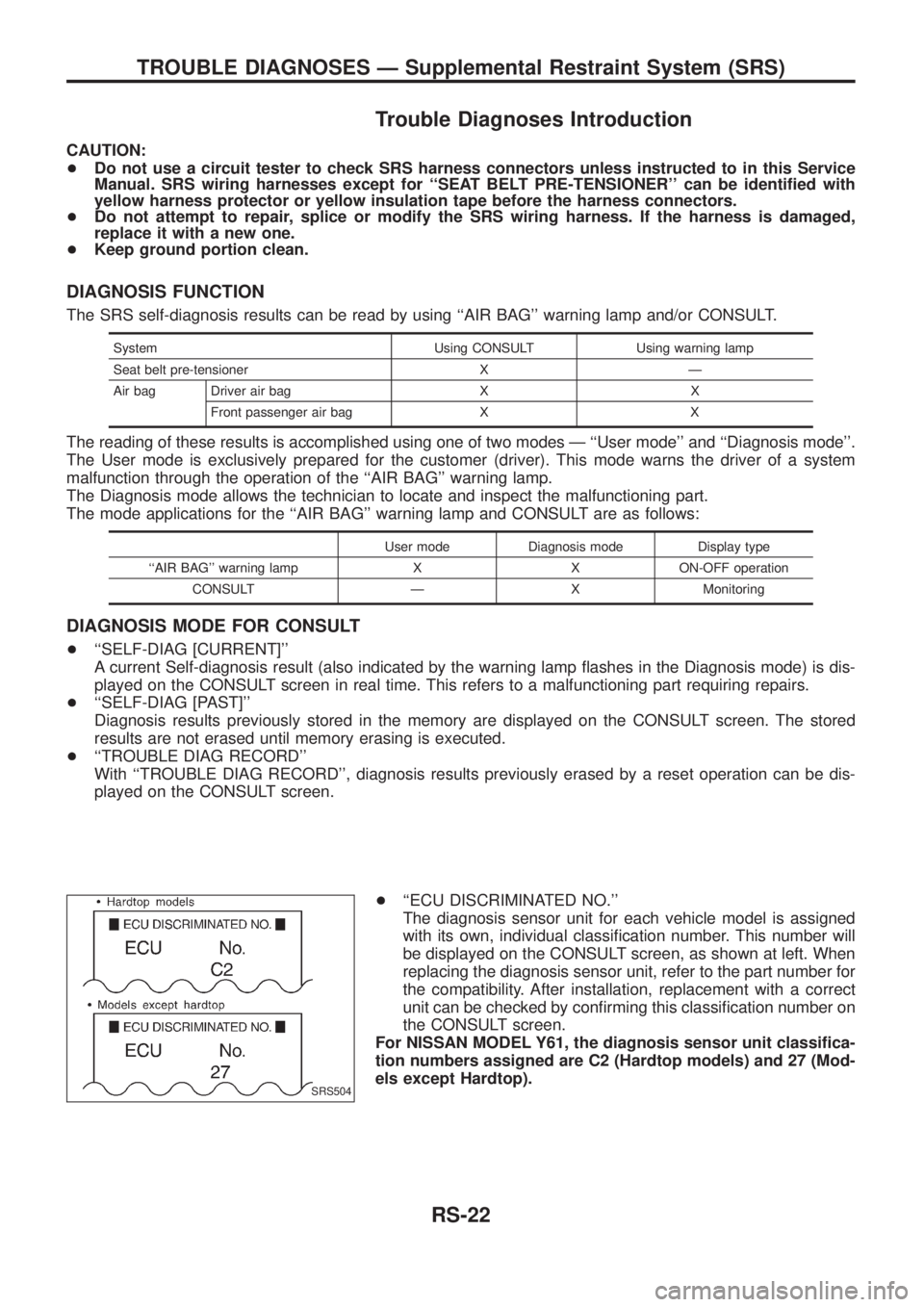
+``ECU DISCRIMINATED NO.''
The diagnosis sensor unit for each vehicle model is assigned
with its own, individual classi®cation number. This number will
be displayed on the CONSULT screen, as shown at left. When
replacing the diagnosis sensor unit, refer to the part number for
the compatibility. After installation, replacement with a correct
unit can be checked by con®rming this classi®cation number on
the CONSULT screen.
For NISSAN MODEL Y61, the diagnosis sensor unit classi®ca-
tion numbers assigned are C2 (Hardtop models) and 27 (Mod-
els except Hardtop).
SRS504
TROUBLE DIAGNOSES Ð Supplemental Restraint System (SRS)
RS-22