2006 NISSAN PATROL brake light
[x] Cancel search: brake lightPage 18 of 1226
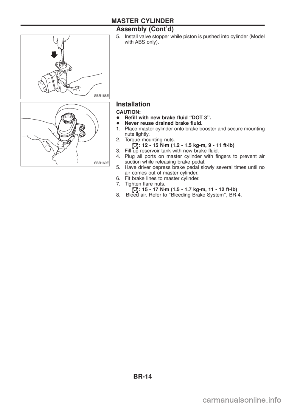
5. Install valve stopper while piston is pushed into cylinder (Modelwith ABS only).
Installation
CAUTION:
+Re®ll with new brake ¯uid ``DOT 3''.
+ Never reuse drained brake ¯uid.
1. Place master cylinder onto brake booster and secure mounting nuts lightly.
2. Torque mounting nuts.
:12-15N zm (1.2 - 1.5 kg-m ,9-11ft-lb)
3. Fill up reservoir tank with new brake ¯uid.
4. Plug all ports on master cylinder with ®ngers to prevent air suction while releasing brake pedal.
5. Have driver depress brake pedal slowly several times until no air comes out of master cylinder.
6. Fit brake lines to master cylinder.
7. Tighten ¯are nuts.
:15-17N zm (1.5 - 1.7 kg-m, 11 - 12 ft-lb)
8. Bleed air. Refer to ``Bleeding Brake System'', BR-4.
SBR168E
SBR169E
MASTER CYLINDER
Assembly (Cont'd)
BR-14
Page 19 of 1226

Brake Booster
ON-VEHICLE SERVICE
Operating check
+Depress brake pedal several times with engine off. After
exhausting vacuum, make sure there is no change in pedal
stroke.
+ Depress brake pedal, then start engine. If pedal goes down
slightly, operation is normal.
Airtight check
+Start engine, and stop it after one or two minutes. Depress
brake pedal several times slowly. Booster is airtight if pedal
stroke is less each time.
+ Depress brake pedal while engine is running, and stop engine
with pedal depressed. The pedal stroke should not change after
holding pedal down for 30 seconds.
REMOVAL
CAUTION:
+Be careful not to splash brake ¯uid on painted areas; it
may cause paint damage. If brake ¯uid is splashed on
painted areas, wash it away with water immediately.
+ Be careful not to deform or bend brake pipes, during
removal of booster.
INSPECTION
Output rod length check
1. Apply vacuum of þ66.7 kPa (þ500 mmHg, þ19.69 inHg) to
brake booster with a hand vacuum pump.
2. Check output rod length. Speci®ed length:10.275 - 10.525 mm (0.4045 - 0.4144 in)
INSTALLATION
CAUTION:
+Be careful not to deform or bend brake pipes during instal-
lation of booster.
+ Replace clevis pin if damaged.
+ Re®ll with new brake ¯uid ``DOT 3''.
+ Never reuse drained brake ¯uid.
+ Take care not to damage brake booster mounting bolt
thread when installing. Due to the narrow angle of
installation, the threads can be damaged by the dash
panel.
SBR002A
SBR365AA
SBR170E
SBR281A
SBR116BF
BRAKE BOOSTER
BR-15
Page 20 of 1226
1. Before ®tting booster, temporarily adjust clevis to dimensionshown.
2. Fit booster, then secure mounting nuts (brake pedal bracket to brake booster) lightly.
3. Connect brake pedal and booster input rod with clevis pin.
4. Secure mounting nuts. Speci®cation: 13 - 16 N zm (1.3 - 1.6 kg-m ,9-12ft-lb)
5. Install master cylinder. Refer to ``Installation'' in ``MASTER CYLINDER'', BR-14.
6. Adjust brake pedal height and free play. Refer to ``Adjustment'' in ``BRAKE PEDAL AND BRACKET'',
BR-10.
7. Secure lock nut for clevis.
:16-22N zm (1.6 - 2.2 kg-m, 12 - 16 ft-lb)
8. Bleed air. Refer to ``Bleeding Brake System'', BR-4.
BRAKE BOOSTER
Brake Booster (Cont'd)
BR-16
Page 37 of 1226

Purpose
The Anti-Lock Brake System (ABS) consists of electronic and hydraulic components. It allows for control of
braking force so locking of the wheels can be avoided.
The ABS:
1) Improves proper tracking performance through steering wheel operation.
2) Eases obstacle avoidance through steering wheel operation.
3) Improves vehicle stability.
Operation
+When the vehicle speed is less than 10 km/h (6 MPH) this system does not work.
+ The Anti-Lock Brake System (ABS) has a self-test function. The system turns on the ABS warning lamp
for 1 second each time the ignition switch is turned ``ON''. After the engine is started, the ABS warning
lamp turns off. The system performs a test the ®rst time the vehicle reaches 6 km/h (4 MPH). A mechani-
cal noise may be heard as the ABS performs this self-test. This is a normal part of the self-test feature. If
a malfunction is found during this check, the ABS warning lamp will stay on.
+ While driving, a mechanical noise may be heard during ABS operation. This is a normal condition.
+ While DIFF-LOCK is on, the anti-lock brake warning light ¯ashes. This indicates that anti-lock may not be
fully operated. (ABS only)
ABS Hydraulic Circuit
j1Inlet solenoid valve
j
2Outlet solenoid valve
j
3Reservoir j
4Pump
j
5Motor
j
6Inlet valve j
7Outlet valve
j
8Bypass check valve
j
9Damper
SBR211E
ANTI-LOCK BRAKE SYSTEM
BR-33
Page 38 of 1226
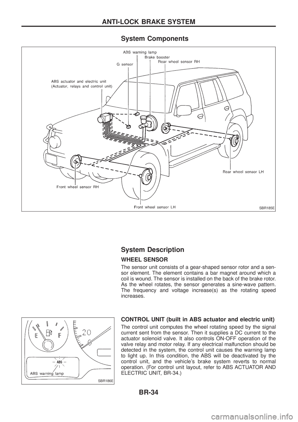
System Components
System Description
WHEEL SENSOR
The sensor unit consists of a gear-shaped sensor rotor and a sen-
sor element. The element contains a bar magnet around which a
coil is wound. The sensor is installed on the back of the brake rotor.
As the wheel rotates, the sensor generates a sine-wave pattern.
The frequency and voltage increase(s) as the rotating speed
increases.
CONTROL UNIT (built in ABS actuator and electric unit)
The control unit computes the wheel rotating speed by the signal
current sent from the sensor. Then it supplies a DC current to the
actuator solenoid valve. It also controls ON-OFF operation of the
valve relay and motor relay. If any electrical malfunction should be
detected in the system, the control unit causes the warning lamp
to light up. In this condition, the ABS will be deactivated by the
control unit, and the vehicle's brake system reverts to normal
operation. (For control unit layout, refer to ABS ACTUATOR AND
ELECTRIC UNIT, BR-34.)
SBR185E
SBR186E
ANTI-LOCK BRAKE SYSTEM
BR-34
Page 51 of 1226
Self-diagnosis
FUNCTION
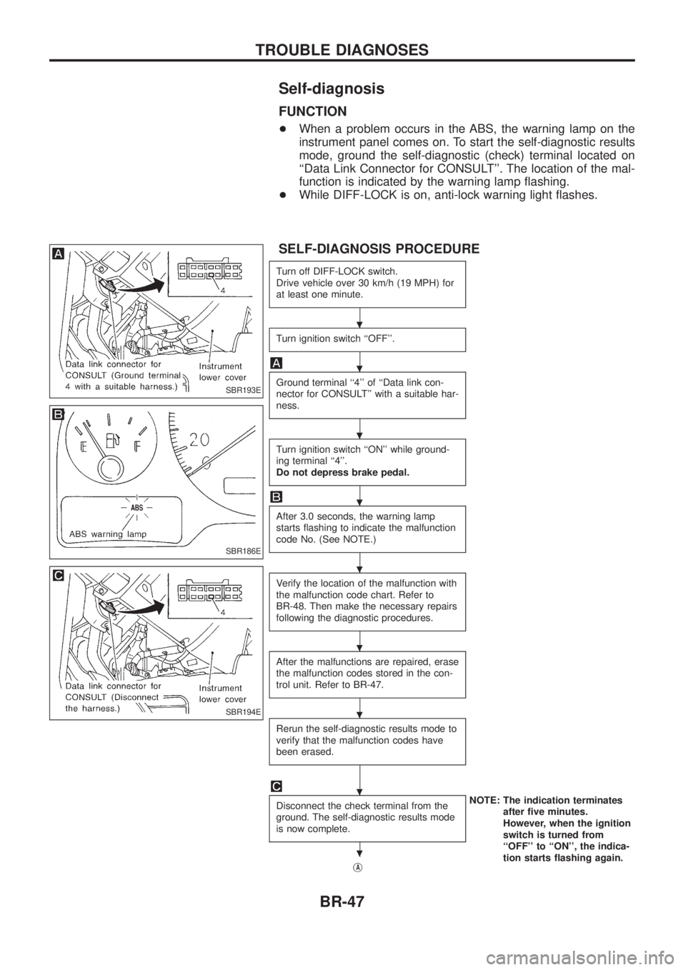
+When a problem occurs in the ABS, the warning lamp on the
instrument panel comes on. To start the self-diagnostic results
mode, ground the self-diagnostic (check) terminal located on
``Data Link Connector for CONSULT''. The location of the mal-
function is indicated by the warning lamp ¯ashing.
+ While DIFF-LOCK is on, anti-lock warning light ¯ashes.
SELF-DIAGNOSIS PROCEDURE
Turn off DIFF-LOCK switch.
Drive vehicle over 30 km/h (19 MPH) for
at least one minute.
Turn ignition switch ``OFF''.
Ground terminal ``4'' of ``Data link con-
nector for CONSULT'' with a suitable har-
ness.
Turn ignition switch ``ON'' while ground-
ing terminal ``4''.
Do not depress brake pedal.
After 3.0 seconds, the warning lamp
starts ¯ashing to indicate the malfunction
code No. (See NOTE.)
Verify the location of the malfunction with
the malfunction code chart. Refer to
BR-48. Then make the necessary repairs
following the diagnostic procedures.
After the malfunctions are repaired, erase
the malfunction codes stored in the con-
trol unit. Refer to BR-47.
Rerun the self-diagnostic results mode to
verify that the malfunction codes have
been erased.
Disconnect the check terminal from the
ground. The self-diagnostic results mode
is now complete.NOTE: The indication terminates
after ®ve minutes.
However, when the ignition
switch is turned from
``OFF'' to ``ON'', the indica-
tion starts ¯ashing again.
j
A
SBR193E
SBR186E
SBR194E
.
.
.
.
.
.
.
.
.
TROUBLE DIAGNOSES
BR-47
Page 660 of 1226

Use the chart below to ®nd out what each wiring diagram code
stands for.
Code Section Wiring Diagram Name
A/C,A HA Auto Air Conditioner
A/C CUT EC Air Conditioner Cut Control
A/C,M HA Manual Air Conditioner
A/T AT A/T
AAC/V EC IACV-AAC Valve
ABS BR Anti-lock Brake System
ACC/SW EC Accelerator Switch (FC)
ACL/SW EC Accelerator Position Switch
ADJRES EC Adjustment Resistor
APS EC Accelerator Position Sensor
ASCD EL Automatic Speed Control Device
AT/C EC A/T Control
AUDIO EL Audio
BACK/L EL Back-up Lamp
BCDD EC BCDD System
CD/CHG EL CD Auto Changer
CHARGE EL Charging System
CHIME EL Warning Chime
CHOKE EC Automatic Choke
CIGAR EL Cigarette Lighter
CKPS EC Crankshaft Position Sensor (OBD)
CLOCK EL Clock
CMPS EC Camshaft Position Sensor
COMPAS EL Compass and Thermometer
COOL/B HA Cool Box
COOL/F EC Cooling Fan Control
CORNER EL Cornering Lamp
CSPS EC Control Sleeve Position Sensor
D/LOCK EL Power Door Lock
DEICER EL Wiper Deicer
DEF EL Rear Window Defogger
DIFF/L PD Differential Lock Control System
DTRL ELHeadlamp Ð With Daytime Light
System
ECTS EC Engine Coolant Temperature Sensor
EGRC/V EC EGRC-Solenoid Valve
F/FOG EL Front Fog Lamp
F/PUMP EC Fuel Pump
FCUT EC Fuel Cut Solenoid Valve
FICD EC IACV-FICD Solenoid Valve
FTS EC Fuel Temperature SensorCode Section Wiring Diagram Name
GLOW EC Quick Glow System
GOVNR EC Electric Governor
H/AIM EL Headlamp Aiming Control System
H/LAMP EL Headlamp
HEATUP EC Heat up Switch
HLC EL Headlamp Cleaner
HORN EL Horn
HSEAT EL Heated Seat
IATS EC Intake Air Temperature Sensor
IC/FAN EC Charge Air Cooler Fan
IGN EC Ignition System
IGN/SG EC Ignition Signal
ILL EL Illumination
INJECT EC Injector
INT/L EL Spot, Vanity Mirror Lamps
KS EC Knock Sensor
MAFS EC Mass Air Flow Sensor
MAIN ECMain Power Supply and Ground Cir-
cuit
METER ELSpeedometer, Tachometer, Temp.,
Oil and Fuel Gauges
MIL/DL EC Mil and Data Link Connectors
MIRROR EL Door Mirror
MULTI EL Multi-remote Control System
NATS EL Nissan Anti-Theft System
NLS EC Needle Lift Sensor
P/ANT EL Power Antenna
PLA EC Partial Load Advance Control
PNP/SW EC Park/Neutral Position Switch
POWER EL Power Supply Routing
PST/SW EC Power Steering Oil Pressure Switch
R/COOL HA Rear Cooler System
R/FOG EL Rear Fog Lamp
R/HEAT HA Rear Heater System
ROOM/L EL Interior Room Lamp
S/LOCK EL Power Door Lock Ð Super Lock
S/SIG EC Start Signal
S/TANK FE Sub Fuel Tank Control System
SEAT EL Power Seat
SROOF EL Sunroof
SRS RS Supplemental Restraint System
WIRING DIAGRAM CODES (CELL CODES)
EL-315
Page 949 of 1226
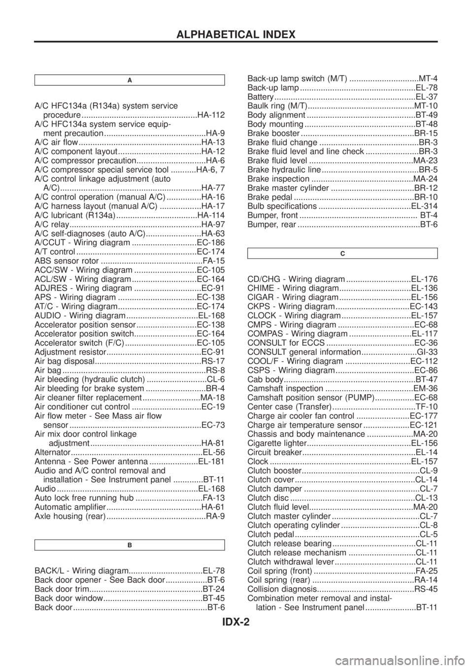
A
A/C HFC134a (R134a) system service
procedure ..................................................HA-112
A/C HFC134a system service equip-
ment precaution ............................................HA-9
A/C air ¯ow .....................................................HA-13
A/C component layout ....................................HA-12
A/C compressor precaution..............................HA-6
A/C compressor special service tool ...........HA-6, 7
A/C control linkage adjustment (auto
A/C).............................................................HA-77
A/C control operation (manual A/C) ...............HA-16
A/C harness layout (manual A/C) ..................HA-17
A/C lubricant (R134a) ...................................HA-114
A/C relay.........................................................HA-97
A/C self-diagnoses (auto A/C)........................HA-63
A/CCUT - Wiring diagram ............................EC-186
A/T control ....................................................EC-174
ABS sensor rotor ............................................FA-15
ACC/SW - Wiring diagram ...........................EC-105
ACL/SW - Wiring diagram ............................EC-164
ADJRES - Wiring diagram .............................EC-91
APS - Wiring diagram ..................................EC-138
AT/C - Wiring diagram..................................EC-174
AUDIO - Wiring diagram ...............................EL-168
Accelerator position sensor ..........................EC-138
Accelerator position switch...........................EC-164
Accelerator switch (F/C) ...............................EC-105
Adjustment resistor.........................................EC-91
Air bag disposal..............................................RS-17
Air bag ..............................................................RS-8
Air bleeding (hydraulic clutch) ..........................CL-6
Air bleeding for brake system ..........................BR-4
Air cleaner ®lter replacement .........................MA-18
Air conditioner cut control ..............................EC-19
Air ¯ow meter - See Mass air ¯ow
sensor .........................................................EC-73
Air mix door control linkage
adjustment ................................................HA-81
Alternator.........................................................EL-56
Antenna - See Power antenna .....................EL-181
Audio and A/C control removal and
installation - See Instrument panel .............BT-11
Audio .............................................................EL-168
Auto lock free running hub .............................FA-13
Automatic ampli®er .........................................HA-61
Axle housing (rear) ...........................................RA-9
B
BACK/L - Wiring diagram................................EL-78
Back door opener - See Back door ..................BT-6
Back door trim.................................................BT-24
Back door window...........................................BT-45
Back door ..........................................................BT-6Back-up lamp switch (M/T) ..............................MT-4
Back-up lamp ..................................................EL-78
Battery .............................................................EL-37
Baulk ring (M/T)..............................................MT-10
Body alignment ...............................................BT-49
Body mounting ................................................BT-48
Brake booster .................................................BR-15
Brake ¯uid change ...........................................BR-3
Brake ¯uid level and line check .......................BR-3
Brake ¯uid level .............................................MA-23
Brake hydraulic line ..........................................BR-5
Brake inspection ............................................MA-24
Brake master cylinder ....................................BR-12
Brake pedal ....................................................BR-10
Bulb speci®cations ........................................EL-314
Bumper, front ................................................... BT-4
Bumper, rear .....................................................BT-6
C
CD/CHG - Wiring diagram ............................EL-176
CHIME - Wiring diagram...............................EL-136
CIGAR - Wiring diagram ...............................EL-156
CKPS - Wiring diagram ................................EC-143
CLOCK - Wiring diagram ..............................EL-157
CMPS - Wiring diagram .................................EC-68
COMPAS - Wiring diagram ...........................EL-117
CONSULT for ECCS ......................................EC-36
CONSULT general information ........................GI-33
COOL/F - Wiring diagram ............................EC-112
CSPS - Wiring diagram ..................................EC-86
Cab body.........................................................BT-47
Camshaft inspection ......................................EM-36
Camshaft position sensor (PUMP).................EC-68
Center case (Transfer) ....................................TF-10
Charge air cooler fan control .......................EC-177
Charge air temperature sensor ....................EC-121
Chassis and body maintenance ....................MA-20
Cigarette lighter.............................................EL-156
Circuit breaker.................................................EL-14
Clock .............................................................EL-157
Clutch booster...................................................CL-9
Clutch cover ....................................................CL-14
Clutch damper ..................................................CL-7
Clutch disc ......................................................CL-13
Clutch ¯uid level.............................................MA-20
Clutch master cylinder ......................................CL-7
Clutch operating cylinder ..................................CL-8
Clutch pedal ......................................................CL-5
Clutch release bearing ....................................CL-11
Clutch release mechanism .............................CL-11
Clutch withdrawal lever ...................................CL-11
Coil spring (front) ............................................FA-25
Coil spring (rear) ............................................RA-14
Collision diagnosis..........................................RS-45
Combination meter removal and instal-
lation - See Instrument panel ......................BT-11
ALPHABETICAL INDEX
IDX-2