2006 NISSAN PATROL tires
[x] Cancel search: tiresPage 6 of 1226
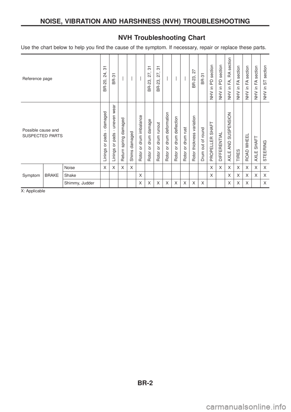
NVH Troubleshooting Chart
Use the chart below to help you ®nd the cause of the symptom. If necessary, repair or replace these parts.
Reference page
BR-20, 24, 31BR-31Ð
Ð
Ð
BR-23, 27, 31
BR-23, 27, 31 Ð
Ð
Ð
BR-23, 27 BR-31
NHV in PD section
NHV in PD section
NHV in FA, RA section
NHV in FA section
NHV in FA section
NHV in FA section
NHV in ST section
Possible cause and
SUSPECTED PARTS
Linings or pads - damaged
Linings or pads - uneven wear
Return spring damaged
Shims damaged
Rotor or drum imbalance
Rotor or drum damage
Rotor or drum runout
Rotor or drum deformation
Rotor or drum de¯ection
Rotor or drum rust
Rotor thickness variation
Drum out of round
PROPELLER SHAFT
DIFFERENTIAL
AXLE AND SUSPENSION
TIRES
ROAD WHEEL
AXLE SHAFT
STEERING
Symptom BRAKE Noise
XXXX XXXXXXX
Shake X X X X X X X
Shimmy, Judder X X XXXXXX XXX X
X: Applicable
NOISE, VIBRATION AND HARSHNESS (NVH) TROUBLESHOOTING
BR-2
Page 408 of 1226
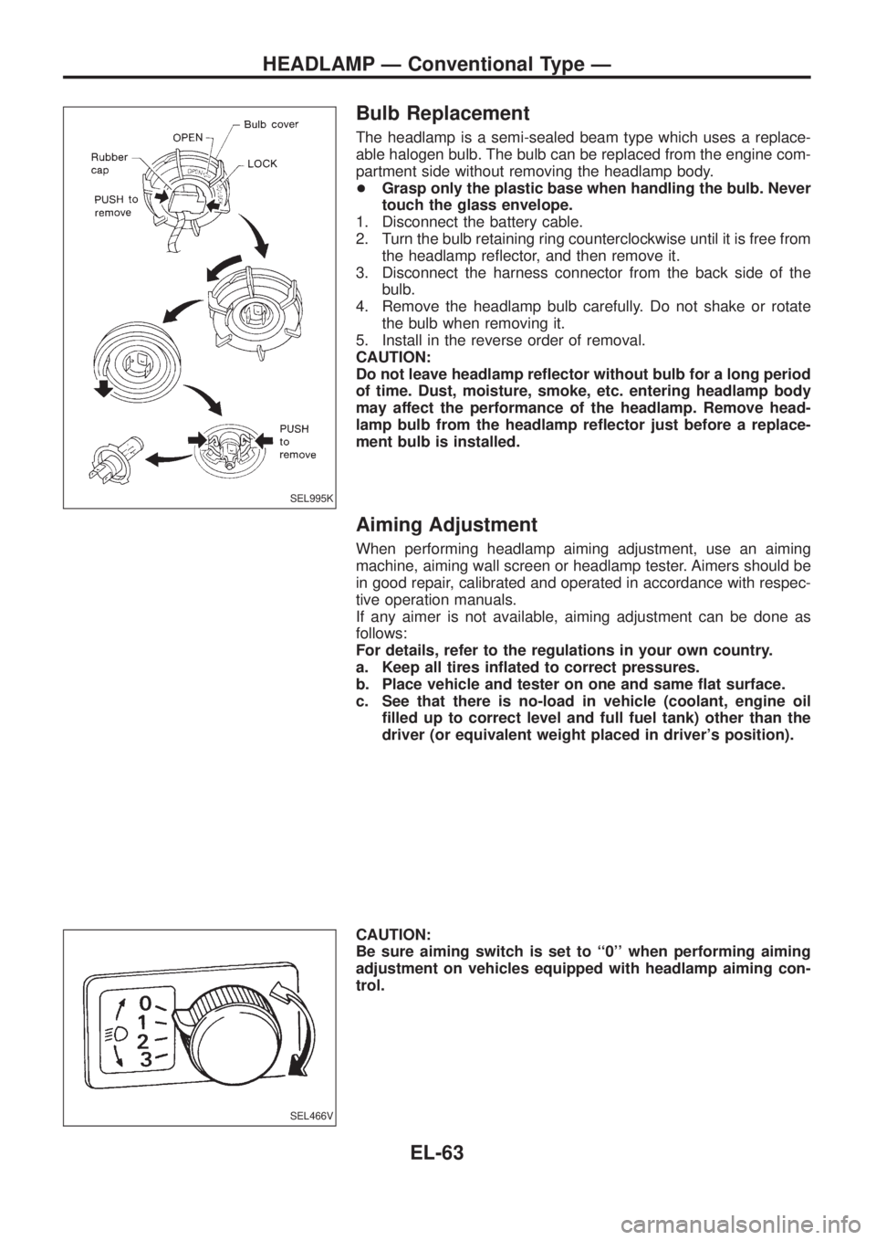
Bulb Replacement
The headlamp is a semi-sealed beam type which uses a replace-
able halogen bulb. The bulb can be replaced from the engine com-
partment side without removing the headlamp body.
+Grasp only the plastic base when handling the bulb. Never
touch the glass envelope.
1. Disconnect the battery cable.
2. Turn the bulb retaining ring counterclockwise until it is free from
the headlamp re¯ector, and then remove it.
3. Disconnect the harness connector from the back side of the
bulb.
4. Remove the headlamp bulb carefully. Do not shake or rotate
the bulb when removing it.
5. Install in the reverse order of removal.
CAUTION:
Do not leave headlamp re¯ector without bulb for a long period
of time. Dust, moisture, smoke, etc. entering headlamp body
may affect the performance of the headlamp. Remove head-
lamp bulb from the headlamp re¯ector just before a replace-
ment bulb is installed.
Aiming Adjustment
When performing headlamp aiming adjustment, use an aiming
machine, aiming wall screen or headlamp tester. Aimers should be
in good repair, calibrated and operated in accordance with respec-
tive operation manuals.
If any aimer is not available, aiming adjustment can be done as
follows:
For details, refer to the regulations in your own country.
a. Keep all tires in¯ated to correct pressures.
b. Place vehicle and tester on one and same ¯at surface.
c. See that there is no-load in vehicle (coolant, engine oil
®lled up to correct level and full fuel tank) other than the
driver (or equivalent weight placed in driver's position).
CAUTION:
Be sure aiming switch is set to ``0'' when performing aiming
adjustment on vehicles equipped with headlamp aiming con-
trol.
SEL995K
SEL466V
HEADLAMP Ð Conventional Type Ð
EL-63
Page 734 of 1226
Precautions
+When installing rubber parts, ®nal tightening must be car-
ried out under unladen condition* with tires on ground.
* Fuel, radiator coolant and engine oil full. Spare tire, jack,
hand tools and mats in designated positions.
+Use ¯are nut wrench when removing and installing brake
tubes.
+After installing removed suspension parts, check wheel
alignment and adjust if necessary.
+Always torque brake lines when installing.
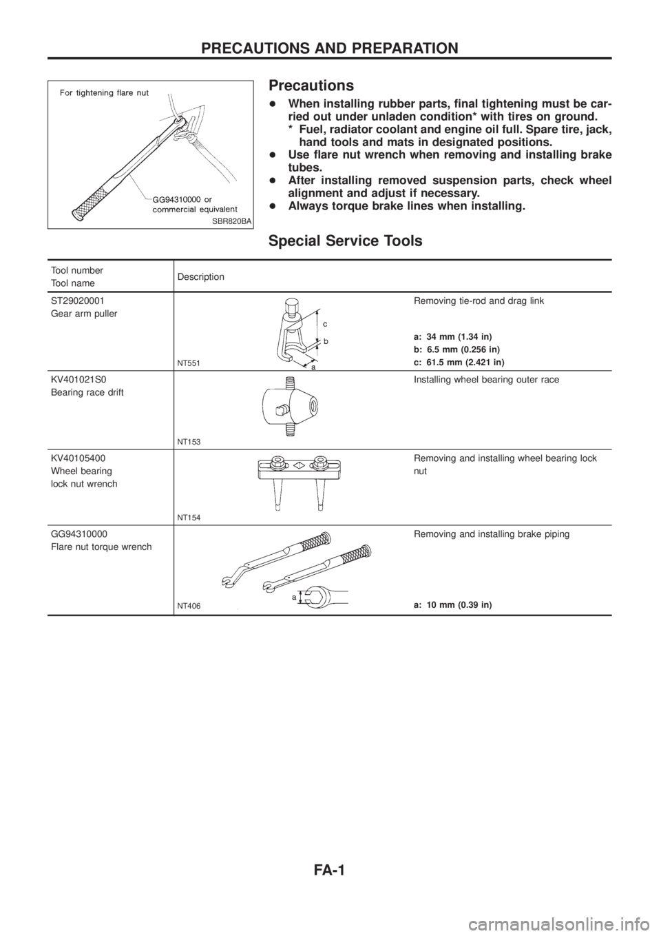
Special Service Tools
Tool number
Tool nameDescription
ST29020001
Gear arm puller
NT551
Removing tie-rod and drag link
a: 34 mm (1.34 in)
b: 6.5 mm (0.256 in)
c: 61.5 mm (2.421 in)
KV401021S0
Bearing race drift
NT153
Installing wheel bearing outer race
KV40105400
Wheel bearing
lock nut wrench
NT154
Removing and installing wheel bearing lock
nut
GG94310000
Flare nut torque wrench
NT406
Removing and installing brake piping
a: 10 mm (0.39 in)
SBR820BA
PRECAUTIONS AND PREPARATION
FA-1
Page 736 of 1226
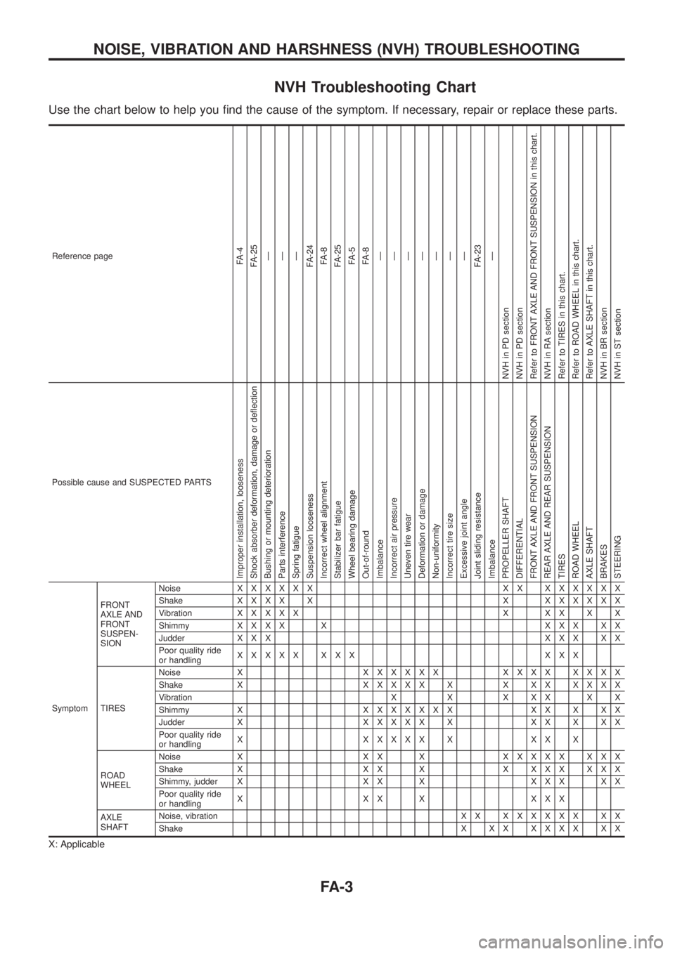
NVH Troubleshooting Chart
Use the chart below to help you ®nd the cause of the symptom. If necessary, repair or replace these parts.
Reference pageFA-4
FA-25
Ð
Ð
Ð
FA-24
FA-8
FA-25
FA-5
FA-8
Ð
Ð
Ð
Ð
Ð
Ð
Ð
FA-23
Ð
NVH in PD section
NVH in PD section
Refer to FRONT AXLE AND FRONT SUSPENSION in this chart.
NVH in RA section
Refer to TIRES in this chart.
Refer to ROAD WHEEL in this chart.
Refer to AXLE SHAFT in this chart.
NVH in BR section
NVH in ST section
Possible cause and SUSPECTED PARTS
Improper installation, looseness
Shock absorber deformation, damage or de¯ection
Bushing or mounting deterioration
Parts interference
Spring fatigue
Suspension looseness
Incorrect wheel alignment
Stabilizer bar fatigue
Wheel bearing damage
Out-of-round
Imbalance
Incorrect air pressure
Uneven tire wear
Deformation or damage
Non-uniformity
Incorrect tire size
Excessive joint angle
Joint sliding resistance
Imbalance
PROPELLER SHAFT
DIFFERENTIAL
FRONT AXLE AND FRONT SUSPENSION
REAR AXLE AND REAR SUSPENSION
TIRES
ROAD WHEEL
AXLE SHAFT
BRAKES
STEERING
SymptomFRONT
AXLE AND
FRONT
SUSPEN-
SIONNoiseXXXXXX XX XXXXXX
ShakeXXXX X X XXXXXX
VibrationXXXXX X XX X X
ShimmyXXXX X XXX XX
Judder X X XXXX XX
Poor quality ride
or handlingXXXXX XXX XXX
TIRESNoise XXXXXXX XXXX XXXX
Shake XXXXXX X X XX XXXX
Vibration X X X X X X X
Shimmy XXXXXXXX XX X XX
Judder XXXXXX X XX X XX
Poor quality ride
or handlingX XXXXX X XX X
ROAD
WHEELNoise X X X XXXXXX XXX
Shake X X X X X X X X X X X
Shimmy, judder X X X X X X X X X
Poor quality ride
or handlingX XX X XXX
AXLE
SHAFTNoise, vibration X XXXXXXX XX
ShakeX XX XXXX XX
X: Applicable
NOISE, VIBRATION AND HARSHNESS (NVH) TROUBLESHOOTING
FA-3
Page 741 of 1226
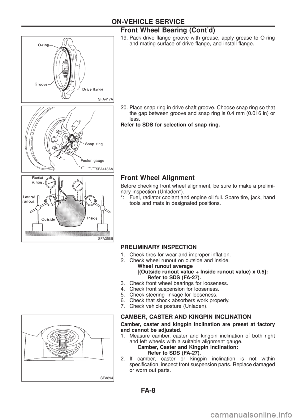
19. Pack drive ¯ange groove with grease, apply grease to O-ring
and mating surface of drive ¯ange, and install ¯ange.
20. Place snap ring in drive shaft groove. Choose snap ring so that
the gap between groove and snap ring is 0.4 mm (0.016 in) or
less.
Refer to SDS for selection of snap ring.
Front Wheel Alignment
Before checking front wheel alignment, be sure to make a prelimi-
nary inspection (Unladen*).
*: Fuel, radiator coolant and engine oil full. Spare tire, jack, hand
tools and mats in designated positions.
PRELIMINARY INSPECTION
1. Check tires for wear and improper in¯ation.
2. Check wheel runout on outside and inside.
Wheel runout average
[(Outside runout value + Inside runout value) x 0.5]:
Refer to SDS (FA-27).
3. Check front wheel bearings for looseness.
4. Check front suspension for looseness.
5. Check steering linkage for looseness.
6. Check that shock absorbers work properly.
7. Check vehicle posture (Unladen).
CAMBER, CASTER AND KINGPIN INCLINATION
Camber, caster and kingpin inclination are preset at factory
and cannot be adjusted.
1. Measure camber, caster and kingpin inclination of both right
and left wheels with a suitable alignment gauge.
Camber, Caster and Kingpin inclination:
Refer to SDS (FA-27).
2. If camber, caster or kingpin inclination is not within
speci®cation, inspect front suspension parts. Replace damaged
or worn out parts.
SFA417A
SFA418AA
SFA356B
SFA894
ON-VEHICLE SERVICE
Front Wheel Bearing (Cont'd)
FA-8
Page 742 of 1226
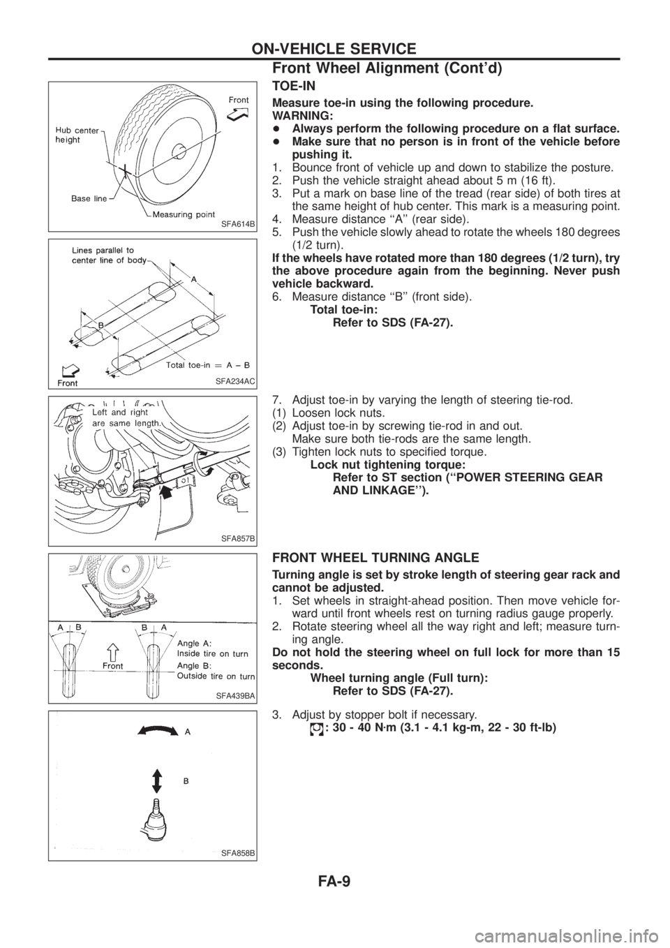
TOE-IN
Measure toe-in using the following procedure.
WARNING:
+Always perform the following procedure on a ¯at surface.
+Make sure that no person is in front of the vehicle before
pushing it.
1. Bounce front of vehicle up and down to stabilize the posture.
2. Push the vehicle straight ahead about 5 m (16 ft).
3. Put a mark on base line of the tread (rear side) of both tires at
the same height of hub center. This mark is a measuring point.
4. Measure distance ``A'' (rear side).
5. Push the vehicle slowly ahead to rotate the wheels 180 degrees
(1/2 turn).
If the wheels have rotated more than 180 degrees (1/2 turn), try
the above procedure again from the beginning. Never push
vehicle backward.
6. Measure distance ``B'' (front side).
Total toe-in:
Refer to SDS (FA-27).
7. Adjust toe-in by varying the length of steering tie-rod.
(1) Loosen lock nuts.
(2) Adjust toe-in by screwing tie-rod in and out.
Make sure both tie-rods are the same length.
(3) Tighten lock nuts to speci®ed torque.
Lock nut tightening torque:
Refer to ST section (``POWER STEERING GEAR
AND LINKAGE'').
FRONT WHEEL TURNING ANGLE
Turning angle is set by stroke length of steering gear rack and
cannot be adjusted.
1. Set wheels in straight-ahead position. Then move vehicle for-
ward until front wheels rest on turning radius gauge properly.
2. Rotate steering wheel all the way right and left; measure turn-
ing angle.
Do not hold the steering wheel on full lock for more than 15
seconds.
Wheel turning angle (Full turn):
Refer to SDS (FA-27).
3. Adjust by stopper bolt if necessary.
:30-40Nzm (3.1 - 4.1 kg-m, 22 - 30 ft-lb)
SFA614B
SFA234AC
SFA857B
SFA439BA
SFA858B
ON-VEHICLE SERVICE
Front Wheel Alignment (Cont'd)
FA-9
Page 773 of 1226
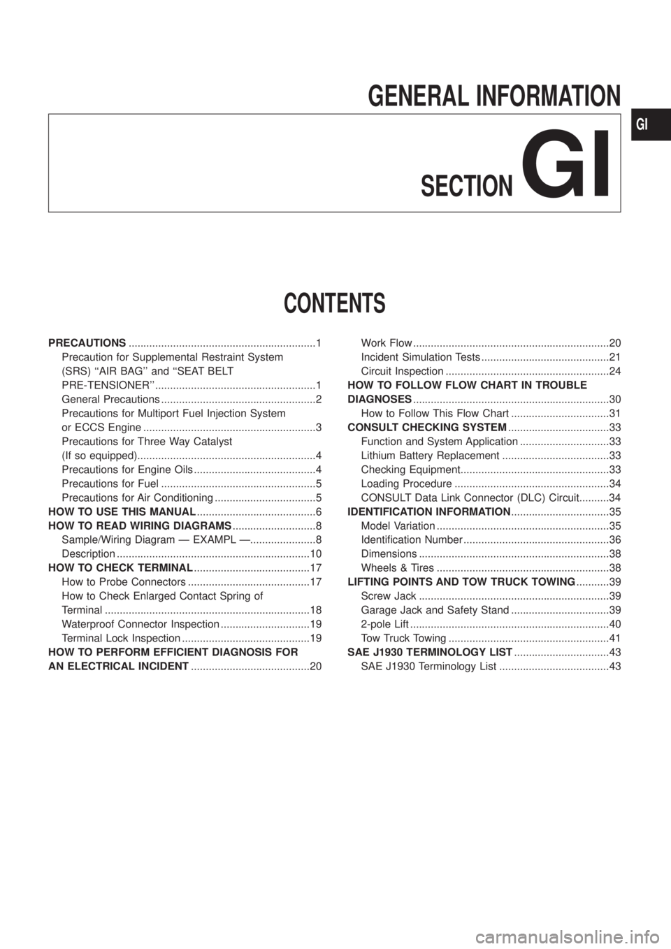
GENERAL INFORMATION
SECTION
GI
CONTENTS
PRECAUTIONS...............................................................1
Precaution for Supplemental Restraint System
(SRS) ``AIR BAG'' and ``SEAT BELT
PRE-TENSIONER'' ......................................................1
General Precautions ....................................................2
Precautions for Multiport Fuel Injection System
or ECCS Engine ..........................................................3
Precautions for Three Way Catalyst
(If so equipped)............................................................4
Precautions for Engine Oils .........................................4
Precautions for Fuel ....................................................5
Precautions for Air Conditioning ..................................5
HOW TO USE THIS MANUAL........................................6
HOW TO READ WIRING DIAGRAMS............................8
Sample/Wiring Diagram Ð EXAMPL Ð......................8
Description .................................................................10
HOW TO CHECK TERMINAL.......................................17
How to Probe Connectors .........................................17
How to Check Enlarged Contact Spring of
Terminal .....................................................................18
Waterproof Connector Inspection ..............................19
Terminal Lock Inspection ...........................................19
HOW TO PERFORM EFFICIENT DIAGNOSIS FOR
AN ELECTRICAL INCIDENT........................................20Work Flow ..................................................................20
Incident Simulation Tests ...........................................21
Circuit Inspection .......................................................24
HOW TO FOLLOW FLOW CHART IN TROUBLE
DIAGNOSES..................................................................30
How to Follow This Flow Chart .................................31
CONSULT CHECKING SYSTEM..................................33
Function and System Application ..............................33
Lithium Battery Replacement ....................................33
Checking Equipment..................................................33
Loading Procedure ....................................................34
CONSULT Data Link Connector (DLC) Circuit..........34
IDENTIFICATION INFORMATION.................................35
Model Variation ..........................................................35
Identi®cation Number .................................................36
Dimensions ................................................................38
Wheels & Tires ..........................................................38
LIFTING POINTS AND TOW TRUCK TOWING...........39
Screw Jack ................................................................39
Garage Jack and Safety Stand .................................39
2-pole Lift ...................................................................40
Tow Truck Towing ......................................................41
SAE J1930 TERMINOLOGY LIST................................43
SAE J1930 Terminology List .....................................43
GI
Page 811 of 1226
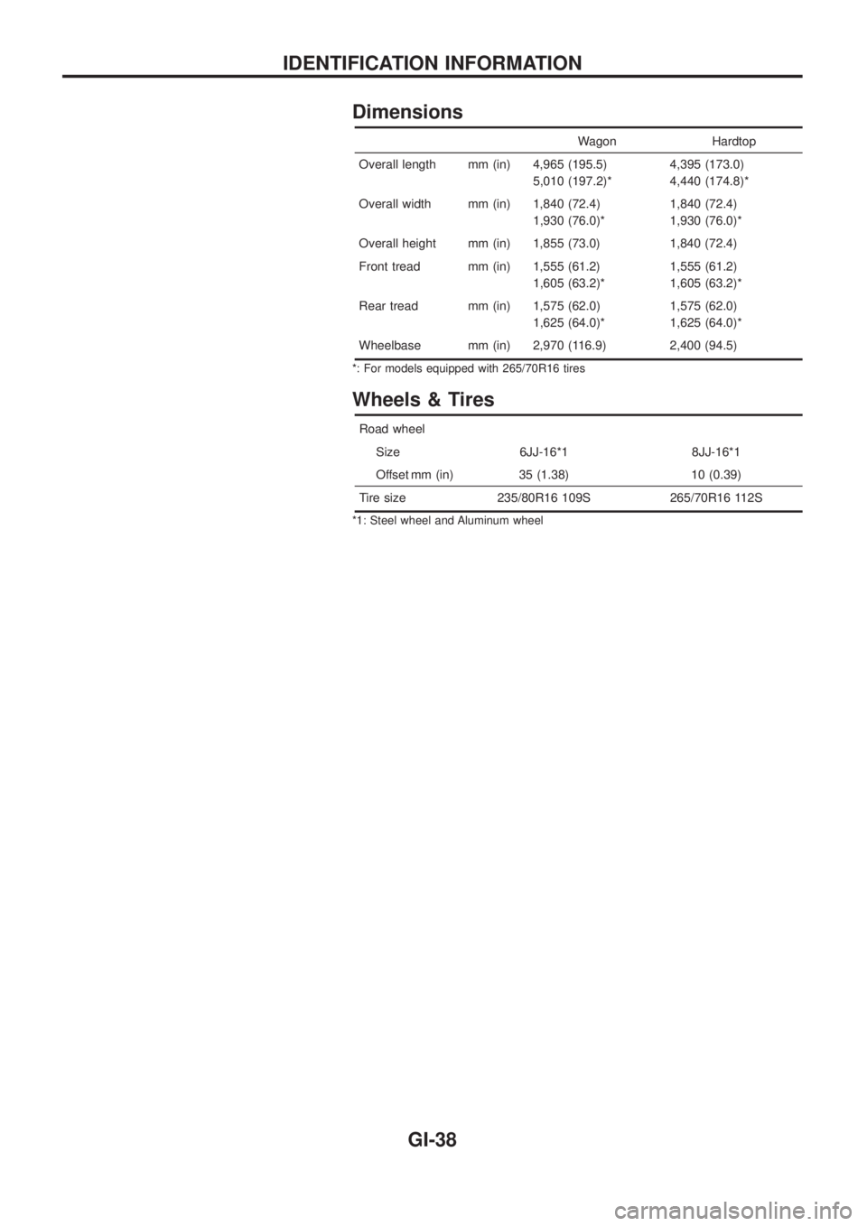
Dimensions
Wagon Hardtop
Overall length mm (in) 4,965 (195.5)
5,010 (197.2)*4,395 (173.0)
4,440 (174.8)*
Overall width mm (in) 1,840 (72.4)
1,930 (76.0)*1,840 (72.4)
1,930 (76.0)*
Overall height mm (in) 1,855 (73.0) 1,840 (72.4)
Front tread mm (in) 1,555 (61.2)
1,605 (63.2)*1,555 (61.2)
1,605 (63.2)*
Rear tread mm (in) 1,575 (62.0)
1,625 (64.0)*1,575 (62.0)
1,625 (64.0)*
Wheelbase mm (in) 2,970 (116.9) 2,400 (94.5)
*: For models equipped with 265/70R16 tires
Wheels & Tires
Road wheel
Size 6JJ-16*1 8JJ-16*1
Offset mm (in) 35 (1.38) 10 (0.39)
Tire size 235/80R16 109S 265/70R16 112S
*1: Steel wheel and Aluminum wheel
IDENTIFICATION INFORMATION
GI-38