Page 975 of 1226
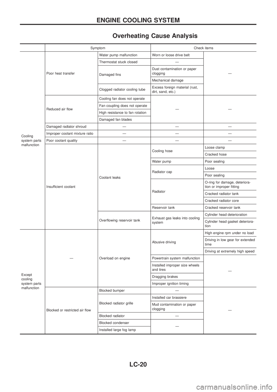
Overheating Cause Analysis
Symptom Check items
Cooling
system parts
malfunctionPoor heat transferWater pump malfunction Worn or loose drive belt
Ð Thermostat stuck closed Ð
Damaged ®nsDust contamination or paper
clogging
Mechanical damage
Clogged radiator cooling tubeExcess foreign material (rust,
dirt, sand, etc.)
Reduced air ¯owCooling fan does not operate
ÐÐ Fan coupling does not operate
High resistance to fan rotation
Damaged fan blades
Damaged radiator shroud Ð Ð Ð
Improper coolant mixture ratio Ð Ð Ð
Poor coolant quality Ð Ð Ð
Insufficient coolantCoolant leaksCooling hoseLoose clamp
Cracked hose
Water pump Poor sealing
Radiator capLoose
Poor sealing
RadiatorO-ring for damage, deteriora-
tion or improper ®tting
Cracked radiator tank
Cracked radiator core
Reservoir tank Cracked reservoir tank
Over¯owing reservoir tankExhaust gas leaks into cooling
systemCylinder head deterioration
Cylinder head gasket deteriora-
tion
Except
cooling
system parts
malfunctionÐ Overload on engineAbusive drivingHigh engine rpm under no load
Driving in low gear for extended
time
Driving at extremely high speed
Powertrain system malfunction
Ð Installed improper size wheels
and tires
Dragging brakes
Improper ignition timing
Blocked or restricted air ¯owBlocked bumper Ð
Ð Blocked radiator grilleInstalled car brassiere
Mud contamination or paper
clogging
Blocked radiator Ð
Blocked condenser
Ð
Installed large fog lamp
ENGINE COOLING SYSTEM
LC-20
Page 980 of 1226
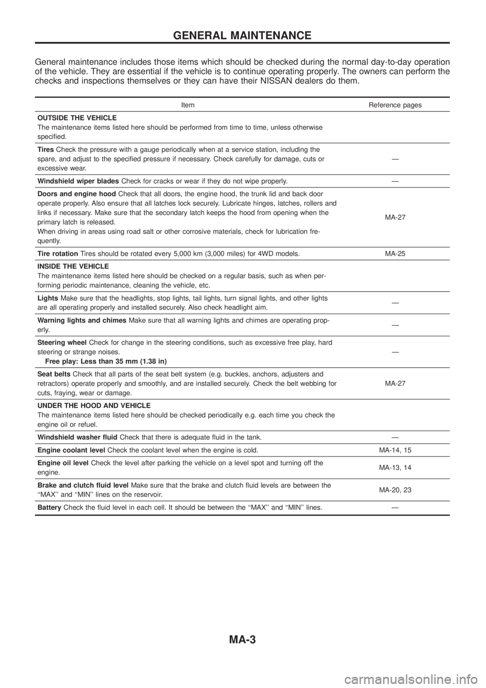
General maintenance includes those items which should be checked during the normal day-to-day operation
of the vehicle. They are essential if the vehicle is to continue operating properly. The owners can perform the
checks and inspections themselves or they can have their NISSAN dealers do them.
Item Reference pages
OUTSIDE THE VEHICLE
The maintenance items listed here should be performed from time to time, unless otherwise
speci®ed.
TiresCheck the pressure with a gauge periodically when at a service station, including the
spare, and adjust to the speci®ed pressure if necessary. Check carefully for damage, cuts or
excessive wear.Ð
Windshield wiper bladesCheck for cracks or wear if they do not wipe properly. Ð
Doors and engine hoodCheck that all doors, the engine hood, the trunk lid and back door
operate properly. Also ensure that all latches lock securely. Lubricate hinges, latches, rollers and
links if necessary. Make sure that the secondary latch keeps the hood from opening when the
primary latch is released.
When driving in areas using road salt or other corrosive materials, check for lubrication fre-
quently.MA-27
Tire rotationTires should be rotated every 5,000 km (3,000 miles) for 4WD models. MA-25
INSIDE THE VEHICLE
The maintenance items listed here should be checked on a regular basis, such as when per-
forming periodic maintenance, cleaning the vehicle, etc.
LightsMake sure that the headlights, stop lights, tail lights, turn signal lights, and other lights
are all operating properly and installed securely. Also check headlight aim.Ð
Warning lights and chimesMake sure that all warning lights and chimes are operating prop-
erly.Ð
Steering wheelCheck for change in the steering conditions, such as excessive free play, hard
steering or strange noises.
Free play: Less than 35 mm (1.38 in)Ð
Seat beltsCheck that all parts of the seat belt system (e.g. buckles, anchors, adjusters and
retractors) operate properly and smoothly, and are installed securely. Check the belt webbing for
cuts, fraying, wear or damage.MA-27
UNDER THE HOOD AND VEHICLE
The maintenance items listed here should be checked periodically e.g. each time you check the
engine oil or refuel.
Windshield washer ¯uidCheck that there is adequate ¯uid in the tank. Ð
Engine coolant levelCheck the coolant level when the engine is cold. MA-14, 15
Engine oil levelCheck the level after parking the vehicle on a level spot and turning off the
engine.MA-13, 14
Brake and clutch ¯uid levelMake sure that the brake and clutch ¯uid levels are between the
``MAX'' and ``MIN'' lines on the reservoir.MA-20, 23
BatteryCheck the ¯uid level in each cell. It should be between the ``MAX'' and ``MIN'' lines. Ð
GENERAL MAINTENANCE
MA-3
Page 1046 of 1226
NVH Troubleshooting Chart
Use the chart below to help you ®nd the cause of the symptom. If necessary, repair or replace these parts.
Reference pageÐ
Ð
PD-6
PD-6
PD-19
PD-29
PD-19
PD-14
Ð
Refer to MA section.
Refer to PROPELLER SHAFT in this chart.
Refer to DIFFERENTIAL in this chart.
NVH in FA, RA section
NVH in FA section
NVH in FA section
NVH in RA section
NVH in BR section
NVH in ST section
Possible cause and
SUSPECTED PARTS
Uneven rotation torque
Excessive joint angle
Rotation imbalance
Excessive runout
Rough gear tooth
Improper gear contact
Tooth surfaces worn
Incorrect backlash
Companion ¯ange excessive runout
Improper gear oil
PROPELLER SHAFT
DIFFERENTIAL
AXLE AND SUSPENSION
TIRES
ROAD WHEEL
DRIVE SHAFT
BRAKES
STEERING
SymptomPRO-
PELLER
SHAFTNoiseXXXX XXXXXXX
Shake XXXXXXX
VibrationXXXX XX X X
DIFFER-
ENTIALNoiseXXXXXXX XXXXXX
X: Applicable
NOISE, VIBRATION AND HARSHNESS (NVH) TROUBLESHOOTING
PD-4
Page 1097 of 1226
Precautions
+When installing rubber parts, ®nal tightening must be car-
ried out under unladen condition* with tires on ground.
*: Fuel, radiator coolant and engine oil full. Spare tire, jack,
hand tools and mats in designated positions.
+Use ¯are nut wrench when removing and installing brake
tubes.
+After installing removed suspension parts, check wheel
alignment and adjust if necessary.
+Always torque brake lines when installing.
Special Service Tools
Tool number
Tool nameDescription
KV40101000
Axle stand
NT159
Removing rear axle shaft
ST36230000
Sliding hammer
NT126
Removing rear axle shaft
ST38080001
Bearing lock nut wrench
NT507
Removing wheel bearing lock nut
a: 58 mm (2.28 in)
KV40106500
Wheel bearing puller
NT724
Removing wheel bearing
GG94310000
Flare nut torque
wrench
NT406
Removing and installing brake piping
a: 10 mm (0.39 in)
SBR820BA
PRECAUTIONS AND PREPARATION
RA-1
Page 1099 of 1226
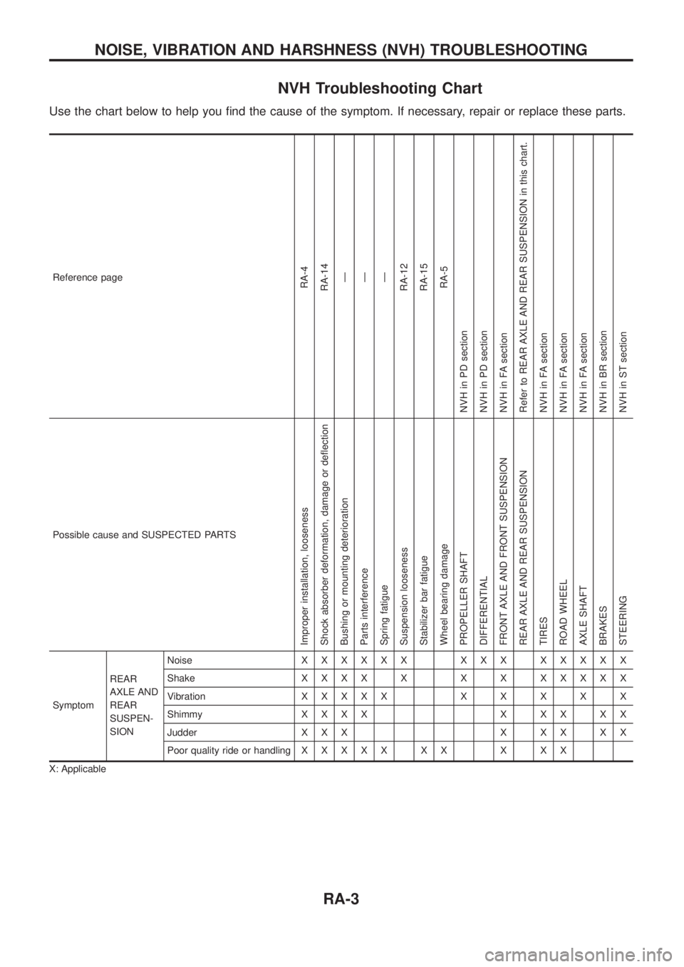
NVH Troubleshooting Chart
Use the chart below to help you ®nd the cause of the symptom. If necessary, repair or replace these parts.
Reference pageRA-4
RA-14
Ð
Ð
Ð
RA-12
RA-15
RA-5
NVH in PD section
NVH in PD section
NVH in FA section
Refer to REAR AXLE AND REAR SUSPENSION in this chart.
NVH in FA section
NVH in FA section
NVH in FA section
NVH in BR section
NVH in ST section
Possible cause and SUSPECTED PARTS
Improper installation, looseness
Shock absorber deformation, damage or de¯ection
Bushing or mounting deterioration
Parts interference
Spring fatigue
Suspension looseness
Stabilizer bar fatigue
Wheel bearing damage
PROPELLER SHAFT
DIFFERENTIAL
FRONT AXLE AND FRONT SUSPENSION
REAR AXLE AND REAR SUSPENSION
TIRES
ROAD WHEEL
AXLE SHAFT
BRAKES
STEERING
SymptomREAR
AXLE AND
REAR
SUSPEN-
SIONNoiseXXXXXX XXX XXXXX
ShakeXXXX X X X XXXXX
VibrationXXXXXXXXXX
ShimmyXXXX X XX XX
Judder X X X X X X X X
Poor quality ride or handlingXXXXX XX X XX
X: Applicable
NOISE, VIBRATION AND HARSHNESS (NVH) TROUBLESHOOTING
RA-3
Page 1110 of 1226
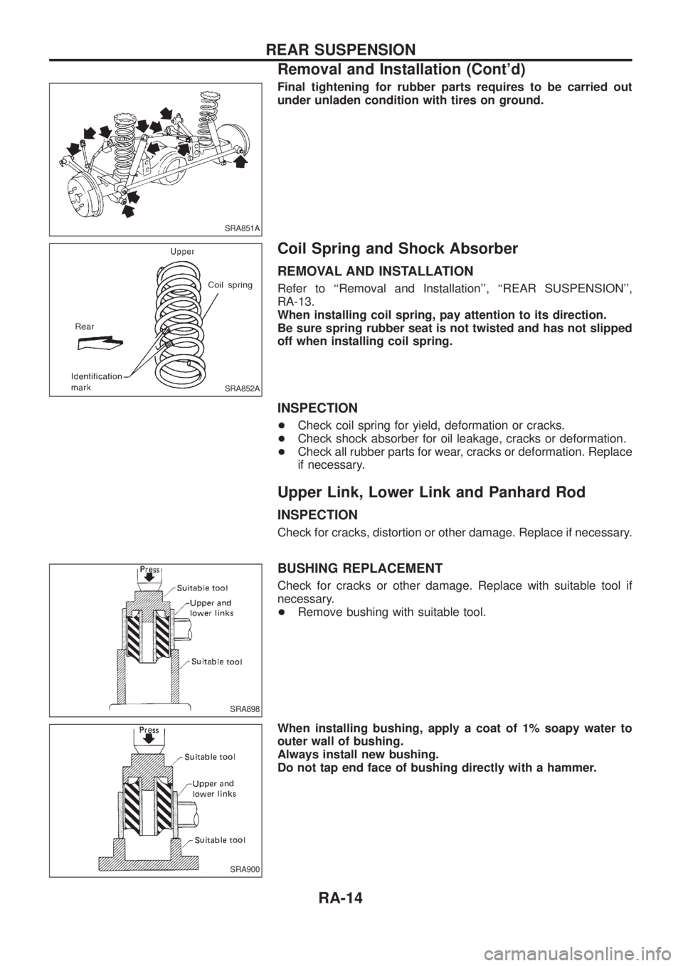
Final tightening for rubber parts requires to be carried out
under unladen condition with tires on ground.
Coil Spring and Shock Absorber
REMOVAL AND INSTALLATION
Refer to ``Removal and Installation'', ``REAR SUSPENSION'',
RA-13.
When installing coil spring, pay attention to its direction.
Be sure spring rubber seat is not twisted and has not slipped
off when installing coil spring.
INSPECTION
+Check coil spring for yield, deformation or cracks.
+Check shock absorber for oil leakage, cracks or deformation.
+Check all rubber parts for wear, cracks or deformation. Replace
if necessary.
Upper Link, Lower Link and Panhard Rod
INSPECTION
Check for cracks, distortion or other damage. Replace if necessary.
BUSHING REPLACEMENT
Check for cracks or other damage. Replace with suitable tool if
necessary.
+Remove bushing with suitable tool.
When installing bushing, apply a coat of 1% soapy water to
outer wall of bushing.
Always install new bushing.
Do not tap end face of bushing directly with a hammer.
SRA851A
SRA852A
SRA898
SRA900
REAR SUSPENSION
Removal and Installation (Cont'd)
RA-14
Page 1111 of 1226
INSTALLATION
When installing each link, pay attention to direction of nuts
and bolts.
When installing each rubber part, ®nal tightening must be car-
ried out under unladen condition with tires on ground.
Stabilizer Bar
REMOVAL AND INSTALLATION
+When removing and installing stabilizer bar, ®x portion A.
+Install stabilizer bar with ball joint socket properly placed.
SRA766A
SFA449BA
REAR SUSPENSION
Upper Link, Lower Link and Panhard Rod
(Cont'd)
RA-15
Page 1172 of 1226
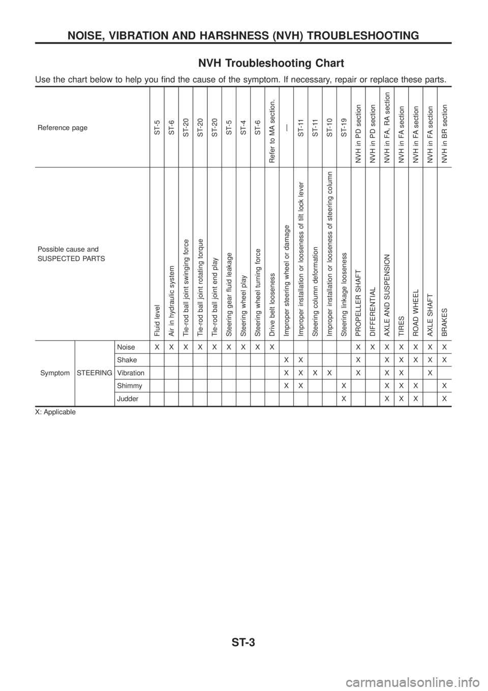
NVH Troubleshooting Chart
Use the chart below to help you ®nd the cause of the symptom. If necessary, repair or replace these parts.
Reference pageST-5
ST-6
ST-20
ST-20
ST-20
ST-5
ST-4
ST-6
Refer to MA section.
Ð
ST-11
ST-11
ST-10
ST-19
NVH in PD section
NVH in PD section
NVH in FA, RA section
NVH in FA section
NVH in FA section
NVH in FA section
NVH in BR section
Possible cause and
SUSPECTED PARTS
Fluid level
Air in hydraulic system
Tie-rod ball joint swinging force
Tie-rod ball joint rotating torque
Tie-rod ball joint end play
Steering gear ¯uid leakage
Steering wheel play
Steering wheel turning force
Drive belt looseness
Improper steering wheel or damage
Improper installation or looseness of tilt lock lever
Steering column deformation
Improper installation or looseness of steering column
Steering linkage looseness
PROPELLER SHAFT
DIFFERENTIAL
AXLE AND SUSPENSION
TIRES
ROAD WHEEL
AXLE SHAFT
BRAKES
Symptom STEERINGNoiseXXXXXXXXX XXXXXXX
Shake X X XXXXXX
VibrationXXXXXXXX
Shimmy X X X X X X X
Judder X X X X X
X: Applicable
NOISE, VIBRATION AND HARSHNESS (NVH) TROUBLESHOOTING
ST-3