2006 NISSAN PATROL brake pads
[x] Cancel search: brake padsPage 6 of 1226
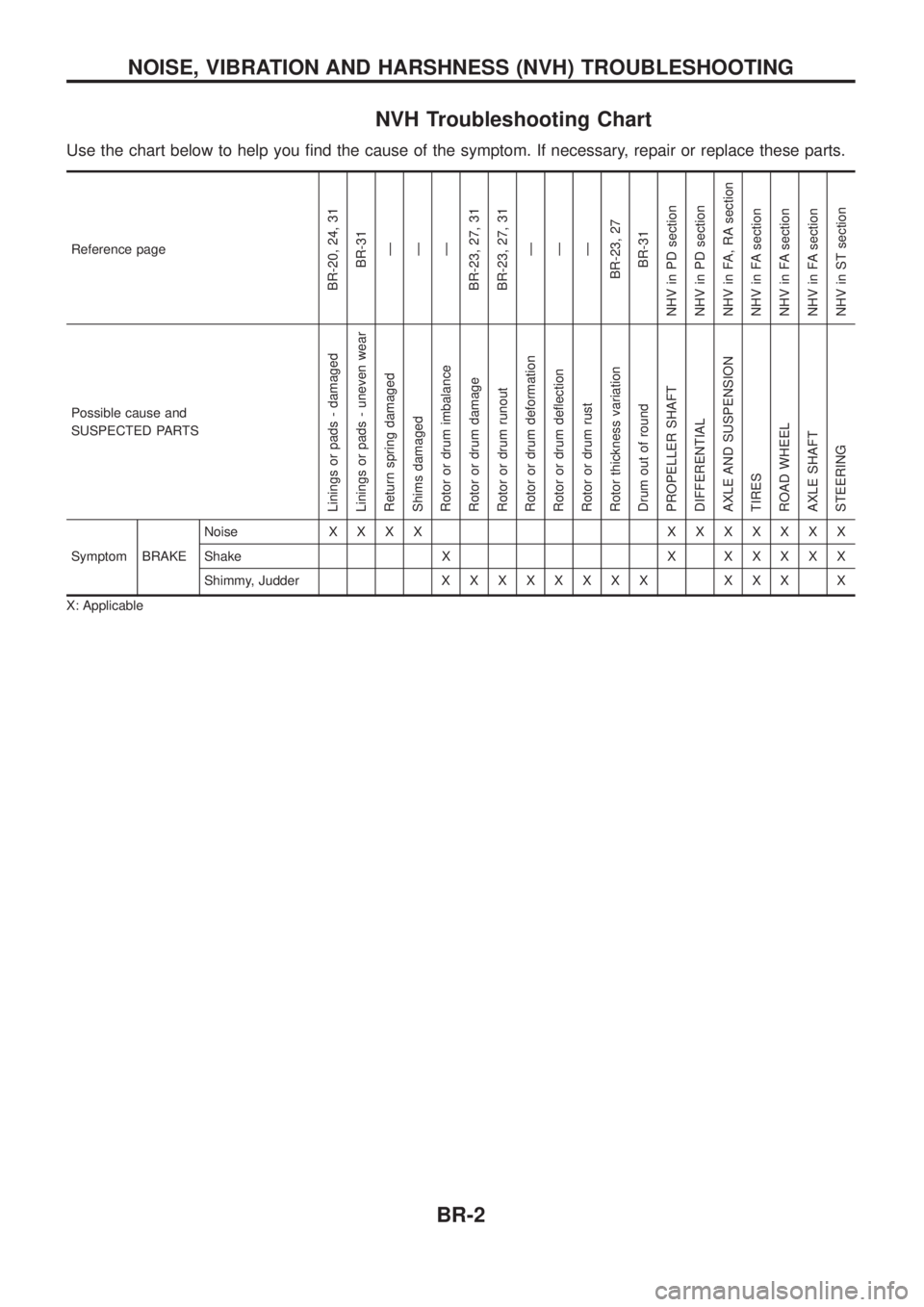
NVH Troubleshooting Chart
Use the chart below to help you ®nd the cause of the symptom. If necessary, repair or replace these parts.
Reference page
BR-20, 24, 31BR-31Ð
Ð
Ð
BR-23, 27, 31
BR-23, 27, 31 Ð
Ð
Ð
BR-23, 27 BR-31
NHV in PD section
NHV in PD section
NHV in FA, RA section
NHV in FA section
NHV in FA section
NHV in FA section
NHV in ST section
Possible cause and
SUSPECTED PARTS
Linings or pads - damaged
Linings or pads - uneven wear
Return spring damaged
Shims damaged
Rotor or drum imbalance
Rotor or drum damage
Rotor or drum runout
Rotor or drum deformation
Rotor or drum de¯ection
Rotor or drum rust
Rotor thickness variation
Drum out of round
PROPELLER SHAFT
DIFFERENTIAL
AXLE AND SUSPENSION
TIRES
ROAD WHEEL
AXLE SHAFT
STEERING
Symptom BRAKE Noise
XXXX XXXXXXX
Shake X X X X X X X
Shimmy, Judder X X XXXXXX XXX X
X: Applicable
NOISE, VIBRATION AND HARSHNESS (NVH) TROUBLESHOOTING
BR-2
Page 25 of 1226
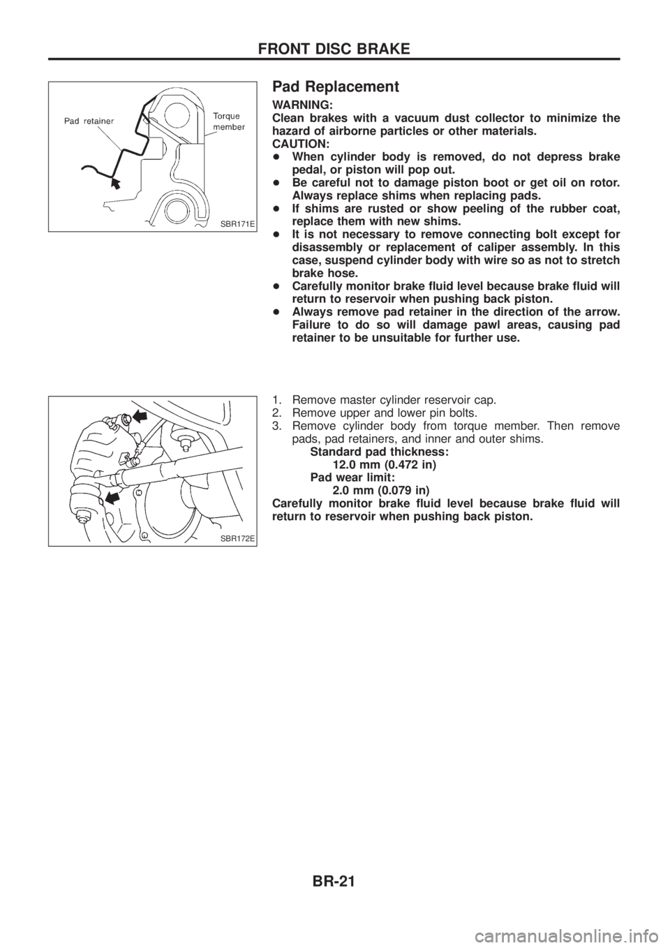
Pad Replacement
WARNING:
Clean brakes with a vacuum dust collector to minimize the
hazard of airborne particles or other materials.
CAUTION:
+When cylinder body is removed, do not depress brake
pedal, or piston will pop out.
+ Be careful not to damage piston boot or get oil on rotor.
Always replace shims when replacing pads.
+ If shims are rusted or show peeling of the rubber coat,
replace them with new shims.
+ It is not necessary to remove connecting bolt except for
disassembly or replacement of caliper assembly. In this
case, suspend cylinder body with wire so as not to stretch
brake hose.
+ Carefully monitor brake ¯uid level because brake ¯uid will
return to reservoir when pushing back piston.
+ Always remove pad retainer in the direction of the arrow.
Failure to do so will damage pawl areas, causing pad
retainer to be unsuitable for further use.
1. Remove master cylinder reservoir cap.
2. Remove upper and lower pin bolts.
3. Remove cylinder body from torque member. Then remove pads, pad retainers, and inner and outer shims.Standard pad thickness: 12.0 mm (0.472 in)
Pad wear limit: 2.0 mm (0.079 in)
Carefully monitor brake ¯uid level because brake ¯uid will
return to reservoir when pushing back piston.
SBR171E
SBR172E
FRONT DISC BRAKE
BR-21
Page 27 of 1226
Removal
WARNING:
Clean brake pads with a vacuum dust collector to minimize the
hazard of airborne particles or other materials.
CAUTION:
Suspend caliper assembly with wire so as not to stretch brake
hose.
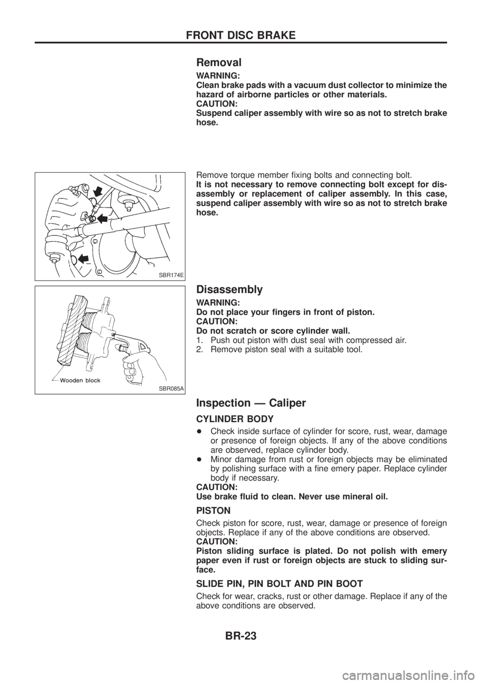
Remove torque member ®xing bolts and connecting bolt.
It is not necessary to remove connecting bolt except for dis-
assembly or replacement of caliper assembly. In this case,
suspend caliper assembly with wire so as not to stretch brake
hose.
Disassembly
WARNING:
Do not place your ®ngers in front of piston.
CAUTION:
Do not scratch or score cylinder wall.
1. Push out piston with dust seal with compressed air.
2. Remove piston seal with a suitable tool.
Inspection Ð Caliper
CYLINDER BODY
+Check inside surface of cylinder for score, rust, wear, damage
or presence of foreign objects. If any of the above conditions
are observed, replace cylinder body.
+ Minor damage from rust or foreign objects may be eliminated
by polishing surface with a ®ne emery paper. Replace cylinder
body if necessary.
CAUTION:
Use brake ¯uid to clean. Never use mineral oil.
PISTON
Check piston for score, rust, wear, damage or presence of foreign
objects. Replace if any of the above conditions are observed.
CAUTION:
Piston sliding surface is plated. Do not polish with emery
paper even if rust or foreign objects are stuck to sliding sur-
face.
SLIDE PIN, PIN BOLT AND PIN BOOT
Check for wear, cracks, rust or other damage. Replace if any of the
above conditions are observed.
SBR174E
SBR085A
FRONT DISC BRAKE
BR-23
Page 29 of 1226
Pad Replacement
WARNING:
Clean brakes with a vacuum dust collector to minimize the
hazard of airborne particles or other materials.
CAUTION:
+When cylinder body is open, do not depress brake pedal,
or piston will pop out.
+ Be careful not to damage piston boot or get oil on rotor.
Always replace shims when replacing pads.
+ If shims are rusted or show peeling of the rubber coat,
replace them with new shims.
+ It is not necessary to remove connecting bolt except for
disassembly or replacement of caliper assembly. In this
case, suspend cylinder body with wire so as not to stretch
brake hose.
+ Carefully monitor brake ¯uid level because brake ¯uid will
return to reservoir when pushing back piston.
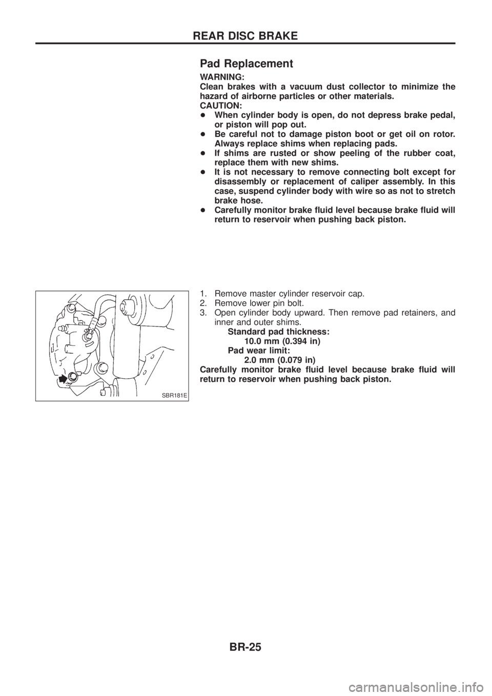
1. Remove master cylinder reservoir cap.
2. Remove lower pin bolt.
3. Open cylinder body upward. Then remove pad retainers, and inner and outer shims.Standard pad thickness: 10.0 mm (0.394 in)
Pad wear limit: 2.0 mm (0.079 in)
Carefully monitor brake ¯uid level because brake ¯uid will
return to reservoir when pushing back piston.
SBR181E
REAR DISC BRAKE
BR-25
Page 31 of 1226
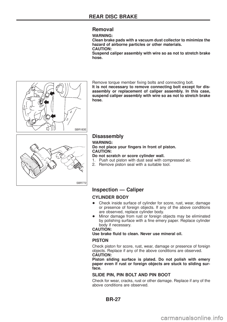
Removal
WARNING:
Clean brake pads with a vacuum dust collector to minimize the
hazard of airborne particles or other materials.
CAUTION:
Suspend caliper assembly with wire so as not to stretch brake
hose.
Remove torque member ®xing bolts and connecting bolt.
It is not necessary to remove connecting bolt except for dis-
assembly or replacement of caliper assembly. In this case,
suspend caliper assembly with wire so as not to stretch brake
hose.
Disassembly
WARNING:
Do not place your ®ngers in front of piston.
CAUTION:
Do not scratch or score cylinder wall.
1. Push out piston with dust seal with compressed air.
2. Remove piston seal with a suitable tool.
Inspection Ð Caliper
CYLINDER BODY
+Check inside surface of cylinder for score, rust, wear, damage
or presence of foreign objects. If any of the above conditions
are observed, replace cylinder body.
+ Minor damage from rust or foreign objects may be eliminated
by polishing surface with a ®ne emery paper. Replace cylinder
body if necessary.
CAUTION:
Use brake ¯uid to clean. Never use mineral oil.
PISTON
Check piston for score, rust, wear, damage or presence of foreign
objects. Replace if any of the above conditions are observed.
CAUTION:
Piston sliding surface is plated. Do not polish with emery
paper even if rust or foreign objects are stuck to sliding sur-
face.
SLIDE PIN, PIN BOLT AND PIN BOOT
Check for wear, cracks, rust or other damage. Replace if any of the
above conditions are observed.
SBR183E
SBR772
REAR DISC BRAKE
BR-27
Page 44 of 1226

Preliminary Check
Check brake ¯uid level in reservoir
tank.
- ---------------------------------------------------------------------------------------------------------------------------------------------------------------------------------------------------------------------------------------------------------------------------------------------------------------
Low ¯uid level may indicate brake pad
wear or leakage from brake line.
Check brake line for leakage.
OKcNG Repair.
b
Check brake booster for operation and air
tightness. Refer to BR-15.
OK
cNGReplace.
b
Check brake pads and rotor. Refer to
BR-21, 25.
OK
cNGReplace.
Check brake ¯uid level in reservoir tank
again.
OK
cNGFill up brake ¯uid.
Check warning lamp activation.
When ignition switch is turned on, warning
lamp turns on.
OK
cNG
Check fuse, warning lamp
bulb and warning lamp cir-
cuit.
Check warning lamp for deactivation after
engine is started.
OK
cNGGo to Self-diagnosis,
BR-46, 50.
Drive vehicle at speeds over 30 km/h (19
MPH) for at least 1 minute.
Ensure warning lamp remains off while
driving.
OK
cNGGo to Self-diagnosis,
BR-46, 50.
END
SBR451D
SBR389C
SBR058C
SBR059C
SBR186E
.
.
.
.
.
.
.
.
.
TROUBLE DIAGNOSES
BR-40
Page 983 of 1226
![NISSAN PATROL 2006 Service Manual Chassis and Body Services
Annual driving distance below 30,000 km (18,000 miles)
Abbreviations: R = Replace, I = Inspect, and correct or replace as necessary, L = Lubricate,T=Tighten.
[ ]: At the spec NISSAN PATROL 2006 Service Manual Chassis and Body Services
Annual driving distance below 30,000 km (18,000 miles)
Abbreviations: R = Replace, I = Inspect, and correct or replace as necessary, L = Lubricate,T=Tighten.
[ ]: At the spec](/manual-img/5/57368/w960_57368-982.png)
Chassis and Body Services
Annual driving distance below 30,000 km (18,000 miles)
Abbreviations: R = Replace, I = Inspect, and correct or replace as necessary, L = Lubricate,T=Tighten.
[ ]: At the speci®ed mileage only
MAINTENANCE OPERATIONMAINTENANCE INTERVAL
Reference
page Perform either at number of kilometers (miles) or months,
whichever comes ®rst.km x 1,000 10 20 30 40 50 60 70 80 90
(Miles x 1,000) (6) (12) (18) (24) (30) (36) (42) (48) (54)
Months 6 12 18 24 30 36 42 48 54
CHASSIS AND BODY Underhood and under vehicle
Brake & clutch ¯uid (For level & leaks).I I I I MA-23, 20
Brake ¯uid.R R MA-24
Brake booster vacuum hoses, connections & check valve I I MA-24
Power steering ¯uid & lines (For level & leaks) I I I I MA-26
Brake & clutch systemsI I I I MA-24, 20
Manual transmission oil (For leaks) I I I I MA-20
Manual transmission oil[R] MA-20
Transfer ¯uidI I R I MA-21
Limited slip differential (LSD) gear oil (For level & leaks).*1 I I R I MA-22
Steering gear & linkage, axle & suspension parts, propeller shaft & exhaust system.I I I I MA-26, 20 *2
Greasing points of propeller shaftLLLLMA-21
Drive shafts & steering damper.IIII *3
Body mounting bolts & nutsTTTT *4
Outside and Inside
Wheel alignment (If necessary, rotate & balance wheels) I I I I MA-25, *5
Brake pads, discs & other brake components.I I I I MA-24
Front wheel bearing grease I R I R MA-22
Axle joint in knuckle ¯angeL L MA-23
Free running hub greaseI I I I MA-23
Headlamp aimingIIII *6
Foot brake, parking brake & clutch (For free play, stroke & operation) I I I I *7
Ventilation air ®lterRRR*8
Body corrosionAnnually MA-28
Air bag systemSee NOTE (1) *9
NOTE: (1) Inspect after 10 years, then every 2 years.
(2) Maintenance items with ``.'' should be performed more frequently according to ``Maintenance Under Severe Driv-
ing Conditions''.
*1: Including differential gear with differential lock
*2: ``Front Axle and Front Suspension Parts'' in FA section, ``Rear Axle and Rear Suspension Parts'' in RA section
*3: ``FRONT AXLE Ð Drive Shaft'' in FA section
*4: ``CAB BODY'' in BT section
*5: ``Front Wheel Alignment'' in FA section
*6: ``Aiming Adjustment'' in EL section
*7: ``Brake Pedal and Bracket'' in BR section, ``Adjusting Clutch Pedal'' in CL section
*8: ``Ventilation air ®lter'' in HA section
*9: ``Maintenance Items'' in RS section
PERIODIC MAINTENANCE
MA-6
Page 984 of 1226
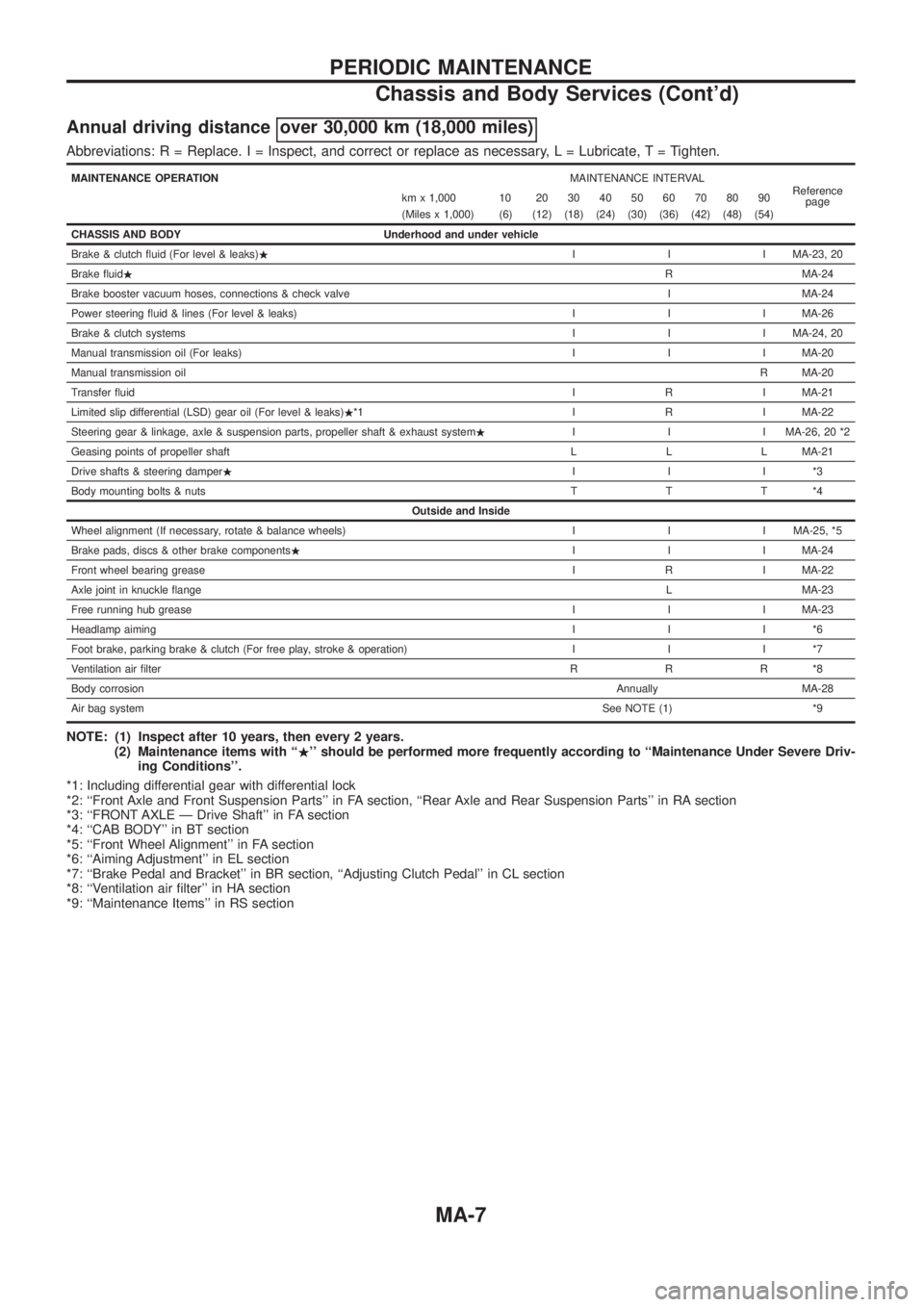
Annual driving distance over 30,000 km (18,000 miles)
Abbreviations: R = Replace. I = Inspect, and correct or replace as necessary, L = Lubricate,T=Tighten.
MAINTENANCE OPERATIONMAINTENANCE INTERVAL
Reference
page km x 1,000 10 20 30 40 50 60 70 80 90
(Miles x 1,000) (6) (12) (18) (24) (30) (36) (42) (48) (54)
CHASSIS AND BODY Underhood and under vehicle
Brake & clutch ¯uid (For level & leaks).I I I MA-23, 20
Brake ¯uid.R MA-24
Brake booster vacuum hoses, connections & check valve I MA-24
Power steering ¯uid & lines (For level & leaks) I I I MA-26
Brake & clutch systemsI I I MA-24, 20
Manual transmission oil (For leaks) I I I MA-20
Manual transmission oilR MA-20
Transfer ¯uidI R I MA-21
Limited slip differential (LSD) gear oil (For level & leaks).*1 I R I MA-22
Steering gear & linkage, axle & suspension parts, propeller shaft & exhaust system.I I I MA-26, 20 *2
Geasing points of propeller shaft L L L MA-21
Drive shafts & steering damper.III*3
Body mounting bolts & nutsTTT*4
Outside and Inside
Wheel alignment (If necessary, rotate & balance wheels) I I I MA-25, *5
Brake pads, discs & other brake components.I I I MA-24
Front wheel bearing greaseI R I MA-22
Axle joint in knuckle ¯angeL MA-23
Free running hub greaseI I I MA-23
Headlamp aimingIII*6
Foot brake, parking brake & clutch (For free play, stroke & operation) I I I *7
Ventilation air ®lterRRR*8
Body corrosionAnnually MA-28
Air bag systemSee NOTE (1) *9
NOTE: (1) Inspect after 10 years, then every 2 years.
(2) Maintenance items with ``.'' should be performed more frequently according to ``Maintenance Under Severe Driv-
ing Conditions''.
*1: Including differential gear with differential lock
*2: ``Front Axle and Front Suspension Parts'' in FA section, ``Rear Axle and Rear Suspension Parts'' in RA section
*3: ``FRONT AXLE Ð Drive Shaft'' in FA section
*4: ``CAB BODY'' in BT section
*5: ``Front Wheel Alignment'' in FA section
*6: ``Aiming Adjustment'' in EL section
*7: ``Brake Pedal and Bracket'' in BR section, ``Adjusting Clutch Pedal'' in CL section
*8: ``Ventilation air ®lter'' in HA section
*9: ``Maintenance Items'' in RS section
PERIODIC MAINTENANCE
Chassis and Body Services (Cont'd)
MA-7