2006 NISSAN PATROL tire pressure
[x] Cancel search: tire pressurePage 11 of 1226

1. Ensure vehicle is unladen condition*.* Fuel, radiator coolant and engine oil full. Spare tire, jack,hand tools and mats in designated positions.
2. Have a driver sit in the driver's seat and one person sit on the rear end. Then have the person on the rear end slowly get off
the vehicle. This is necessary to stabilize suspension de¯ec-
tion.
3. Gradually depress brake pedal and attach a lever to the stop- per bolt, then adjust length ``L'' as follows:Length ``L'': Approx. 175.2 - 178.2 mm (6.90 - 7.02 in)
4. Remove front LH tire.
5. Connect tool to air bleeders on front LH brake caliper and rear LH or RH brake wheel cylinder.
6. Install front LH tire.
Before installing front LH tire, con®rm the tool is not touching
the front LH wheel.
7. Bleed air from Tool.
8. Raise front brake pressure to 4,904 kPa (49.0 bar, 50 kg/cm
2,
711 psi) and 9,807 kPa (98.1 bar, 100 kg/cm2, 1,422 psi) and
check rear brake pressure. Rear brake pressure: Refer to table on next page.
SBR287E
SBR822BA
SBR823BA
SBR377D
BRAKE HYDRAULIC LINE/CONTROL VALVE
Load Sensing Valve (Cont'd)
BR-7
Page 12 of 1226
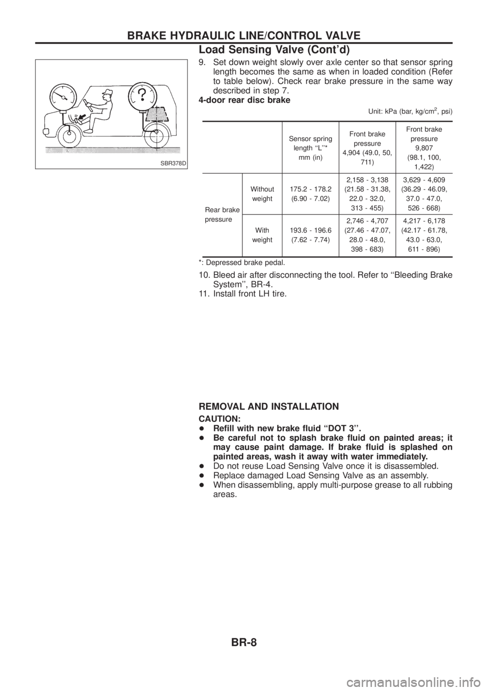
9. Set down weight slowly over axle center so that sensor springlength becomes the same as when in loaded condition (Refer
to table below). Check rear brake pressure in the same way
described in step 7.
4-door rear disc brake
Unit: kPa (bar, kg/cm2, psi)
Sensor spring
length ``L''* mm (in) Front brake
pressure
4,904 (49.0, 50, 711) Front brake
pressure 9,807
(98.1, 100, 1,422)
Rear brake
pressure Without
weight 175.2 - 178.2
(6.90 - 7.02) 2,158 - 3,138
(21.58 - 31.38, 22.0 - 32.0,313 - 455) 3,629 - 4,609
(36.29 - 46.09, 37.0 - 47.0,526 - 668)
With
weight 193.6 - 196.6
(7.62 - 7.74) 2,746 - 4,707
(27.46 - 47.07, 28.0 - 48.0,398 - 683) 4,217 - 6,178
(42.17 - 61.78, 43.0 - 63.0,611 - 896)
*: Depressed brake pedal.
10. Bleed air after disconnecting the tool. Refer to ``Bleeding Brake System'', BR-4.
11. Install front LH tire.
REMOVAL AND INSTALLATION
CAUTION:
+ Re®ll with new brake ¯uid ``DOT 3''.
+ Be careful not to splash brake ¯uid on painted areas; it
may cause paint damage. If brake ¯uid is splashed on
painted areas, wash it away with water immediately.
+ Do not reuse Load Sensing Valve once it is disassembled.
+ Replace damaged Load Sensing Valve as an assembly.
+ When disassembling, apply multi-purpose grease to all rubbing
areas.
SBR378D
BRAKE HYDRAULIC LINE/CONTROL VALVE
Load Sensing Valve (Cont'd)
BR-8
Page 62 of 1226
jA
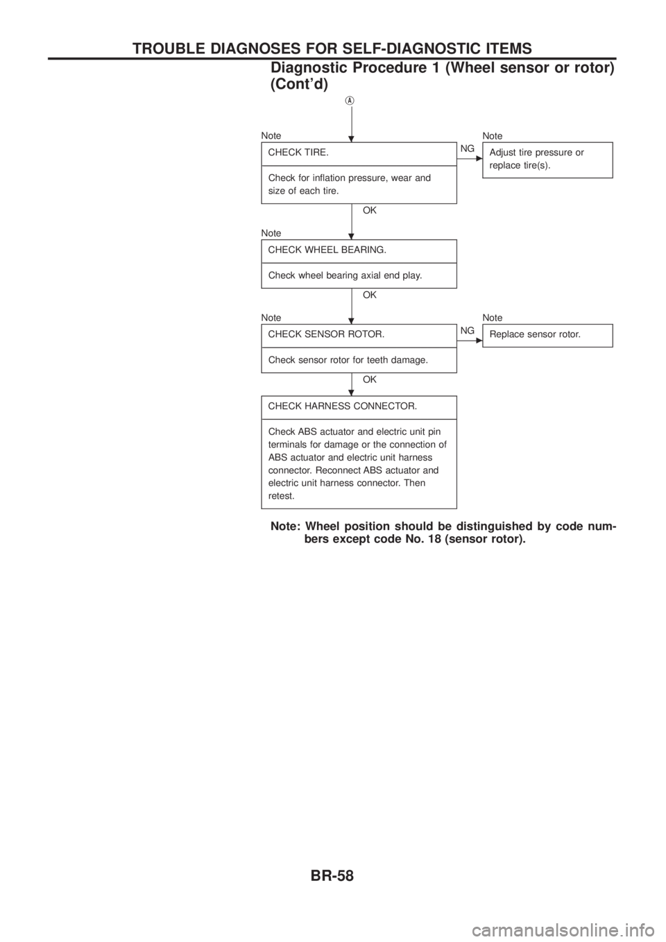
NoteCHECK TIRE.
- ---------------------------------------------------------------------------------------------------------------------------------------------------------------------------------------------------------------------------------------------------------------------------------------------------------------
Check for in¯ation pressure, wear and
size of each tire.
OK
cNG Note
Adjust tire pressure or
replace tire(s).
NoteCHECK WHEEL BEARING.
- ---------------------------------------------------------------------------------------------------------------------------------------------------------------------------------------------------------------------------------------------------------------------------------------------------------------
Check wheel bearing axial end play.
OK
Note CHECK SENSOR ROTOR.
- ---------------------------------------------------------------------------------------------------------------------------------------------------------------------------------------------------------------------------------------------------------------------------------------------------------------
Check sensor rotor for teeth damage.
OK
cNG Note
Replace sensor rotor.
CHECK HARNESS CONNECTOR.
- ---------------------------------------------------------------------------------------------------------------------------------------------------------------------------------------------------------------------------------------------------------------------------------------------------------------
Check ABS actuator and electric unit pin
terminals for damage or the connection of
ABS actuator and electric unit harness
connector. Reconnect ABS actuator and
electric unit harness connector. Then
retest.
Note: Wheel position should be distinguished by code num- bers except code No. 18 (sensor rotor).
.
.
.
.
TROUBLE DIAGNOSES FOR SELF-DIAGNOSTIC ITEMS
Diagnostic Procedure 1 (Wheel sensor or rotor)
(Cont'd)
BR-58
Page 408 of 1226
Bulb Replacement
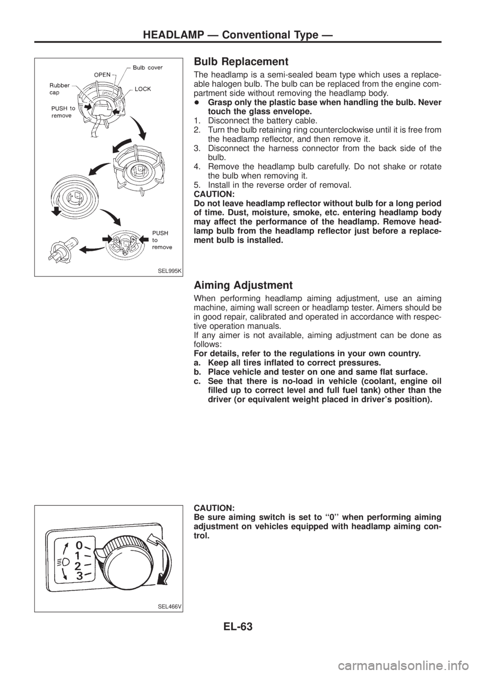
The headlamp is a semi-sealed beam type which uses a replace-
able halogen bulb. The bulb can be replaced from the engine com-
partment side without removing the headlamp body.
+Grasp only the plastic base when handling the bulb. Never
touch the glass envelope.
1. Disconnect the battery cable.
2. Turn the bulb retaining ring counterclockwise until it is free from
the headlamp re¯ector, and then remove it.
3. Disconnect the harness connector from the back side of the
bulb.
4. Remove the headlamp bulb carefully. Do not shake or rotate
the bulb when removing it.
5. Install in the reverse order of removal.
CAUTION:
Do not leave headlamp re¯ector without bulb for a long period
of time. Dust, moisture, smoke, etc. entering headlamp body
may affect the performance of the headlamp. Remove head-
lamp bulb from the headlamp re¯ector just before a replace-
ment bulb is installed.
Aiming Adjustment
When performing headlamp aiming adjustment, use an aiming
machine, aiming wall screen or headlamp tester. Aimers should be
in good repair, calibrated and operated in accordance with respec-
tive operation manuals.
If any aimer is not available, aiming adjustment can be done as
follows:
For details, refer to the regulations in your own country.
a. Keep all tires in¯ated to correct pressures.
b. Place vehicle and tester on one and same ¯at surface.
c. See that there is no-load in vehicle (coolant, engine oil
®lled up to correct level and full fuel tank) other than the
driver (or equivalent weight placed in driver's position).
CAUTION:
Be sure aiming switch is set to ``0'' when performing aiming
adjustment on vehicles equipped with headlamp aiming con-
trol.
SEL995K
SEL466V
HEADLAMP Ð Conventional Type Ð
EL-63
Page 736 of 1226
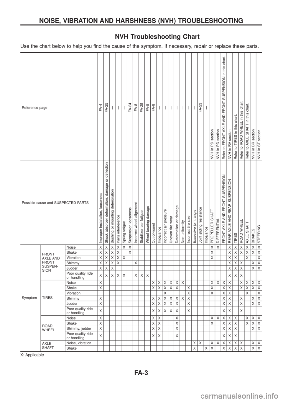
NVH Troubleshooting Chart
Use the chart below to help you ®nd the cause of the symptom. If necessary, repair or replace these parts.
Reference pageFA-4
FA-25
Ð
Ð
Ð
FA-24
FA-8
FA-25
FA-5
FA-8
Ð
Ð
Ð
Ð
Ð
Ð
Ð
FA-23
Ð
NVH in PD section
NVH in PD section
Refer to FRONT AXLE AND FRONT SUSPENSION in this chart.
NVH in RA section
Refer to TIRES in this chart.
Refer to ROAD WHEEL in this chart.
Refer to AXLE SHAFT in this chart.
NVH in BR section
NVH in ST section
Possible cause and SUSPECTED PARTS
Improper installation, looseness
Shock absorber deformation, damage or de¯ection
Bushing or mounting deterioration
Parts interference
Spring fatigue
Suspension looseness
Incorrect wheel alignment
Stabilizer bar fatigue
Wheel bearing damage
Out-of-round
Imbalance
Incorrect air pressure
Uneven tire wear
Deformation or damage
Non-uniformity
Incorrect tire size
Excessive joint angle
Joint sliding resistance
Imbalance
PROPELLER SHAFT
DIFFERENTIAL
FRONT AXLE AND FRONT SUSPENSION
REAR AXLE AND REAR SUSPENSION
TIRES
ROAD WHEEL
AXLE SHAFT
BRAKES
STEERING
SymptomFRONT
AXLE AND
FRONT
SUSPEN-
SIONNoiseXXXXXX XX XXXXXX
ShakeXXXX X X XXXXXX
VibrationXXXXX X XX X X
ShimmyXXXX X XXX XX
Judder X X XXXX XX
Poor quality ride
or handlingXXXXX XXX XXX
TIRESNoise XXXXXXX XXXX XXXX
Shake XXXXXX X X XX XXXX
Vibration X X X X X X X
Shimmy XXXXXXXX XX X XX
Judder XXXXXX X XX X XX
Poor quality ride
or handlingX XXXXX X XX X
ROAD
WHEELNoise X X X XXXXXX XXX
Shake X X X X X X X X X X X
Shimmy, judder X X X X X X X X X
Poor quality ride
or handlingX XX X XXX
AXLE
SHAFTNoise, vibration X XXXXXXX XX
ShakeX XX XXXX XX
X: Applicable
NOISE, VIBRATION AND HARSHNESS (NVH) TROUBLESHOOTING
FA-3
Page 979 of 1226
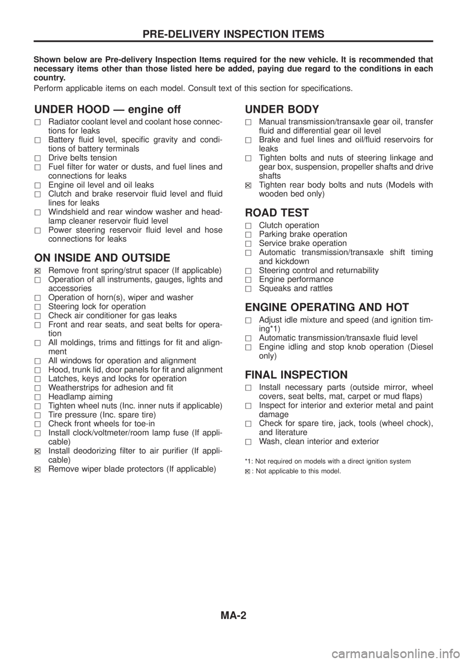
Shown below are Pre-delivery Inspection Items required for the new vehicle. It is recommended that
necessary items other than those listed here be added, paying due regard to the conditions in each
country.
Perform applicable items on each model. Consult text of this section for speci®cations.
UNDER HOOD Ð engine off
hRadiator coolant level and coolant hose connec-
tions for leaks
hBattery ¯uid level, speci®c gravity and condi-
tions of battery terminals
hDrive belts tension
hFuel ®lter for water or dusts, and fuel lines and
connections for leaks
hEngine oil level and oil leaks
hClutch and brake reservoir ¯uid level and ¯uid
lines for leaks
hWindshield and rear window washer and head-
lamp cleaner reservoir ¯uid level
hPower steering reservoir ¯uid level and hose
connections for leaks
ON INSIDE AND OUTSIDE
hXRemove front spring/strut spacer (If applicable)
hOperation of all instruments, gauges, lights and
accessories
hOperation of horn(s), wiper and washer
hSteering lock for operation
hCheck air conditioner for gas leaks
hFront and rear seats, and seat belts for opera-
tion
hAll moldings, trims and ®ttings for ®t and align-
ment
hAll windows for operation and alignment
hHood, trunk lid, door panels for ®t and alignment
hLatches, keys and locks for operation
hWeatherstrips for adhesion and ®t
hHeadlamp aiming
hTighten wheel nuts (Inc. inner nuts if applicable)
hTire pressure (Inc. spare tire)
hCheck front wheels for toe-in
hInstall clock/voltmeter/room lamp fuse (If appli-
cable)
h
XInstall deodorizing ®lter to air puri®er (If appli-
cable)
h
XRemove wiper blade protectors (If applicable)
UNDER BODY
hManual transmission/transaxle gear oil, transfer
¯uid and differential gear oil level
hBrake and fuel lines and oil/¯uid reservoirs for
leaks
hTighten bolts and nuts of steering linkage and
gear box, suspension, propeller shafts and drive
shafts
h
XTighten rear body bolts and nuts (Models with
wooden bed only)
ROAD TEST
hClutch operation
hParking brake operation
hService brake operation
hAutomatic transmission/transaxle shift timing
and kickdown
hSteering control and returnability
hEngine performance
hSqueaks and rattles
ENGINE OPERATING AND HOT
hAdjust idle mixture and speed (and ignition tim-
ing*1)
hAutomatic transmission/transaxle ¯uid level
hEngine idling and stop knob operation (Diesel
only)
FINAL INSPECTION
hInstall necessary parts (outside mirror, wheel
covers, seat belts, mat, carpet or mud ¯aps)
hInspect for interior and exterior metal and paint
damage
hCheck for spare tire, jack, tools (wheel chock),
and literature
hWash, clean interior and exterior
*1: Not required on models with a direct ignition system
h
X: Not applicable to this model.
PRE-DELIVERY INSPECTION ITEMS
MA-2
Page 980 of 1226
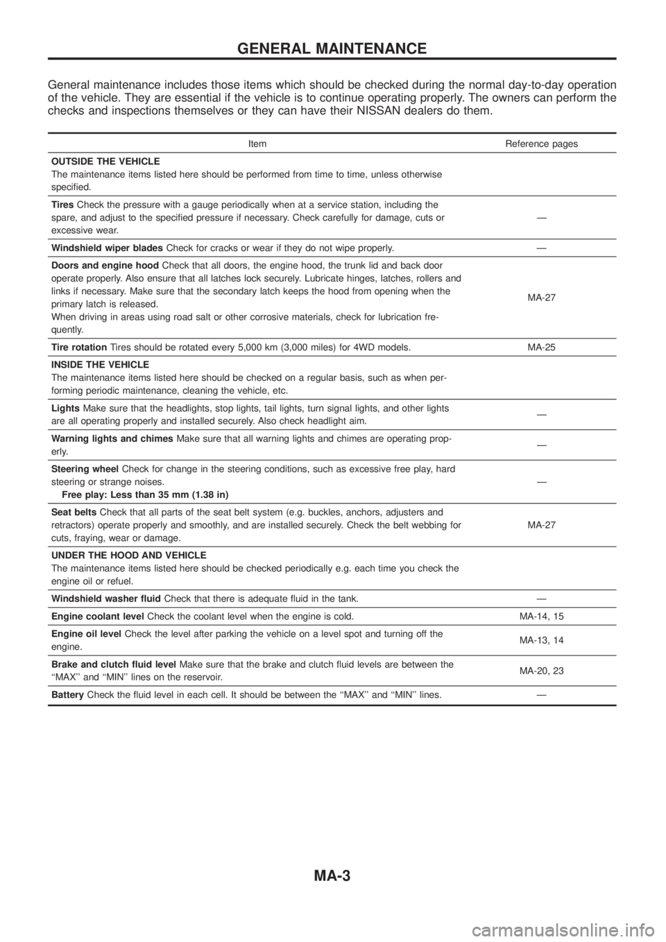
General maintenance includes those items which should be checked during the normal day-to-day operation
of the vehicle. They are essential if the vehicle is to continue operating properly. The owners can perform the
checks and inspections themselves or they can have their NISSAN dealers do them.
Item Reference pages
OUTSIDE THE VEHICLE
The maintenance items listed here should be performed from time to time, unless otherwise
speci®ed.
TiresCheck the pressure with a gauge periodically when at a service station, including the
spare, and adjust to the speci®ed pressure if necessary. Check carefully for damage, cuts or
excessive wear.Ð
Windshield wiper bladesCheck for cracks or wear if they do not wipe properly. Ð
Doors and engine hoodCheck that all doors, the engine hood, the trunk lid and back door
operate properly. Also ensure that all latches lock securely. Lubricate hinges, latches, rollers and
links if necessary. Make sure that the secondary latch keeps the hood from opening when the
primary latch is released.
When driving in areas using road salt or other corrosive materials, check for lubrication fre-
quently.MA-27
Tire rotationTires should be rotated every 5,000 km (3,000 miles) for 4WD models. MA-25
INSIDE THE VEHICLE
The maintenance items listed here should be checked on a regular basis, such as when per-
forming periodic maintenance, cleaning the vehicle, etc.
LightsMake sure that the headlights, stop lights, tail lights, turn signal lights, and other lights
are all operating properly and installed securely. Also check headlight aim.Ð
Warning lights and chimesMake sure that all warning lights and chimes are operating prop-
erly.Ð
Steering wheelCheck for change in the steering conditions, such as excessive free play, hard
steering or strange noises.
Free play: Less than 35 mm (1.38 in)Ð
Seat beltsCheck that all parts of the seat belt system (e.g. buckles, anchors, adjusters and
retractors) operate properly and smoothly, and are installed securely. Check the belt webbing for
cuts, fraying, wear or damage.MA-27
UNDER THE HOOD AND VEHICLE
The maintenance items listed here should be checked periodically e.g. each time you check the
engine oil or refuel.
Windshield washer ¯uidCheck that there is adequate ¯uid in the tank. Ð
Engine coolant levelCheck the coolant level when the engine is cold. MA-14, 15
Engine oil levelCheck the level after parking the vehicle on a level spot and turning off the
engine.MA-13, 14
Brake and clutch ¯uid levelMake sure that the brake and clutch ¯uid levels are between the
``MAX'' and ``MIN'' lines on the reservoir.MA-20, 23
BatteryCheck the ¯uid level in each cell. It should be between the ``MAX'' and ``MIN'' lines. Ð
GENERAL MAINTENANCE
MA-3
Page 1175 of 1226
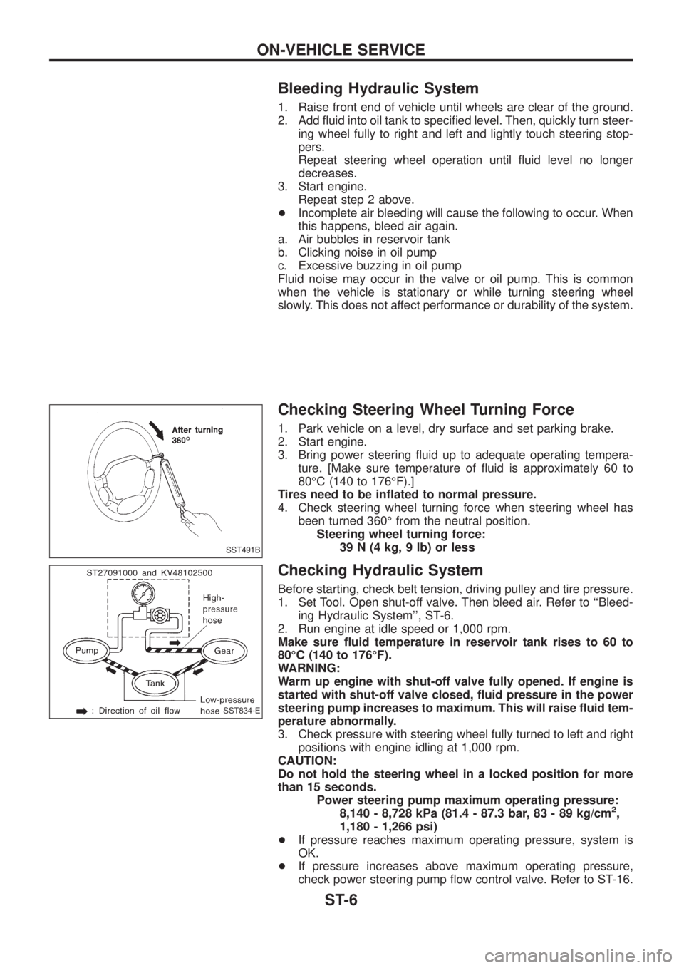
Bleeding Hydraulic System
1. Raise front end of vehicle until wheels are clear of the ground.
2. Add ¯uid into oil tank to speci®ed level. Then, quickly turn steer-
ing wheel fully to right and left and lightly touch steering stop-
pers.
Repeat steering wheel operation until ¯uid level no longer
decreases.
3. Start engine.
Repeat step 2 above.
+Incomplete air bleeding will cause the following to occur. When
this happens, bleed air again.
a. Air bubbles in reservoir tank
b. Clicking noise in oil pump
c. Excessive buzzing in oil pump
Fluid noise may occur in the valve or oil pump. This is common
when the vehicle is stationary or while turning steering wheel
slowly. This does not affect performance or durability of the system.
Checking Steering Wheel Turning Force
1. Park vehicle on a level, dry surface and set parking brake.
2. Start engine.
3. Bring power steering ¯uid up to adequate operating tempera-
ture. [Make sure temperature of ¯uid is approximately 60 to
80ÉC (140 to 176ÉF).]
Tires need to be in¯ated to normal pressure.
4. Check steering wheel turning force when steering wheel has
been turned 360É from the neutral position.
Steering wheel turning force:
39 N (4 kg, 9 lb) or less
Checking Hydraulic System
Before starting, check belt tension, driving pulley and tire pressure.
1. Set Tool. Open shut-off valve. Then bleed air. Refer to ``Bleed-
ing Hydraulic System'', ST-6.
2. Run engine at idle speed or 1,000 rpm.
Make sure ¯uid temperature in reservoir tank rises to 60 to
80ÉC (140 to 176ÉF).
WARNING:
Warm up engine with shut-off valve fully opened. If engine is
started with shut-off valve closed, ¯uid pressure in the power
steering pump increases to maximum. This will raise ¯uid tem-
perature abnormally.
3. Check pressure with steering wheel fully turned to left and right
positions with engine idling at 1,000 rpm.
CAUTION:
Do not hold the steering wheel in a locked position for more
than 15 seconds.
Power steering pump maximum operating pressure:
8,140 - 8,728 kPa (81.4 - 87.3 bar, 83 - 89 kg/cm
2,
1,180 - 1,266 psi)
+If pressure reaches maximum operating pressure, system is
OK.
+If pressure increases above maximum operating pressure,
check power steering pump ¯ow control valve. Refer to ST-16.
SST491B
SST834-E
ON-VEHICLE SERVICE
ST-6