Page 175 of 1226
4. Clean spray hole of nozzle body by using Tool.
To prevent spray hole from canting, always clean it by start-
ing with inner side and working towards outside.
5. Decarbonate nozzle needle tip by using Tool.
6. Check needle sinking.
(1) Pull needle about halfway out from body and then release it.
(2) Needle should sink into body very smoothly from just its own
weight.
(3) Repeat this test and rotate needle slightly each time.
If needle fails to sink smoothly from any position, replace both
needle and body as a unit.
Assembly (No.2-4nozzles)
Assemble in the reverse order of disassembly, observing the fol-
lowing.
If nozzle body is not installed properly, Tool cannot be
removed and nozzle body may be damaged.
Holder to nozzle nut:
: 78-98Nzm (8.0 - 10.0 kg-m, 58 - 72 ft-lb)
SEF833
SEF834
SEF835
SEF671A
INJECTION NOZZLE
Cleaning (No.2-4nozzles) (Cont'd)
EC-24
Page 194 of 1226

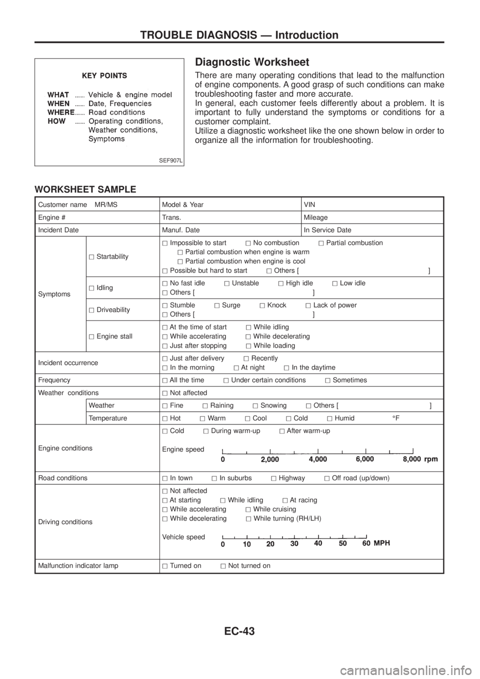
Diagnostic Worksheet
There are many operating conditions that lead to the malfunction
of engine components. A good grasp of such conditions can make
troubleshooting faster and more accurate.
In general, each customer feels differently about a problem. It is
important to fully understand the symptoms or conditions for a
customer complaint.
Utilize a diagnostic worksheet like the one shown below in order to
organize all the information for troubleshooting.
WORKSHEET SAMPLE
Customer name MR/MS Model & Year VIN
Engine # Trans. Mileage
Incident Date Manuf. Date In Service Date
SymptomshStartabilityhImpossible to starthNo combustionhPartial combustion
hPartial combustion when engine is warm
hPartial combustion when engine is cool
hPossible but hard to starthOthers [ ]
hIdlinghNo fast idlehUnstablehHigh idlehLow idle
hOthers [ ]
hDriveabilityhStumblehSurgehKnockhLack of power
hOthers [ ]
hEngine stallhAt the time of starthWhile idling
hWhile acceleratinghWhile decelerating
hJust after stoppinghWhile loading
Incident occurrencehJust after deliveryhRecently
hIn the morninghAt nighthIn the daytime
FrequencyhAll the timehUnder certain conditionshSometimes
Weather conditionshNot affected
WeatherhFinehRaininghSnowinghOthers [ ]
TemperaturehHothWarmhCoolhColdhHumid ÉF
Engine conditionshColdhDuring warm-uphAfter warm-up
Engine speed
Road conditionshIn townhIn suburbshHighwayhOff road (up/down)
Driving conditionshNot affected
hAt startinghWhile idlinghAt racing
hWhile acceleratinghWhile cruising
hWhile deceleratinghWhile turning (RH/LH)
Vehicle speed
Malfunction indicator lamphTurned onhNot turned on
SEF907L
TROUBLE DIAGNOSIS Ð Introduction
EC-43
Page 198 of 1226

jA
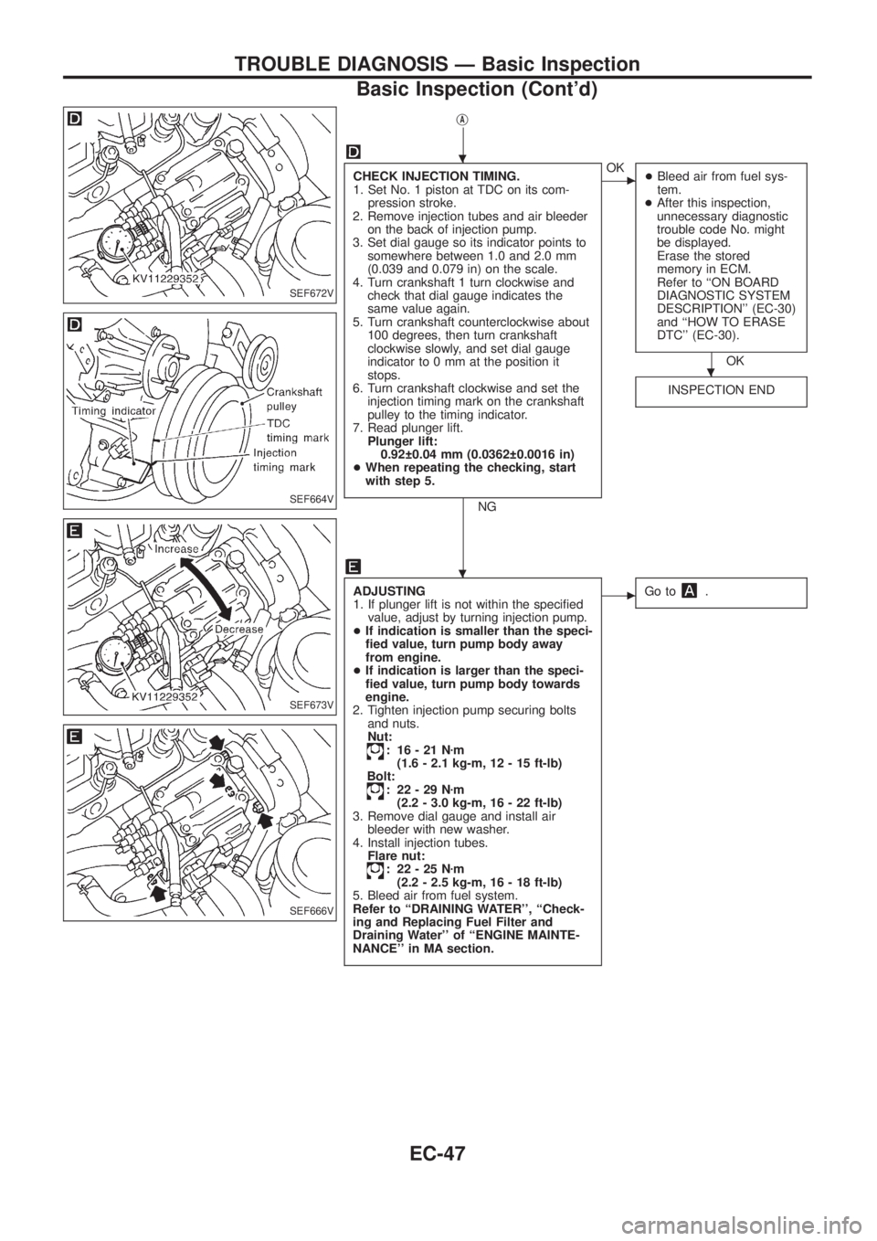
CHECK INJECTION TIMING.
1. Set No. 1 piston at TDC on its com-
pression stroke.
2. Remove injection tubes and air bleeder
on the back of injection pump.
3. Set dial gauge so its indicator points to
somewhere between 1.0 and 2.0 mm
(0.039 and 0.079 in) on the scale.
4. Turn crankshaft 1 turn clockwise and
check that dial gauge indicates the
same value again.
5. Turn crankshaft counterclockwise about
100 degrees, then turn crankshaft
clockwise slowly, and set dial gauge
indicator to 0 mm at the position it
stops.
6. Turn crankshaft clockwise and set the
injection timing mark on the crankshaft
pulley to the timing indicator.
7. Read plunger lift.
Plunger lift:
0.92 0.04 mm (0.0362 0.0016 in)
+When repeating the checking, start
with step 5.
NG
cOK
+Bleed air from fuel sys-
tem.
+After this inspection,
unnecessary diagnostic
trouble code No. might
be displayed.
Erase the stored
memory in ECM.
Refer to ``ON BOARD
DIAGNOSTIC SYSTEM
DESCRIPTION'' (EC-30)
and ``HOW TO ERASE
DTC'' (EC-30).
OK
INSPECTION END
ADJUSTING
1. If plunger lift is not within the speci®ed
value, adjust by turning injection pump.
+If indication is smaller than the speci-
®ed value, turn pump body away
from engine.
+If indication is larger than the speci-
®ed value, turn pump body towards
engine.
2. Tighten injection pump securing bolts
and nuts.
Nut:
: 16-21Nzm
(1.6 - 2.1 kg-m, 12 - 15 ft-lb)
Bolt:
: 22-29Nzm
(2.2 - 3.0 kg-m, 16 - 22 ft-lb)
3. Remove dial gauge and install air
bleeder with new washer.
4. Install injection tubes.
Flare nut:
: 22-25Nzm
(2.2 - 2.5 kg-m, 16 - 18 ft-lb)
5. Bleed air from fuel system.
Refer to ``DRAINING WATER'', ``Check-
ing and Replacing Fuel Filter and
Draining Water'' of ``ENGINE MAINTE-
NANCE'' in MA section.
cGo to.
SEF672V
SEF664V
SEF673V
SEF666V
.
.
.
TROUBLE DIAGNOSIS Ð Basic Inspection
Basic Inspection (Cont'd)
EC-47
Page 529 of 1226
INSTALLATION
1. Lower antenna rod by operating antenna motor.
2. Insert gear section of antenna rope into place with it facing
toward antenna motor.
3. As soon as antenna rope is wound on antenna motor, stop
antenna motor. Insert antenna rod lower end into antenna
motor pipe.
4. Retract antenna rod completely by operating antenna motor.
5. Install antenna nut and base.
Window Antenna Repair
ELEMENT CHECK
1. Attach probe circuit tester (in ohm range) to antenna terminal
on each side.
2. If an element is broken, no continuity will exist.
CEL747
SEL250I
SEL252I
AUDIO ANTENNA
Antenna Rod Replacement (Cont'd)
EL-184
Page 683 of 1226
3. Remove engine gussets and oil pan bolts.
+Remove bolts/nuts in numerical order shown in ®gure, alternat-
ing left and right ones toward the center.
4. Remove oil pump assembly.
Installation
Always install with new oil seal.
1. Install oil pump assembly.
Location Bolt length mm (in)
V120 (0.79)
V235 (1.38)
V345 (1.77)
V455 (2.17)
2. Install oil pan. Tighten bolts in the order shown in the ®gure.
+Always replace oil pan gaskets with new ones when reas-
sembling.
+Install oil pan gasket after cleaning the contacting surface.
+Oil pan bolts/nuts:
Bolt
:8-12Nzm (0.8 - 1.2 kg-m, 69 - 104 in-lb)
Nut
:10-14Nzm (1.0 - 1.4 kg-m, 87 - 122 in-lb)
3. Install engine gusset and oil pan guard.
SEM739B
SEM432C
SEM794F
SEM739BA
OIL PAN
Removal (Cont'd)
EM-15
Page 687 of 1226
Installation
1. Con®rm that No. 1 cylinder is set at BDC on its expansion
stroke as follows:
Con®rm that crankshaft key is at the bottom.
2. Set timing belt.
a. Ensure timing belt, sprockets and pulleys are clean and
free from oil or water. Do not bend or twist timing belt too
much.
b. Align white lines on timing belt with matching mark on
camshaft sprocket, crankshaft sprocket and injection
pump pulley.
c. Point arrow on timing belt toward front.
SMA771B
TIMING BELT
EM-19
Page 689 of 1226

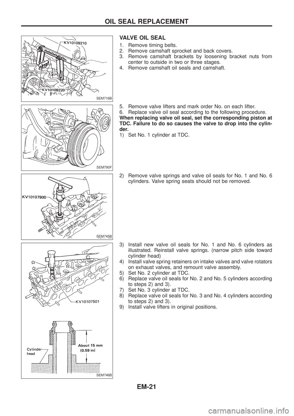
VALVE OIL SEAL
1. Remove timing belts.
2. Remove camshaft sprocket and back covers.
3. Remove camshaft brackets by loosening bracket nuts from
center to outside in two or three stages.
4. Remove camshaft oil seals and camshaft.
5. Remove valve lifters and mark order No. on each lifter.
6. Replace valve oil seal according to the following procedure.
When replacing valve oil seal, set the corresponding piston at
TDC. Failure to do so causes the valve to drop into the cylin-
der.
1) Set No. 1 cylinder at TDC.
2) Remove valve springs and valve oil seals for No. 1 and No. 6
cylinders. Valve spring seats should not be removed.
3) Install new valve oil seals for No. 1 and No. 6 cylinders as
illustrated. Reinstall valve springs. (narrow pitch side toward
cylinder head)
4) Install valve spring retainers on intake valves and valve rotators
on exhaust valves, and remount valve assembly.
5) Set No. 2 cylinder at TDC.
6) Replace valve oil seals for No. 2 and No. 5 cylinders according
to steps 2) and 3).
7) Set No. 3 cylinder at TDC.
8) Replace valve oil seals for No. 3 and No. 4 cylinders according
to steps 2) and 3).
9) Install valve lifters in original positions.
SEM716B
SEM790F
SEM745B
SEM746B
OIL SEAL REPLACEMENT
EM-21
Page 706 of 1226

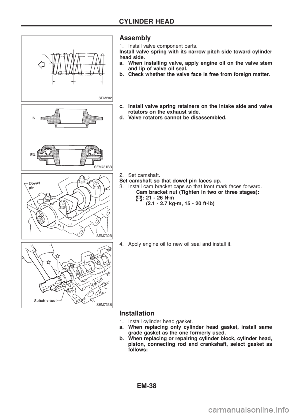
Assembly
1. Install valve component parts.
Install valve spring with its narrow pitch side toward cylinder
head side.
a. When installing valve, apply engine oil on the valve stem
and lip of valve oil seal.
b. Check whether the valve face is free from foreign matter.
c. Install valve spring retainers on the intake side and valve
rotators on the exhaust side.
d. Valve rotators cannot be disassembled.
2. Set camshaft.
Set camshaft so that dowel pin faces up.
3. Install cam bracket caps so that front mark faces forward.
Cam bracket nut (Tighten in two or three stages):
:21-26Nzm
(2.1 - 2.7 kg-m, 15 - 20 ft-lb)
4. Apply engine oil to new oil seal and install it.
Installation
1. Install cylinder head gasket.
a. When replacing only cylinder head gasket, install same
grade gasket as the one formerly used.
b. When replacing or repairing cylinder block, cylinder head,
piston, connecting rod and crankshaft, select gasket as
follows:
SEM202
SEM731BB
SEM732B
SEM733B
CYLINDER HEAD
EM-38