2006 NISSAN PATROL water pump
[x] Cancel search: water pumpPage 19 of 1226

Brake Booster
ON-VEHICLE SERVICE
Operating check
+Depress brake pedal several times with engine off. After
exhausting vacuum, make sure there is no change in pedal
stroke.
+ Depress brake pedal, then start engine. If pedal goes down
slightly, operation is normal.
Airtight check
+Start engine, and stop it after one or two minutes. Depress
brake pedal several times slowly. Booster is airtight if pedal
stroke is less each time.
+ Depress brake pedal while engine is running, and stop engine
with pedal depressed. The pedal stroke should not change after
holding pedal down for 30 seconds.
REMOVAL
CAUTION:
+Be careful not to splash brake ¯uid on painted areas; it
may cause paint damage. If brake ¯uid is splashed on
painted areas, wash it away with water immediately.
+ Be careful not to deform or bend brake pipes, during
removal of booster.
INSPECTION
Output rod length check
1. Apply vacuum of þ66.7 kPa (þ500 mmHg, þ19.69 inHg) to
brake booster with a hand vacuum pump.
2. Check output rod length. Speci®ed length:10.275 - 10.525 mm (0.4045 - 0.4144 in)
INSTALLATION
CAUTION:
+Be careful not to deform or bend brake pipes during instal-
lation of booster.
+ Replace clevis pin if damaged.
+ Re®ll with new brake ¯uid ``DOT 3''.
+ Never reuse drained brake ¯uid.
+ Take care not to damage brake booster mounting bolt
thread when installing. Due to the narrow angle of
installation, the threads can be damaged by the dash
panel.
SBR002A
SBR365AA
SBR170E
SBR281A
SBR116BF
BRAKE BOOSTER
BR-15
Page 197 of 1226
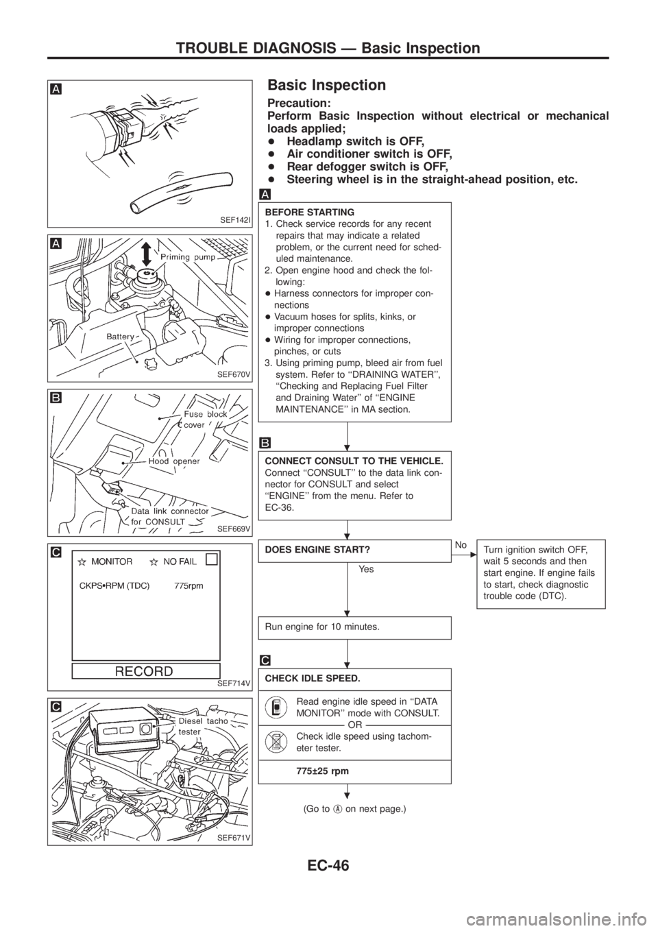
Basic Inspection
Precaution:
Perform Basic Inspection without electrical or mechanical
loads applied;
+Headlamp switch is OFF,
+Air conditioner switch is OFF,
+Rear defogger switch is OFF,
+Steering wheel is in the straight-ahead position, etc.
BEFORE STARTING
1. Check service records for any recent
repairs that may indicate a related
problem, or the current need for sched-
uled maintenance.
2. Open engine hood and check the fol-
lowing:
+Harness connectors for improper con-
nections
+Vacuum hoses for splits, kinks, or
improper connections
+Wiring for improper connections,
pinches, or cuts
3. Using priming pump, bleed air from fuel
system. Refer to ``DRAINING WATER'',
``Checking and Replacing Fuel Filter
and Draining Water'' of ``ENGINE
MAINTENANCE'' in MA section.
CONNECT CONSULT TO THE VEHICLE.
Connect ``CONSULT'' to the data link con-
nector for CONSULT and select
``ENGINE'' from the menu. Refer to
EC-36.
DOES ENGINE START?
Ye s
cNo
Turn ignition switch OFF,
wait 5 seconds and then
start engine. If engine fails
to start, check diagnostic
trouble code (DTC).
Run engine for 10 minutes.
CHECK IDLE SPEED.
----------------------------------------------------------------------------------------------------------------------------------------------------------------------------------------------------------------------------------------------------------------------------------------------------------------
Read engine idle speed in ``DATA
MONITOR'' mode with CONSULT.
--------------------------------------------------------------------------------------------------------------------------------------OR--------------------------------------------------------------------------------------------------------------------------------------
Check idle speed using tachom-
eter tester.
----------------------------------------------------------------------------------------------------------------------------------------------------------------------------------------------------------------------------------------------------------------------------------------------------------------
775 25 rpm
(Go tojAon next page.)
SEF142I
SEF670V
SEF669V
SEF714V
SEF671V
.
.
.
.
.
TROUBLE DIAGNOSIS Ð Basic Inspection
EC-46
Page 198 of 1226
jA
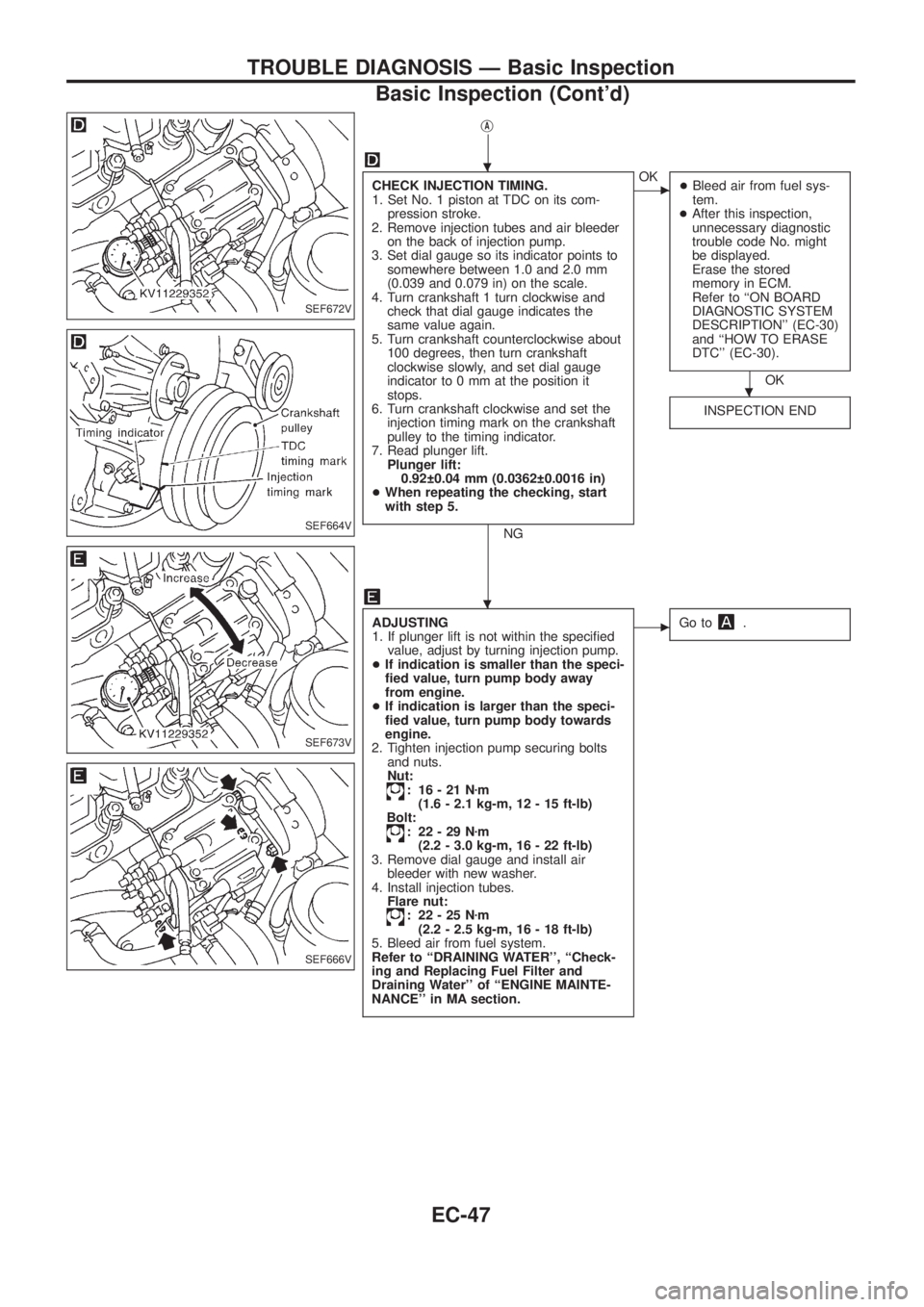
CHECK INJECTION TIMING.
1. Set No. 1 piston at TDC on its com-
pression stroke.
2. Remove injection tubes and air bleeder
on the back of injection pump.
3. Set dial gauge so its indicator points to
somewhere between 1.0 and 2.0 mm
(0.039 and 0.079 in) on the scale.
4. Turn crankshaft 1 turn clockwise and
check that dial gauge indicates the
same value again.
5. Turn crankshaft counterclockwise about
100 degrees, then turn crankshaft
clockwise slowly, and set dial gauge
indicator to 0 mm at the position it
stops.
6. Turn crankshaft clockwise and set the
injection timing mark on the crankshaft
pulley to the timing indicator.
7. Read plunger lift.
Plunger lift:
0.92 0.04 mm (0.0362 0.0016 in)
+When repeating the checking, start
with step 5.
NG
cOK
+Bleed air from fuel sys-
tem.
+After this inspection,
unnecessary diagnostic
trouble code No. might
be displayed.
Erase the stored
memory in ECM.
Refer to ``ON BOARD
DIAGNOSTIC SYSTEM
DESCRIPTION'' (EC-30)
and ``HOW TO ERASE
DTC'' (EC-30).
OK
INSPECTION END
ADJUSTING
1. If plunger lift is not within the speci®ed
value, adjust by turning injection pump.
+If indication is smaller than the speci-
®ed value, turn pump body away
from engine.
+If indication is larger than the speci-
®ed value, turn pump body towards
engine.
2. Tighten injection pump securing bolts
and nuts.
Nut:
: 16-21Nzm
(1.6 - 2.1 kg-m, 12 - 15 ft-lb)
Bolt:
: 22-29Nzm
(2.2 - 3.0 kg-m, 16 - 22 ft-lb)
3. Remove dial gauge and install air
bleeder with new washer.
4. Install injection tubes.
Flare nut:
: 22-25Nzm
(2.2 - 2.5 kg-m, 16 - 18 ft-lb)
5. Bleed air from fuel system.
Refer to ``DRAINING WATER'', ``Check-
ing and Replacing Fuel Filter and
Draining Water'' of ``ENGINE MAINTE-
NANCE'' in MA section.
cGo to.
SEF672V
SEF664V
SEF673V
SEF666V
.
.
.
TROUBLE DIAGNOSIS Ð Basic Inspection
Basic Inspection (Cont'd)
EC-47
Page 265 of 1226

TER-
MINAL
NO.WIRE
COLORITEM CONDITIONDATA
(DC Voltage and Pulse
Signal)
15 Y/L Air conditioner relayEngine is running.
Air conditioner switch is ``OFF''.BATTERY VOLTAGE
(11 - 14V)
Engine is running.
Both air conditioner switch and blower fan
switch are ``ON''.
(Compressor is operating.)0-1V
ON BOARD DIAGNOSIS LOGIC
This diagnosis continuously monitors the engine coolant temperature.
If the cooling fan or another component in the cooling system malfunctions, engine coolant temperature will
rise.
When the engine coolant temperature reaches an abnormally high temperature condition, a malfunction is
indicated.
Diagnostic Trouble
Code No.Malfunction is detected when ...Check Items
(Possible Cause)
28+Cooling fan does not operate properly (Overheat).
+Cooling fan system does not operate properly (Over-
heat).
+Engine coolant was not added to the system using
the proper ®lling method.+Harness or connectors
(The cooling fan circuit is open or shorted.)
+Cooling fan
+Radiator hose
+Radiator
+Radiator cap
+Water pump
+Thermostat
+Fan belt
+Engine coolant temperature sensor
For more information, refer to ``MAIN 12
CAUSES OF OVERHEATING'', EC-120.
CAUTION:
When a malfunction is indicated, be sure to replace the coolant following the procedure in the MA
section (``Changing Engine Coolant'', ``ENGINE MAINTENANCE''). Also, replace the engine oil.
a. Fill radiator with coolant up to speci®ed level with a ®lling speed of 2 liters per minute. Be sure to
use coolant with the proper mixture ratio. Refer to MA section (``Anti-freeze Coolant Mixture Ratio'',
``RECOMMENDED FLUIDS AND LUBRICANTS'').
b. After re®lling coolant, run engine to ensure that no water-¯ow noise is emitted.
TROUBLE DIAGNOSIS FOR ``OVER HEAT'' (DTC 28)
Cooling Fan (Overheat) (Cont'd)
EC-114
Page 270 of 1226
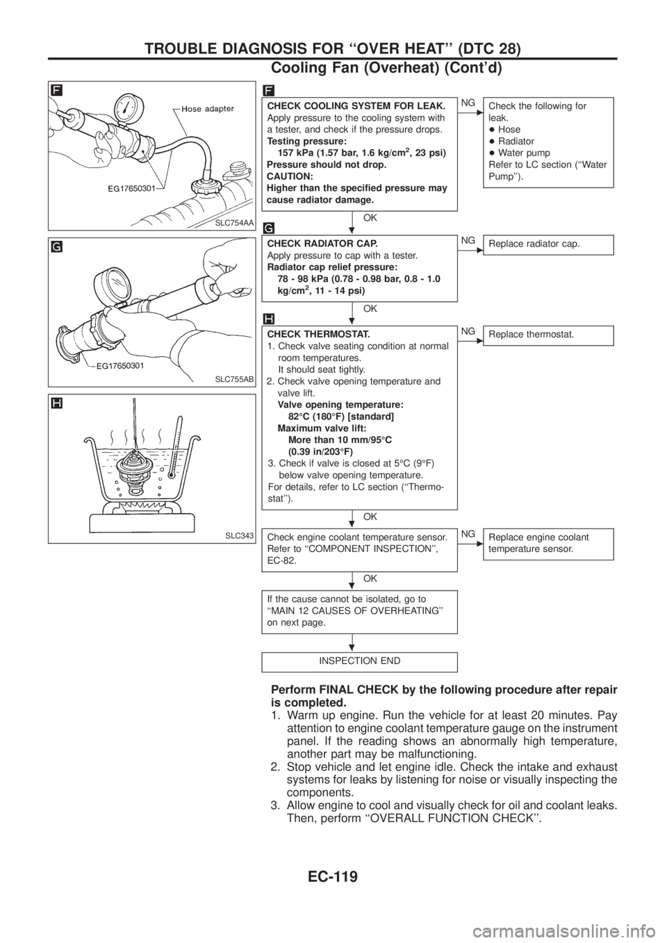
CHECK COOLING SYSTEM FOR LEAK.
Apply pressure to the cooling system with
a tester, and check if the pressure drops.
Testing pressure:
157 kPa (1.57 bar, 1.6 kg/cm
2, 23 psi)
Pressure should not drop.
CAUTION:
Higher than the speci®ed pressure may
cause radiator damage.
OK
cNG
Check the following for
leak.
+Hose
+Radiator
+Water pump
Refer to LC section (``Water
Pump'').
CHECK RADIATOR CAP.
Apply pressure to cap with a tester.
Radiator cap relief pressure:
78 - 98 kPa (0.78 - 0.98 bar, 0.8 - 1.0
kg/cm
2, 11 - 14 psi)
OK
cNG
Replace radiator cap.
CHECK THERMOSTAT.
1. Check valve seating condition at normal
room temperatures.
It should seat tightly.
2. Check valve opening temperature and
valve lift.
Valve opening temperature:
82ÉC (180ÉF) [standard]
Maximum valve lift:
More than 10 mm/95ÉC
(0.39 in/203ÉF)
3. Check if valve is closed at 5ÉC (9ÉF)
below valve opening temperature.
For details, refer to LC section (``Thermo-
stat'').
OK
cNG
Replace thermostat.
Check engine coolant temperature sensor.
Refer to ``COMPONENT INSPECTION'',
EC-82.
OK
cNG
Replace engine coolant
temperature sensor.
If the cause cannot be isolated, go to
``MAIN 12 CAUSES OF OVERHEATING''
on next page.
INSPECTION END
Perform FINAL CHECK by the following procedure after repair
is completed.
1. Warm up engine. Run the vehicle for at least 20 minutes. Pay
attention to engine coolant temperature gauge on the instrument
panel. If the reading shows an abnormally high temperature,
another part may be malfunctioning.
2. Stop vehicle and let engine idle. Check the intake and exhaust
systems for leaks by listening for noise or visually inspecting the
components.
3. Allow engine to cool and visually check for oil and coolant leaks.
Then, perform ``OVERALL FUNCTION CHECK''.
SLC754AA
SLC755AB
SLC343
.
.
.
.
.
TROUBLE DIAGNOSIS FOR ``OVER HEAT'' (DTC 28)
Cooling Fan (Overheat) (Cont'd)
EC-119
Page 676 of 1226
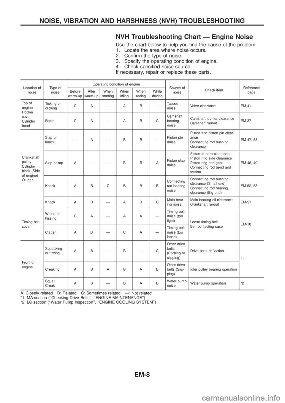
NVH Troubleshooting Chart Ð Engine Noise
Use the chart below to help you ®nd the cause of the problem.
1. Locate the area where noise occurs.
2. Con®rm the type of noise.
3. Specify the operating condition of engine.
4. Check speci®ed noise source.
If necessary, repair or replace these parts.
Location of
noiseType of
noiseOperating condition of engine
Source of
noiseCheck itemReference
page Before
warm-upAfter
warm-upWhen
startingWhen
idlingWhen
racingWhile
driving
To p o f
engine
Rocker
cover
Cylinder
headTicking or
clickingCAÐABÐTappet
noiseValve clearance EM-41
Rattle C A Ð A B CCamshaft
bearing
noiseCamshaft journal clearance
Camshaft runoutEM-37
Crankshaft
pulley
Cylinder
block (Side
of engine)
Oil panSlap or
knockÐAÐB BÐPiston pin
noisePiston and piston pin clear-
ance
Connecting rod bushing
clearanceEM-47, 53
Slap or rap A Ð Ð B B APiston slap
noisePiston-to-bore clearance
Piston ring side clearance
Piston ring end gap
Connecting rod bend and
torsionEM-48, 49
Knock A B C B B BConnecting
rod bearing
noiseConnecting rod bushing
clearance (Small end)
Connecting rod bearing
clearance (Big end)EM-52, 53
Knock A B Ð A B CMain bear-
ing noiseMain bearing oil clearance
Crankshaft runoutEM-51
Timing belt
coverWhine or
hissingCAÐAAÐTiming belt
noise (too
tight)
Loose timing belt
Belt contacting caseEM-18
Clatter A B Ð C A ÐTiming belt
noise (too
loose)
Front of
engineSqueaking
or ®zzingABÐBÐCOther drive
belts
(Sticking or
slipping)Drive belts de¯ection
*1
CreakingABABABOther drive
belts (Slip-
ping)Idler pulley bearing operation
Squall
CreakABÐBABWater pump
noiseWater pump operation *2
A: Closely related B: Related C: Sometimes related Ð: Not related
*1: MA section (``Checking Drive Belts'', ``ENGINE MAINTENANCE'')
*2: LC section (``Water Pump Inspection'', ``ENGINE COOLING SYSTEM'')
NOISE, VIBRATION AND HARSHNESS (NVH) TROUBLESHOOTING
EM-8
Page 684 of 1226
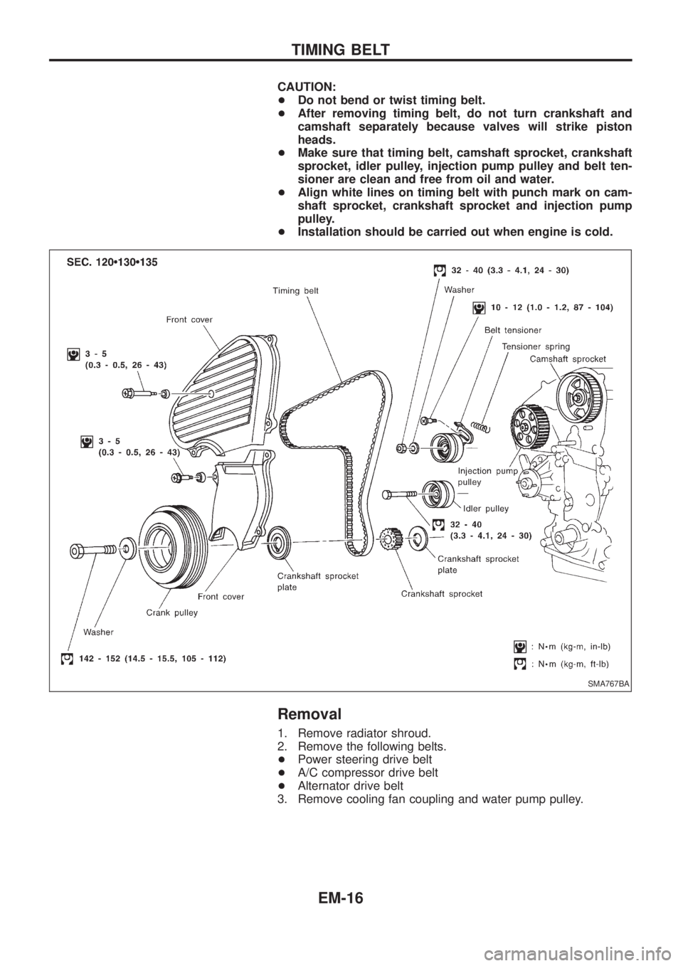
CAUTION:
+Do not bend or twist timing belt.
+After removing timing belt, do not turn crankshaft and
camshaft separately because valves will strike piston
heads.
+Make sure that timing belt, camshaft sprocket, crankshaft
sprocket, idler pulley, injection pump pulley and belt ten-
sioner are clean and free from oil and water.
+Align white lines on timing belt with punch mark on cam-
shaft sprocket, crankshaft sprocket and injection pump
pulley.
+Installation should be carried out when engine is cold.
Removal
1. Remove radiator shroud.
2. Remove the following belts.
+Power steering drive belt
+A/C compressor drive belt
+Alternator drive belt
3. Remove cooling fan coupling and water pump pulley.
SMA767BA
TIMING BELT
EM-16
Page 686 of 1226
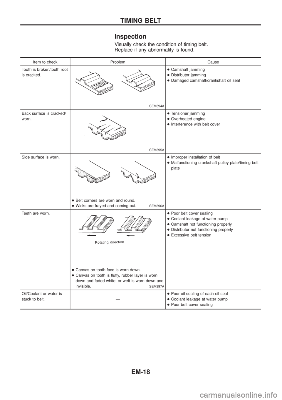
Inspection
Visually check the condition of timing belt.
Replace if any abnormality is found.
Item to check Problem Cause
Tooth is broken/tooth root
is cracked.
SEM394A
+Camshaft jamming
+Distributor jamming
+Damaged camshaft/crankshaft oil seal
Back surface is cracked/
worn.
SEM395A
+Tensioner jamming
+Overheated engine
+Interference with belt cover
Side surface is worn.
+Belt corners are worn and round.
+Wicks are frayed and coming out.
SEM396A
+Improper installation of belt
+Malfunctioning crankshaft pulley plate/timing belt
plate
Teeth are worn.
+Canvas on tooth face is worn down.
+Canvas on tooth is ¯uffy, rubber layer is worn
down and faded white, or weft is worn down and
invisible.
SEM397A
+Poor belt cover sealing
+Coolant leakage at water pump
+Camshaft not functioning properly
+Distributor not functioning properly
+Excessive belt tension
Oil/Coolant or water is
stuck to belt. Ð+Poor oil sealing of each oil seal
+Coolant leakage at water pump
+Poor belt cover sealing
TIMING BELT
EM-18