2006 NISSAN PATROL Break
[x] Cancel search: BreakPage 157 of 1226
Precautions
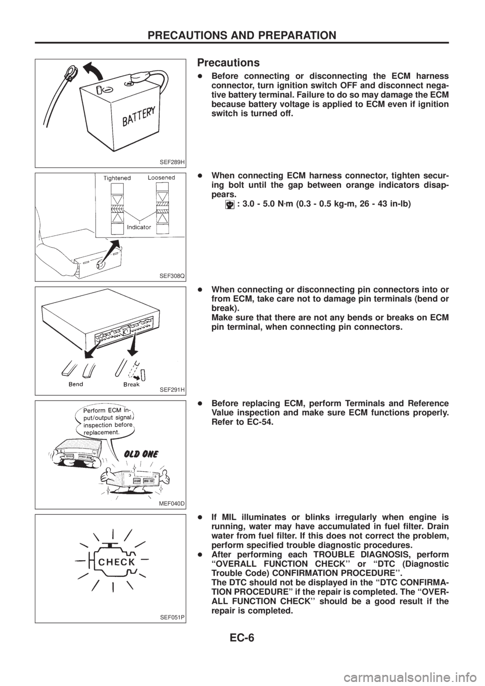
+Before connecting or disconnecting the ECM harness
connector, turn ignition switch OFF and disconnect nega-
tive battery terminal. Failure to do so may damage the ECM
because battery voltage is applied to ECM even if ignition
switch is turned off.
+When connecting ECM harness connector, tighten secur-
ing bolt until the gap between orange indicators disap-
pears.
: 3.0 - 5.0 Nzm (0.3 - 0.5 kg-m, 26 - 43 in-lb)
+When connecting or disconnecting pin connectors into or
from ECM, take care not to damage pin terminals (bend or
break).
Make sure that there are not any bends or breaks on ECM
pin terminal, when connecting pin connectors.
+Before replacing ECM, perform Terminals and Reference
Value inspection and make sure ECM functions properly.
Refer to EC-54.
+If MIL illuminates or blinks irregularly when engine is
running, water may have accumulated in fuel ®lter. Drain
water from fuel ®lter. If this does not correct the problem,
perform speci®ed trouble diagnostic procedures.
+After performing each TROUBLE DIAGNOSIS, perform
``OVERALL FUNCTION CHECK'' or ``DTC (Diagnostic
Trouble Code) CONFIRMATION PROCEDURE''.
The DTC should not be displayed in the ``DTC CONFIRMA-
TION PROCEDUREº if the repair is completed. The ``OVER-
ALL FUNCTION CHECK'' should be a good result if the
repair is completed.
SEF289H
SEF308Q
SEF291H
MEF040D
SEF051P
PRECAUTIONS AND PREPARATION
EC-6
Page 342 of 1226

ELECTRICAL SYSTEM
SECTION
EL
When you read wiring diagrams:
+Read GI section, ``HOW TO READ WIRING DIAGRAMS''.
When you perform trouble diagnoses, read GI section, ``HOW TO FOLLOW FLOW
CHART IN TROUBLE DIAGNOSES'' and ``HOW TO PERFORM EFFICIENT DIAGNOSIS
FOR AN ELECTRICAL INCIDENT''.
+Check for any service bulletins before servicing the vehicle.
CONTENTS
PRECAUTIONS...............................................................1
Supplemental Restraint System (SRS) ``AIR
BAG'' and ``SEAT BELT PRE-TENSIONER''...............1
HARNESS CONNECTOR................................................2
Description ...................................................................2
STANDARDIZED RELAY................................................3
Description ...................................................................3
POWER SUPPLY ROUTING...........................................5
Schematic ....................................................................5
Wiring Diagram Ð POWER Ð....................................6
Fuse ...........................................................................14
Fusible Link................................................................14
Circuit Breaker Inspection .........................................14
GROUND DISTRIBUTION/LHD MODELS....................15
Engine Room Harness ..............................................15
Main Harness.............................................................19
Body Harness ............................................................22
Body No. 2 Harness ..................................................23
Back Door and Rear Window Defogger Harness .....24
Room Lamp Harness.................................................25
GROUND DISTRIBUTION/RHD MODELS...................26
Engine Room Harness ..............................................26
Main Harness.............................................................30
Body Harness ............................................................33
Body No. 2 Harness ..................................................34
Back Door and Rear Window Defogger Harness .....35
Room Lamp Harness.................................................36
BATTERY.......................................................................37
How to Handle Battery ..............................................37
Battery Test and Charging Chart ...............................40
Service Data and Speci®cations (SDS).....................44
STARTING SYSTEM.....................................................45
Wiring Diagram Ð START Ð ....................................45Trouble Diagnoses.....................................................46
Construction ...............................................................47
Removal and Installation ...........................................47
Inspection...................................................................47
Assembly ...................................................................50
Service Data and Speci®cations (SDS).....................51
CHARGING SYSTEM....................................................52
Wiring Diagram Ð CHARGE Ð ................................52
Trouble Diagnoses.....................................................53
Construction ...............................................................54
Removal and Installation ...........................................54
Disassembly...............................................................54
Inspection...................................................................55
Assembly ...................................................................56
Service Data and Speci®cations (SDS).....................56
COMBINATION SWITCH...............................................57
Check .........................................................................57
Replacement ..............................................................58
STEERING SWITCH......................................................59
Check .........................................................................59
HEADLAMP Ð Conventional Type Ð........................61
Wiring Diagram Ð H/LAMP Ð ..................................61
Trouble Diagnoses.....................................................62
Bulb Replacement .....................................................63
Aiming Adjustment .....................................................63
HEADLAMP Ð Daytime Light System Ð..................65
System Description ....................................................65
Wiring Diagram Ð DTRL Ð ......................................67
Trouble Diagnoses.....................................................69
Bulb Replacement .....................................................69
Aiming Adjustment .....................................................69
HEADLAMP Ð Headlamp Aiming Control Ð............70
System Description ....................................................70
EL
Page 348 of 1226
Description
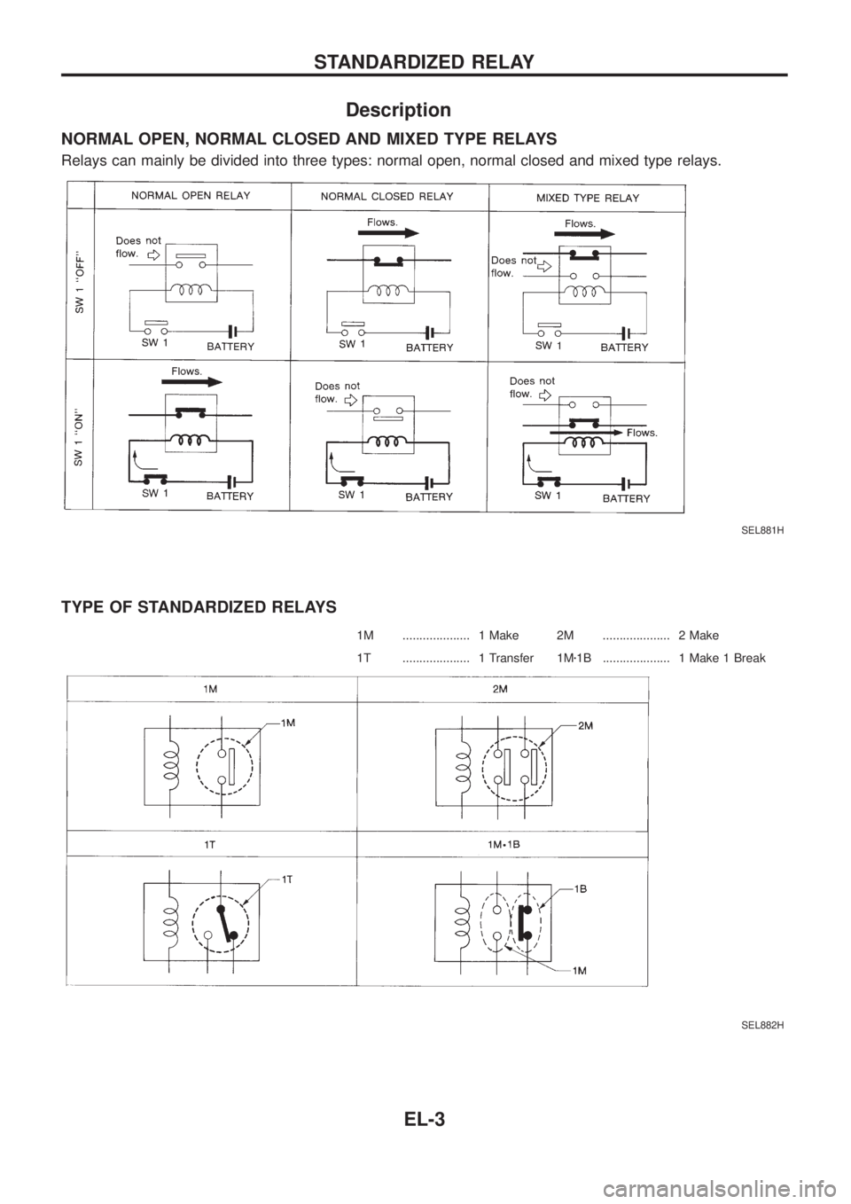
NORMAL OPEN, NORMAL CLOSED AND MIXED TYPE RELAYS
Relays can mainly be divided into three types: normal open, normal closed and mixed type relays.
TYPE OF STANDARDIZED RELAYS
1M .................... 1 Make 2M .................... 2 Make
1T .................... 1 Transfer 1Mz1B .................... 1 Make 1 Break
SEL881H
SEL882H
STANDARDIZED RELAY
EL-3
Page 359 of 1226
Fuse
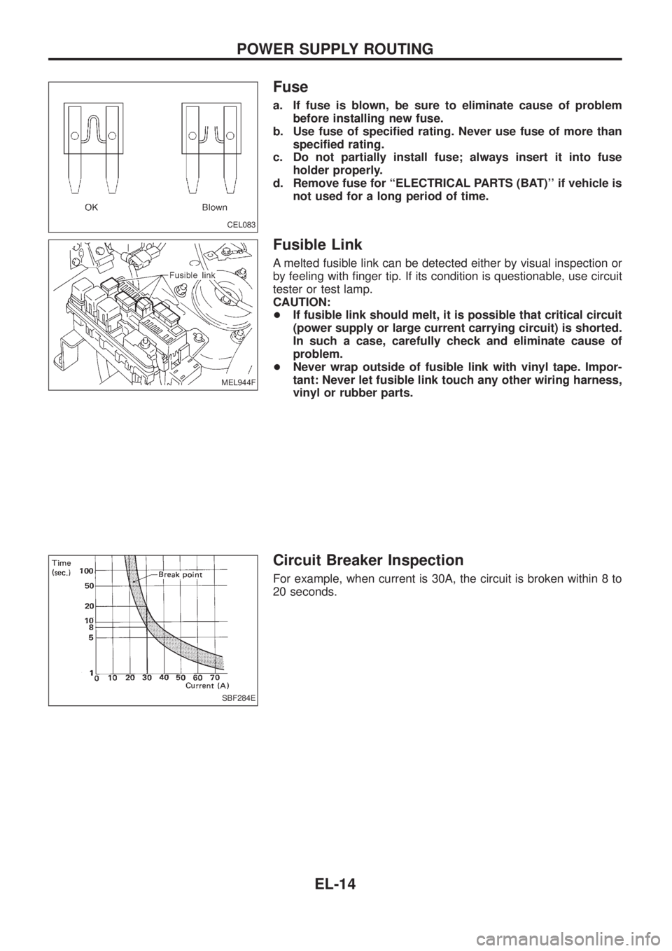
a. If fuse is blown, be sure to eliminate cause of problem
before installing new fuse.
b. Use fuse of speci®ed rating. Never use fuse of more than
speci®ed rating.
c. Do not partially install fuse; always insert it into fuse
holder properly.
d. Remove fuse for ``ELECTRICAL PARTS (BAT)'' if vehicle is
not used for a long period of time.
Fusible Link
A melted fusible link can be detected either by visual inspection or
by feeling with ®nger tip. If its condition is questionable, use circuit
tester or test lamp.
CAUTION:
+If fusible link should melt, it is possible that critical circuit
(power supply or large current carrying circuit) is shorted.
In such a case, carefully check and eliminate cause of
problem.
+Never wrap outside of fusible link with vinyl tape. Impor-
tant: Never let fusible link touch any other wiring harness,
vinyl or rubber parts.
Circuit Breaker Inspection
For example, when current is 30A, the circuit is broken within 8 to
20 seconds.
CEL083
MEL944F
SBF284E
POWER SUPPLY ROUTING
EL-14
Page 484 of 1226
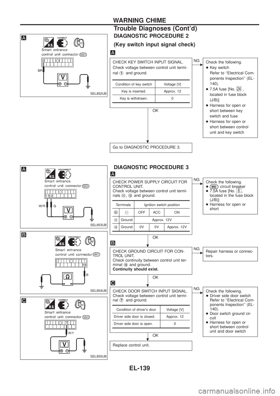
DIAGNOSTIC PROCEDURE 2
(Key switch input signal check)
CHECK KEY SWITCH INPUT SIGNAL.
Check voltage between control unit termi-
nalj
1and ground.
OK
cNG
Check the following.
+Key switch
Refer to ``Electrical Com-
ponents Inspection'' (EL-
140).
+7.5A fuse [No.
24,
located in fuse block
(J/B)]
+Harness for open or
short between key
switch and fuse
+Harness for open or
short between control
unit and key switch
Go to DIAGNOSTIC PROCEDURE 3.
Condition of key switch Voltage [V]
Key is inserted. Approx. 12
Key is withdrawn. 0
DIAGNOSTIC PROCEDURE 3
CHECK POWER SUPPLY CIRCUIT FOR
CONTROL UNIT.
Check voltage between control unit termi-
nalsj
11,j12and ground.
OK
cNG
Check the following.
+
M92circuit breaker
+7.5A fuse [No.8,
located in the fuse block
(J/B)]
+Harness for open or
short
CHECK GROUND CIRCUIT FOR CON-
TROL UNIT.
Check continuity between control unit ter-
minalj
18and ground.
Continuity should exist.
OK
cNG
Repair harness or connec-
tors.
CHECK DOOR SWITCH INPUT SIGNAL.
Check voltage between control unit termi-
nalj
7and ground.
OK
cNG
Check the following.
+Driver side door switch
Refer to ``Electrical Com-
ponents Inspection'' (EL-
140).
+Door switch ground cir-
cuit
+Harness for open or
short between control
unit and door switch
Replace control unit.
Terminals Ignition switch position
Å@OFF ACC ON
j
11Ground Approx. 12V
j
12Ground 0V 0V Approx. 12V
Condition of driver's door Voltage [V]
Driver side door is closed. Approx. 12
Driver side door is open. 0
SEL852UB
SEL853UB
SEL854UB
SEL855UB
.
.
.
.
WARNING CHIME
Trouble Diagnoses (Cont'd)
EL-139
Page 489 of 1226
Removal
1. Remove 4 bolts that secure wiper motor.
2. Detach wiper motor from wiper linkage at ball joint.
3. Remove wiper linkage.
Be careful not to break ball joint rubber boot.
Installation
+Grease ball joint portion before installation.
1. Installation is the reverse order of removal.
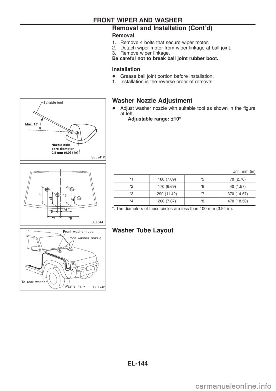
Washer Nozzle Adjustment
+Adjust washer nozzle with suitable tool as shown in the ®gure
at left.
Adjustable range: 10É
Unit: mm (in)
*1 180 (7.09) *5 70 (2.76)
*2 170 (6.69) *6 40 (1.57)
*3 290 (11.42) *7 370 (14.57)
*4 200 (7.87) *8 470 (18.50)
*: The diameters of these circles are less than 100 mm (3.94 in).
Washer Tube Layout
SEL241P
SEL544T
CEL742
FRONT WIPER AND WASHER
Removal and Installation (Cont'd)
EL-144
Page 510 of 1226
Filament Repair
REPAIR EQUIPMENT
1. Conductive silver composition (Dupont No. 4817 or equivalent)
2. Ruler 30 cm (11.8 in) long
3. Drawing pen
4. Heat gun
5. Alcohol
6. Cloth
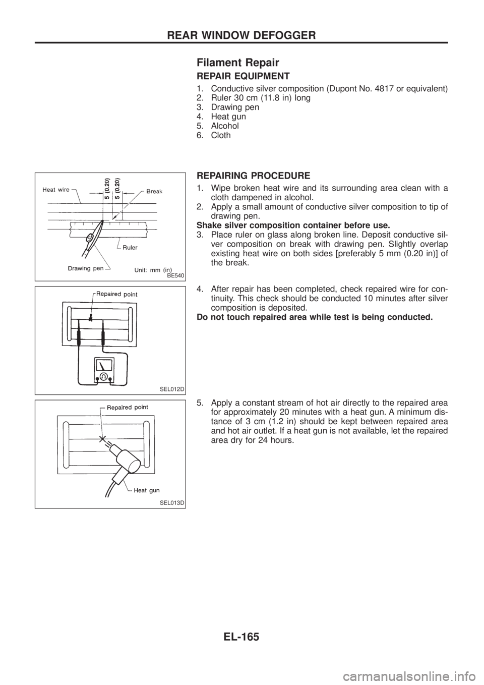
REPAIRING PROCEDURE
1. Wipe broken heat wire and its surrounding area clean with a
cloth dampened in alcohol.
2. Apply a small amount of conductive silver composition to tip of
drawing pen.
Shake silver composition container before use.
3. Place ruler on glass along broken line. Deposit conductive sil-
ver composition on break with drawing pen. Slightly overlap
existing heat wire on both sides [preferably 5 mm (0.20 in)] of
the break.
4. After repair has been completed, check repaired wire for con-
tinuity. This check should be conducted 10 minutes after silver
composition is deposited.
Do not touch repaired area while test is being conducted.
5. Apply a constant stream of hot air directly to the repaired area
for approximately 20 minutes with a heat gun. A minimum dis-
tance of 3 cm (1.2 in) should be kept between repaired area
and hot air outlet. If a heat gun is not available, let the repaired
area dry for 24 hours.
BE540
SEL012D
SEL013D
REAR WINDOW DEFOGGER
EL-165
Page 548 of 1226
Trouble Diagnoses
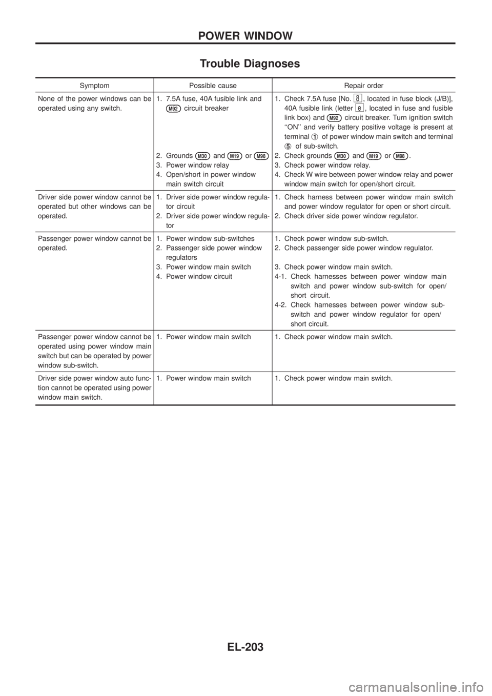
Symptom Possible cause Repair order
None of the power windows can be
operated using any switch.1. 7.5A fuse, 40A fusible link and
M92circuit breaker
2. Grounds
M30andM19orM98
3. Power window relay
4. Open/short in power window
main switch circuit1. Check 7.5A fuse [No.
8, located in fuse block (J/B)],
40A fusible link (letter
e, located in fuse and fusible
link box) and
M92circuit breaker. Turn ignition switch
``ON'' and verify battery positive voltage is present at
terminalj
1of power window main switch and terminal
j
5of sub-switch.
2. Check grounds
M30andM19orM98.
3. Check power window relay.
4. Check W wire between power window relay and power
window main switch for open/short circuit.
Driver side power window cannot be
operated but other windows can be
operated.1. Driver side power window regula-
tor circuit
2. Driver side power window regula-
tor1. Check harness between power window main switch
and power window regulator for open or short circuit.
2. Check driver side power window regulator.
Passenger power window cannot be
operated.1. Power window sub-switches
2. Passenger side power window
regulators
3. Power window main switch
4. Power window circuit1. Check power window sub-switch.
2. Check passenger side power window regulator.
3. Check power window main switch.
4-1. Check harnesses between power window main
switch and power window sub-switch for open/
short circuit.
4-2. Check harnesses between power window sub-
switch and power window regulator for open/
short circuit.
Passenger power window cannot be
operated using power window main
switch but can be operated by power
window sub-switch.1. Power window main switch 1. Check power window main switch.
Driver side power window auto func-
tion cannot be operated using power
window main switch.1. Power window main switch 1. Check power window main switch.
POWER WINDOW
EL-203